Kingsgrove Branch:
Schnap Electric Products Blog
Schnap Electric Products Blog Posts
Safety Pressure Mat
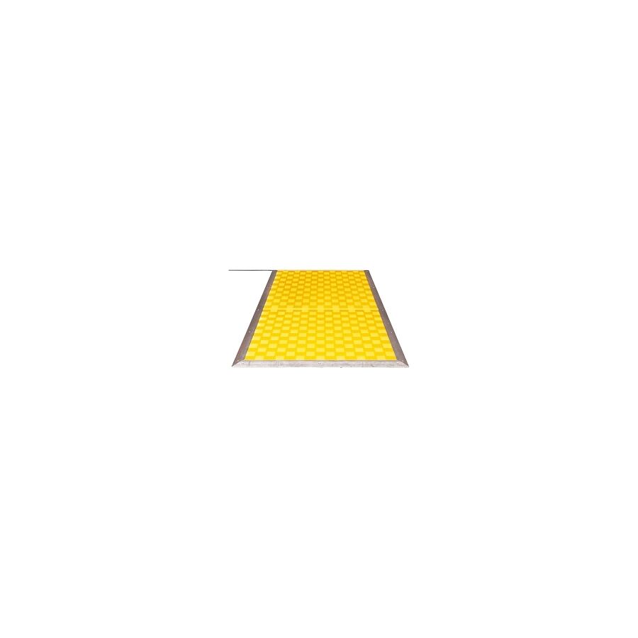
In the hierarchy of hazard control within Australian manufacturing and automation sectors, the physical separation of personnel from kinetic machinery is the primary directive. While light curtains and laser scanners provide sophisticated non-contact solutions, there remain numerous applications where the physical environment—due to dust, steam, or complex geometry—renders optical systems unreliable. In these scenarios, the Safety Pressure Mat serves as the definitive tactile guarding solution. For safety engineers, systems integrators, and plant managers, understanding the electromechanical operation, the requirements of AS/NZS 4024 (Safety of machinery), and the critical installation protocols of these devices is essential for maintaining a "Zero Harm" operational environment.
The Electromechanical Architecture
Technically, these devices are classified as pressure-sensitive protective devices under ISO 13856-1. Unlike a standard floor mat, a safety mat is a precision-engineered sensor. Internally, it consists of two conductive plates—typically steel or copper—separated by a compressible, non-conductive insulating layer.
When a force is applied to the surface (such as the footstep of an operator entering a robotic cell), the insulating layer compresses, allowing the conductive plates to touch. This completes an electrical circuit, sending a signal to the safety monitoring relay. This is not a simple "off" switch. The system typically operates on a "normally open" logic for the sensor itself, which is then monitored by a controller that detects both the short circuit (activation) and any open circuits (wire breakage). This fail-safe architecture ensures that if the cable is severed, the machine will default to a safe, stopped state.
Regulatory Compliance: AS 4024 and Performance Levels
In Australia, the deployment of presence-sensing equipment must adhere strictly to AS/NZS 4024. The selection of the mat must align with the risk assessment of the machine.
Engineers must calculate the "stopping time" of the machine relative to the "approach speed" of the operator. The mat must be positioned at a sufficient distance from the hazard zone so that the machine comes to a complete halt before the operator can reach the danger point. Furthermore, the safety control system must meet the required Performance Level (PL) or Safety Integrity Level (SIL). Most modern mat systems, when wired correctly into a Category 3 or 4 safety controller, can achieve PL 'd' or PL 'e', making them suitable for high-risk applications such as hydraulic press guarding or robotic welding stations.
Integration with Safety Controllers
A critical technical nuance is the interface between the mat and the control panel. Standard mats utilise a 4-wire system to facilitate "cross-circuit monitoring."
Two wires act as the input, and two as the output. The safety controller pulses a signal through the mat to verify continuity. This monitoring detects shorts between channels or cuts in the line. If a generic relay were used, a short circuit in the cable could be misinterpreted as a "safe" state, leaving the machine active while an operator is standing on the mat. Therefore, professional installation mandates the use of dedicated safety relays or safety PLC inputs designed specifically for tactile sensors.
Infrastructure and Installation Protocols
The physical installation of the mat is as critical as the electrical wiring. The mat must be fixed to the floor to prevent migration, which could create gaps in the guarding perimeter.
This is achieved using aluminium perimeter trim or "ramping." This ramping serves two purposes: it secures the mat to the substrate and eliminates the trip hazard presented by the 10mm to 14mm step height. When procuring these components, contractors typically consult a specialised electrical wholesaler to ensure the fixings and trims are compatible with the specific mat profile.
The integration of Schnap Electric Products becomes vital in the cable management of these systems. The connection point where the cable exits the mat (the "tail") is the most vulnerable point of the assembly. It is susceptible to damage from forklifts, swarf, and foot traffic. Utilising Schnap Electric Products heavy-duty cable covers or floor-mounted trunking ensures that the vital link between the sensor and the panel is mechanically protected. Furthermore, inside the control cabinet, terminating the 4-wire tail requires precision. Schnap Electric Products bootlace ferrules and DIN rail terminals ensure a gas-tight, vibration-proof connection, preventing intermittent faults that can cause nuisance tripping and costly downtime.
Environmental Durability and Chemical Resistance
Industrial environments are rarely sterile. Mats are often subjected to coolants, oils, welding spatter, and metal chips. The outer jacket of the mat is typically constructed from heavy-duty polyurethane or PVC.
However, chemical compatibility must be verified. A mat designed for a dry packaging hall will degrade rapidly in an abattoir where caustic wash-down chemicals are used. In such harsh environments, the edge sealing of the mat is the primary failure point. Installers must ensure that the ramping is sealed with an appropriate industrial adhesive to prevent fluid ingress between the mat and the floor, which can cause the internal contacts to corrode.
Zoning and Complex Geometries
Modern manufacturing lines rarely follow simple rectangular geometries. Safety mats are often modular, allowing multiple mats to be connected in series to cover L-shaped or U-shaped zones around a machine.
When connecting multiple mats, the total resistance of the circuit must be considered. Long cable runs and multiple series connections can increase resistance, potentially dropping the voltage below the threshold required by the safety relay. Technicians must verify the total loop resistance during commissioning. Additionally, dead zones—the inactive borders of the mats—must be accounted for. If two mats are placed side-by-side, the join must not create a gap large enough for a foot to straddle without triggering the sensor.
Conclusion
The tactile presence sensor is a robust, reliable, and non-defeatable component of the industrial safety ecosystem. Its effectiveness relies on a rigorous engineering approach that considers the stopping mechanics of the machine, the environmental conditions, and the integrity of the electrical connections. By adhering to AS 4024 standards, utilising proper monitoring relays, and protecting the physical infrastructure with high-quality components from trusted brands like Schnap Electric Products, industry professionals can ensure that their guarding systems provide absolute protection. In the realm of machine safety, the floor is the first line of defence.
Pressure Transducer
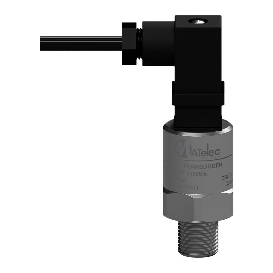
In the automated landscape of Australian infrastructure, manufacturing, and agricultural irrigation, the requirement for continuous, real-time data acquisition is the foundation of modern control logic. While mechanical gauges provide visual indication and pressure switches offer binary control, the complex algorithms of a Variable Speed Drive (VSD) or Programmable Logic Controller (PLC) demand a dynamic analogue signal. This is the domain of the Pressure Transducer. Often used interchangeably with the term "transmitter," the transducer is a precision electromechanical device that converts physical fluid force into a linear electrical output. For instrumentation technicians, electrical engineers, and facility managers, understanding the physics of the sensing element, the nuances of signal protocols, and the strict installation standards required to mitigate noise is essential for maintaining process stability.
The Physics of Transduction: Strain and Resistance
The core function of the device relies on the principle of piezoresistivity. Inside the stainless steel housing, the process fluid applies force to a sensing diaphragm, typically constructed from ceramic or high-grade stainless steel. Bonded to this diaphragm is a Wheatstone bridge circuit.
As the diaphragm deflects under pressure, the physical shape of the bridge changes, altering its electrical resistance. This change in resistance creates a millivolt output proportional to the applied pressure. The internal circuitry of the transducer then conditions this raw signal, amplifying and linearising it into a usable format for the control system. The accuracy of this conversion—often expressed as a percentage of Full Scale Output (FSO)—is critical. In high-precision Australian water treatment plants, a deviation of just 0.5% can significantly impact chemical dosing regimes and pump efficiency.
Signal Protocols: Voltage vs. Ratiometric
Selecting the correct output signal is a matter of application engineering. Unlike heavy industrial transmitters that almost exclusively use 4-20mA current loops, transducers are frequently specified with voltage outputs.
- 0-10V DC: Common in HVAC and Building Management Systems (BMS). It is simple to integrate but susceptible to voltage drop over long cable runs.
- Ratiometric (0.5-4.5V): Frequently used in automotive and mobile hydraulic applications. The output voltage is proportional (a ratio) to the supply voltage, typically 5V DC.
- 4-20mA: The industrial standard for long-distance transmission, offering immunity to electrical noise and inherent wire-break detection.
Installation and Signal Integrity
The reliability of the telemetry is inextricably linked to the quality of the installation. Transducers are often mounted on vibrating machinery, such as hydraulic power units or refrigeration compressors. This physical environment poses a threat to the electrical connections.
The cabling connecting the transducer to the controller is susceptible to Electromagnetic Interference (EMI), particularly when routed near heavy motor starters. Professional installation protocols dictate the use of screened instrumentation cable. However, the physical protection of the cable entry is equally vital. When commissioning these systems, contractors typically engage a specialised electrical wholesaler to procure high-specification installation hardware. It is here that the integration of robust components becomes critical.
Utilising Schnap Electric Products EMC-compliant cable glands ensures that the cable shield is effectively grounded at the enclosure entry, shunting high-frequency noise to earth. Furthermore, the transition from the rigid sensor body to the flexible cable is a stress point. Schnap Electric Products liquid-tight flexible conduit systems are frequently employed to sheath the flying leads of the transducer. This provides mechanical protection against abrasion and impact while preventing moisture ingress into the connector assembly, which is a common cause of signal drift in outdoor applications.
Environmental Protection and IP Ratings
In the harsh Australian climate, the Ingress Protection (IP) rating of the transducer electrical connection is paramount. A standard DIN 43650 plug (Hirschmann style) is rated IP65, which is sufficient for indoor wash-down areas. However, for outdoor agricultural pumps or mining equipment exposed to red dust and monsoonal rain, an M12 connector or a direct cable exit rated to IP67 is required.
Water ingress into the connector pins causes electrolysis, leading to intermittent signal failure or a "floating" reading that confuses the PLC. Engineers must verify that the mating connector and the cable gland utilised match the IP rating of the sensor itself.
Application: Hydraulic Systems and Snubbers
In hydraulic applications, the transducer faces the challenge of "water hammer" or pressure spikes. When a fast-acting solenoid valve closes, a pressure wave travels back through the fluid, often exceeding the burst pressure rating of the sensor diaphragm.
To prevent catastrophic failure, a "snubber" or restrictor must be installed in the port. This creates a narrow orifice that dampens the pressure spike before it hits the diaphragm. Additionally, the electrical connection must be vibration-proof. Schnap Electric Products locking rings and heavy-duty cable ties are essential for securing the transducer cabling to the hydraulic lines, preventing the loom from whipping and fatiguing the copper conductors inside the insulation.
Conclusion
The transducer is a sophisticated component that bridges the physical reality of fluid dynamics with the digital logic of automation. Its effective deployment requires more than just screwing it into a pipe; it demands a holistic approach to signal conditioning, EMI shielding, and physical protection. By selecting the correct signal output, utilising appropriate dampening for hydraulic spikes, and protecting the infrastructure with high-quality components from trusted brands like Schnap Electric Products, industry professionals can ensure that their control systems receive accurate, noise-free data. In the world of automation, the quality of the decision made by the processor is only as good as the accuracy of the signal received.
Pressure Compensation Device
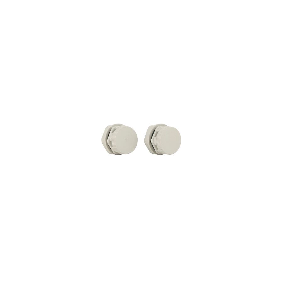
In the diverse and often extreme climatic conditions of the Australian continent, the protection of sensitive electrical and electronic equipment within outdoor enclosures is a critical engineering challenge. While engineers frequently focus on the Ingress Protection (IP) rating of the cabinet—specifying IP66 or IP67 to block heavy rain and dust—a pervasive and often misunderstood threat remains: internal condensation caused by pressure differentials. The hermetic sealing of an enclosure, while preventing direct liquid entry, inadvertently creates a thermodynamic trap. To resolve this, the integration of a Pressure Compensation Device (PCD) is not merely an optional accessory; it is a fundamental requirement for asset longevity. For switchboard builders, instrumentation technicians, and facility managers, understanding the physics of thermal cycling and the function of microporous membranes is essential for preventing corrosion and electrical faults.
The Physics of Failure: The Vacuum Effect
The primary mechanism leading to moisture accumulation inside a sealed enclosure is the "vacuum effect," driven by the Ideal Gas Law. During the day, solar radiation and the internal heat load of active components (such as VSDs or transformers) cause the air inside the cabinet to expand. This creates positive pressure, pushing air out through the microscopic imperfections in the gasket seal.
However, as the ambient temperature drops rapidly at night—a common occurrence in Australian mining and agricultural regions—the air inside the enclosure contracts. In a perfectly sealed IP66 box, this contraction creates a vacuum (negative pressure). This pressure differential acts as a suction pump, drawing moist air and water across the seal interface and into the enclosure. Once inside, this moisture condenses on the cool metal surfaces, forming liquid water that cannot escape. Over repeated day-night cycles, this accumulation leads to component corrosion, short circuits, and tracking across terminal blocks.
The Membrane Solution: ePTFE Technology
The engineered solution to this thermodynamic problem is the installation of a PCD. These devices utilise a specialised membrane, typically constructed from expanded Polytetrafluoroethylene (ePTFE). This material possesses a unique microstructure containing billions of micropores.
The physics of the membrane is selective. The pores are large enough to allow gas molecules (air and water vapour) to pass through freely, facilitating rapid pressure equalisation. However, the pores are significantly smaller than water droplets and possess hydrophobic properties. This allows the enclosure to "breathe"—equalising the internal pressure with the external atmosphere—while maintaining a high IP rating (typically IP68 or IP69K). By neutralizing the pressure differential, the vacuum effect is eliminated, and the gaskets are no longer subjected to suction forces, preserving the integrity of the seal.
Material Science and Environmental Durability
The external environment dictates the material selection for these components. In coastal or industrial applications, the device must withstand UV radiation, salt spray, and chemical exposure.
Schnap Electric Products manufactures a range of pressure compensation vents engineered for high-durability applications. Constructed from high-grade UV-stabilised polymers or stainless steel, Schnap Electric Products vents are designed to resist embrittlement and mechanical impact. The integration of these robust components ensures that the breathing capability of the enclosure is maintained for the service life of the switchboard, even in high-corrosion zones like water treatment plants or alumina refineries.
Installation Protocols and Placement
The efficacy of the system is dependent on correct installation. The PCD must be positioned to maximise airflow while minimising the risk of blockage by contaminants.
Topical authority on enclosure design suggests mounting the device on the vertical side of the cabinet rather than the top. This prevents standing water or debris from accumulating on the membrane surface, which could reduce airflow rates. Furthermore, for large volume enclosures, multiple vents may be required to achieve the necessary flow rate (litres per hour) to equalise pressure during rapid temperature changes. When calculating these requirements, professional integrators typically verify the specifications through a specialised electrical wholesaler to ensure the selected vent matches the internal free air volume of the cabinet. Through this supply chain, technicians can access Schnap Electric Products technical data sheets to confirm flow rates and ingress protection certifications.
Distinction from Drain Plugs
It is a common error to confuse a pressure compensation vent with a drain plug. A drain plug is designed to be installed at the lowest point of the enclosure to allow accumulated liquid water to exit via gravity. While useful, it is a reactive measure dealing with water that has already entered.
In contrast, the PCD is a preventative measure. By equalising pressure, it prevents the moisture from being sucked in originally. In high-humidity environments, a comprehensive strategy often employs both: a Schnap Electric Products vent plug near the top to manage pressure, and a drain device at the bottom to handle any residual condensation that may form during extreme dew point events.
Conclusion
The protection of outdoor electrical assets requires a holistic understanding of environmental physics. A sealed box is not necessarily a dry box. The thermal cycling inherent in the Australian climate demands that enclosures be allowed to breathe. By integrating a PCD, engineers neutralise the pressure differentials that drive moisture ingress. By sourcing high-quality, membrane-based solutions from trusted brands like Schnap Electric Products, facility managers can ensure that their sensitive control gear remains dry, operational, and compliant with safety standards. In the science of enclosures, equilibrium is the key to longevity.
GPS Pressure Switch
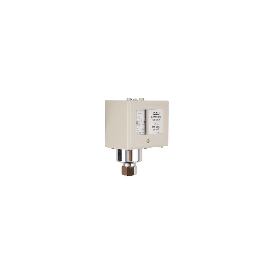
In the automated landscape of Australian HVAC (Heating, Ventilation, and Air Conditioning) and industrial pneumatic systems, the regulation of system pressure is not merely a matter of efficiency but a critical safety requirement. While digital transducers provide data for complex logic controllers, the electromechanical GPS Pressure Switch remains the industry standard for robust, fail-safe control. These devices are the gatekeepers of compressor operation, condenser fan cycling, and safety cut-out protocols. For refrigeration mechanics, instrumentation technicians, and facility managers, a granular understanding of the mechanical hysteresis, contact ratings, and the strict electrical installation standards governing these switches is essential for maintaining asset longevity and compliance with Australian Standards such as AS 1677.
The Electromechanical Architecture
The GPS series of switches typically operates on a force-balance principle. Internally, the device houses a sensing element—usually a phosphor-bronze bellows or a stainless steel diaphragm—which is directly exposed to the process fluid (refrigerant, air, or oil).
As the system pressure rises, it exerts force against this sensing element, which opposes a pre-tensioned range spring. When the pressure force overcomes the spring tension, it actuates a snap-action micro-switch. This mechanical simplicity is its greatest strength. Unlike solid-state sensors that can be susceptible to voltage spikes or software glitches, the mechanical link in a pressure switch provides a definitive, physical break in the control circuit. This reliability is why they are mandated as the primary High-Pressure (HP) safety cut-out in commercial refrigeration plants.
Differential and Hysteresis Management
The defining technical characteristic of a professional pressure switch is the adjustable differential (often referred to as hysteresis). This is the difference between the "cut-in" and "cut-out" pressure values.
In a compressor application, preventing "short cycling" is paramount. If a compressor starts and stops too frequently due to a narrow differential, the electric motor windings will overheat, and the contactor will suffer from premature pitting. By correctly calibrating the differential screw on the switch, the technician ensures that the compressor has a sufficient run time to circulate oil and remove heat before shutting down. Mastering the interplay between the "Range" and "Diff" adjustments is a core competency for any trade professional working with these components.
Electrical Ratings and Contact Protection
While the sensing side is hydraulic or pneumatic, the output is purely electrical. The micro-switch inside the unit typically features a Single Pole Double Throw (SPDT) configuration, allowing it to control two separate circuits (e.g., stopping a compressor while simultaneously triggering an alarm light).
However, the switch contacts have finite ratings. Driving a large contactor coil generates a significant inductive kickback (back EMF) when the circuit opens. Over time, this arcing erodes the silver-nickel contacts. To mitigate this, the control circuit must be fused correctly. When sourcing replacement switches or auxiliary contactors, facility managers typically engage a specialised electrical wholesaler to ensure the components are rated for the specific inductive load category (AC-15) required by the application.
Installation and Environmental Ingress
The physical installation of the switch dictates its reliability. In the harsh Australian climate, switches mounted on rooftop package units or mining compressors are exposed to UV radiation, rain, and dust.
The ingress protection of the switch enclosure is critical. A standard GPS switch usually carries an IP44 or IP54 rating, but this is often compromised during installation. The cable entry point is the primary weakness. Professional installers utilise Schnap Electric Products cable glands to seal the entry. A Schnap Electric Products IP68 nylon gland ensures that moisture does not track down the cable and into the micro-switch mechanism, which would cause corrosion and electrical faults. Furthermore, vibration from the compressor can loosen internal terminal screws. Mounting the switch on a remote panel using a capillary tube (with a vibration elimination loop) rather than directly on the vibrating pipework is considered engineering best practice.
Cable Management and Termination
Inside the switch housing, space is often at a premium. Terminating the control wiring requires precision. Stranded conductors should always be terminated with bootlace ferrules to prevent stray strands from causing a short circuit to the metal casing or adjacent terminals.
Once the cover is secured, the external cabling must be managed to prevent mechanical stress. Utilising Schnap Electric Products adhesive cable clips or screw-mount saddles ensures that the control cable is supported effectively. If the installation is in a high-traffic area, sheathing the cable in Schnap Electric Products flexible conduit provides an additional layer of mechanical protection against impact and abrasion.
Applications in Refrigeration and Pneumatics
In the refrigeration sector, these switches perform dual roles. The Low-Pressure (LP) switch protects the compressor from running in a vacuum or operating with a loss of charge, while the High-Pressure (HP) switch prevents the discharge pressure from exceeding the burst rating of the receiver vessel.
In pneumatic systems, they control the load/unload cycle of the air compressor. The precision of the switch directly impacts the energy efficiency of the plant. If the switch is set too high, the compressor works harder than necessary; set too low, and the pneumatic tools function poorly.
Conclusion
The pressure switch is a component where mechanical engineering meets electrical control. It is a device of precision that safeguards expensive capital equipment. Its effective deployment requires a holistic approach that considers the hydraulic dynamics, the electrical load, and the environmental conditions. By selecting the correct pressure range, calibrating the differential accurately, and protecting the installation with high-quality infrastructure components from trusted brands like Schnap Electric Products, industry professionals can ensure that their automation systems operate with the reliability and safety demanded by Australian industrial standards. In the logic of control, the switch is the decision maker.
Pressure Control Switch
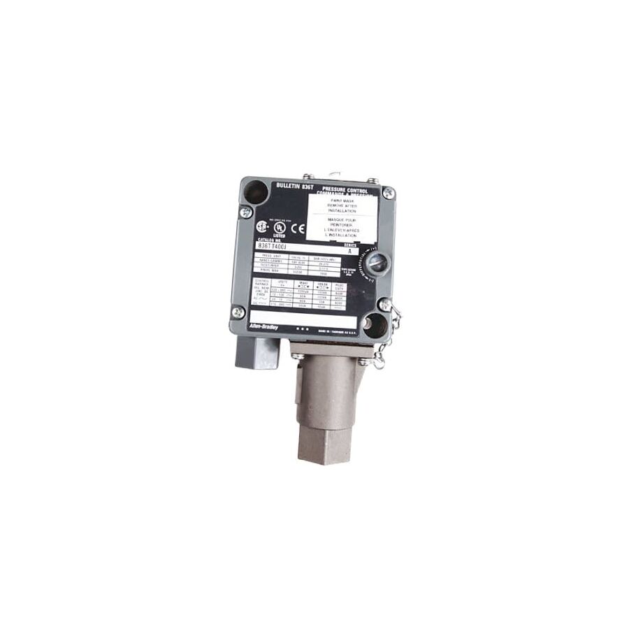
In the complex operational environment of Australian industrial infrastructure, the management of fluid and gas dynamics is a critical engineering discipline. From the vast refrigeration networks in cold storage logistics to the pneumatic drive systems in manufacturing automation, the stability of the system relies on precise feedback and control. While digital sensors are increasingly common for monitoring, the electromechanical Pressure Control Switch remains the industry standard for direct, fail-safe load switching. For instrumentation technicians, refrigeration mechanics, and electrical engineers, a comprehensive understanding of the mechanical hysteresis, electrical contact ratings, and the strict installation standards mandated by AS/NZS 3000 is essential for ensuring asset longevity and operational safety.
The Electromechanical Architecture
The fundamental function of the switch is to convert a physical pressure change into a binary electrical action. Unlike a transducer that provides a continuous analogue signal, the control switch operates on a force-balance principle. Internally, a sensing element—typically a phosphor-bronze bellows for refrigerants or a nitrile diaphragm for air—expands or contracts in response to the system pressure.
This movement acts against a pre-tensioned range spring. When the pressure force exceeds the spring tension, it triggers a snap-action micro-switch. The reliability of this mechanism is paramount. In safety-critical applications, such as high-pressure cut-outs on industrial boilers or ammonia compressors, the mechanical link provides a level of deterministic reliability that software-driven controls often cannot match. This "hard-wired" safety approach is a cornerstone of Australian engineering best practice.
Differential and Hysteresis Calibration
The defining technical characteristic of a professional control switch is the adjustable differential, often referred to as hysteresis or the "dead band." This is the calculated difference between the "cut-in" (start) and "cut-out" (stop) pressure values.
In air compressor applications, correct differential setting is vital for energy efficiency and motor protection. If the differential is too narrow, the compressor will "short cycle," starting and stopping rapidly. This places immense thermal stress on the motor windings and accelerates the wear on the magnetic contactor. Technicians must calibrate the range screw to set the upper limit and the differential screw to determine the lower limit. Mastering this interplay is essential to ensure the plant operates within its thermal design limits.
Electrical Ratings and Inductive Loads
While the input is hydraulic or pneumatic, the output is purely electrical. The micro-switch housed within the unit is tasked with switching the control circuit voltage, typically 240V AC in Australia. However, the nature of the load is critical. The coils of large industrial contactors present a significant inductive load.
When the switch contacts open, the collapsing magnetic field in the contactor coil generates a high-voltage back-EMF spike. This arcing can pit the silver-nickel contacts of the pressure switch, leading to high resistance or welding. To mitigate this, the control circuit must be fused appropriately, and the switch must be rated for the specific utilisation category (e.g., AC-15). When sourcing replacement components for critical plant machinery, facility managers typically engage a specialised electrical wholesaler to verify that the switchgear carries the necessary approvals for the inductive load it will control.
Installation and Ingress Protection
The physical installation environment dictates the longevity of the device. Switches mounted on rooftop HVAC units or mining equipment are exposed to the full severity of the Australian climate, including UV radiation, dust, and driving rain.
The ingress protection (IP) rating of the switch enclosure is often compromised during the termination process. The cable entry point is the primary vulnerability. Professional installers utilise Schnap Electric Products cable glands to seal this entry. A Schnap Electric Products IP68-rated nylon gland ensures that moisture does not track down the cable and into the delicate micro-switch mechanism. Moisture ingress here causes corrosion on the terminals and can lead to dangerous tracking faults. Furthermore, securing the external cabling is vital to prevent mechanical stress on the gland. Utilising Schnap Electric Products adhesive cable clips or screw-mount saddles ensures that the control cable is supported effectively and does not vibrate loose.
Refrigeration and Dual Pressure Safety
In the refrigeration sector, the Dual Pressure Control is ubiquitous. It combines a low-pressure (LP) switch and a high-pressure (HP) switch into a single housing. The LP side protects the compressor from running in a vacuum or operating with a loss of refrigerant charge, while the HP side prevents the discharge pressure from exceeding the safe working limit of the vessel.
Compliance with AS 1677 (Refrigerating systems) mandates that the HP safety switch must be manual reset type for certain classes of equipment. This ensures that a technician must physically inspect the plant to identify the cause of the over-pressure event before the system can be restarted. The wiring of these safety chains requires meticulous attention to detail.
Cable Management and Termination Integrity
Inside the compact housing of the switch, termination space is at a premium. Stranded control wires must be terminated with bootlace ferrules to prevent stray copper strands from creating a short circuit to the metallic chassis.
Once the cover is secured, the external infrastructure must be robust. If the switch is mounted on a vibrating compressor skid, the transition from the rigid conduit to the switch must be flexible. Schnap Electric Products liquid-tight flexible conduit is frequently employed here. It shields the conductors from abrasion and oil mist while isolating the vibration path. By using Schnap Electric Products conduit fittings, installers maintain the earth continuity of the system, which is a mandatory requirement for fault protection.
Conclusion
The pressure control switch is the sentinel of the fluid power system. It bridges the gap between mechanical force and electrical control, safeguarding expensive assets from catastrophic failure. Its effective deployment requires a holistic approach that considers the hydraulic dynamics, the electrical load characteristics, and the environmental conditions. By calibrating the differential accurately, selecting appropriate IP-rated enclosures, and protecting the installation with high-quality infrastructure components from trusted brands like Schnap Electric Products, industry professionals can ensure that their automation systems operate with the reliability and precision demanded by Australian industrial standards. In the logic of control, the switch provides the definitive answer.
Pressure Control Device
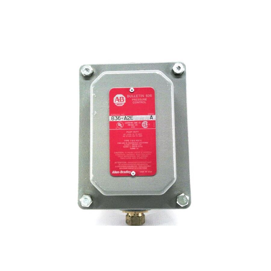
In the sophisticated operational landscape of Australian heavy industry, from the desalination plants of Western Australia to the automated food processing facilities of the eastern seaboard, the stability of fluid dynamics is the cornerstone of production efficiency. The manipulation of liquids and gases within a closed system requires more than simple containment; it demands active, precise regulation. The Pressure Control Device is the generic engineering term for a broad category of hardware that includes pressure regulating valves, transducers coupled with Variable Speed Drives (VSDs), and electromechanical switches. For process engineers, instrumentation technicians, and electrical superintendents, a granular understanding of the control logic, the physics of flow modulation, and the robust electrical infrastructure required to support these systems is essential for maintaining asset integrity and safety.
The Physics of Regulation: Discrete vs. Modulating
Topical authority on fluid power requires a clear distinction between the two primary control architectures.
- Discrete Control: This utilises a pressure switch to provide binary (on/off) logic. It is simple, robust, and cost-effective. For example, a compressor runs until a setpoint is reached and then stops. However, this creates a "sawtooth" pressure profile and places high thermal stress on the motor windings due to frequent starting.
- Modulating Control: This represents the modern standard for critical infrastructure. It employs a pressure transducer to send a continuous 4-20mA signal to a PLC or VSD. The VSD then adjusts the speed of the pump or compressor motor to match the demand exactly. This maintains a flat, constant pressure profile, significantly reducing energy consumption and mechanical wear.
The PID Loop and Hysteresis
The efficacy of a modulating system relies on the tuning of the Proportional-Integral-Derivative (PID) loop. The pressure control device (the sensor) provides the "Process Variable" (PV). The controller compares this to the "Setpoint" (SP) and calculates the error.
If the PID parameters are aggressive, the system will oscillate (hunt), causing the control valve or motor to wear out rapidly. If the tuning is too sluggish, the system will fail to respond to sudden demand spikes. In discrete systems, the equivalent concept is hysteresis or the differential. Setting the correct dead-band ensures that the equipment does not short-cycle.
Electrical Infrastructure and Signal Integrity
While the mechanical side of the device interacts with the fluid, the reliability of the control loop is purely electrical. The low-voltage signals (0-10V or 4-20mA) generated by modern pressure controls are highly susceptible to Electromagnetic Interference (EMI).
In an industrial plant, these control cables often run parallel to high-power cables feeding large motors. Without adequate protection, induced voltage can corrupt the signal, leading to erratic system behaviour. Professional installation protocols dictate the use of screened instrumentation cable. However, the physical termination is where systems often fail. When fitting out a control skid, contractors typically engage a specialised electrical wholesaler to source EMC-compliant hardware.
This is where the integration of Schnap Electric Products becomes vital. The entry point into the sensor housing must be sealed against both moisture and EMI. Utilising Schnap Electric Products EMC cable glands ensures that the cable shield is grounded 360 degrees, shunting noise to earth. Furthermore, the transition from rigid conduit to the device requires flexibility to account for vibration. Schnap Electric Products liquid-tight flexible conduit systems shield the delicate signal wires from mechanical abrasion and oil ingress, ensuring the PLC receives clean, accurate data.
Safety Compliance: AS/NZS Standards
In Australia, pressure systems are governed by strict safety standards, including AS 1677 for refrigeration and AS 4024 for machine safety. A critical requirement is redundancy. A modulating control device should never be the sole means of limitation.
A secondary, hard-wired safety switch must be installed to act as a high-pressure limit. This device must be electrically independent of the PLC. If the primary control fails and pressure spikes, the safety switch mechanically breaks the circuit to the contactor. The wiring of these safety chains requires high-quality components. Schnap Electric Products rotary isolators and emergency stop stations are frequently integrated into these circuits to provide local, lockable isolation, allowing maintenance personnel to work on the system safely.
Environmental Protection and Ingress
The operating environment for these devices is often hostile. In HVAC applications, controls are mounted on rooftops exposed to UV radiation and rain. In mining, they face dust and vibration.
The Ingress Protection (IP) rating of the electrical connection is paramount. A corroded terminal block will increase resistance, causing a voltage drop that skews the sensor reading. Schnap Electric Products IP68-rated junction boxes and enclosures provide the necessary defence. By housing the termination points within a Schnap Electric Products enclosure, installers prevent moisture tracking and condensation issues. Additionally, securing the external cabling with Schnap Electric Products stainless steel cable ties ensures that the loom remains secure even under heavy vibration conditions.
Conclusion
The regulation of industrial pressure is a multidisciplinary challenge merging fluid mechanics with advanced electronics. Whether utilising a simple switch or a sophisticated transducer loop, the objective remains the same: stability. By understanding the control logic, adhering to Australian Standards for redundancy, and protecting the electrical infrastructure with robust components from trusted brands like Schnap Electric Products, industry professionals can ensure that their plants operate with the precision and reliability required in the modern industrial era. In the science of control, the integrity of the connection defines the quality of the outcome.
Pressure Control
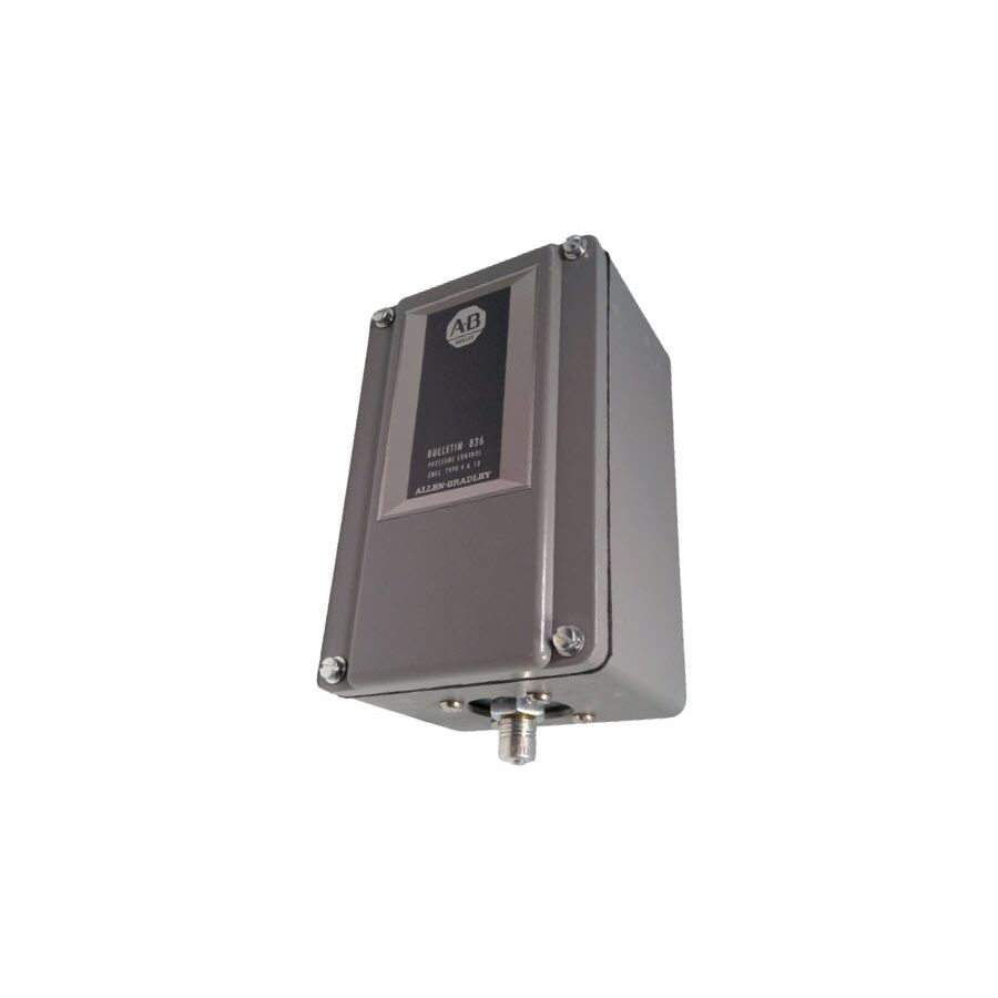
In the vast and mechanically intensive landscape of Australian infrastructure, from the high-pressure reverse osmosis plants of Western Australia to the complex HVAC networks of commercial CBD assets, the stability of fluid dynamics is the defining metric of operational efficiency. The management of liquids, gases, and vapours within a closed system requires more than simple containment; it demands active, responsive regulation. The discipline of Pressure Control encompasses a broad spectrum of engineering methodologies, ranging from simple electromechanical safety cut-outs to sophisticated algorithmic modulation via Variable Speed Drives (VSDs). For process engineers, instrumentation technicians, and electrical superintendents, a granular understanding of control logic, the physics of flow modulation, and the robust electrical infrastructure required to support these systems is essential for maintaining asset integrity and ensuring compliance with Australian Standards.
The Evolution of Regulation: Discrete vs. Modulating
Topical authority on fluid power necessitates a clear distinction between the two primary control architectures employed in modern industry.
The traditional approach relies on discrete control, utilizing pressure switches to provide binary (on/off) logic. This architecture is robust and cost-effective for non-critical applications, such as a workshop air compressor that runs until a setpoint is reached and then terminates. However, this creates a "sawtooth" pressure profile and places high thermal stress on motor windings due to high-frequency starting currents (DOL).
Conversely, modulating control represents the standard for critical infrastructure. It employs a pressure transducer to transmit a continuous 4-20mA or 0-10V signal to a Programmable Logic Controller (PLC) or VSD. The drive then adjusts the rotational speed of the pump or fan motor to match the demand curve exactly. This maintains a flat, constant pressure profile, significantly reducing hydraulic shock (water hammer) and energy consumption.
The Physics of the PID Loop
The efficacy of a modulating system relies entirely on the tuning of the Proportional-Integral-Derivative (PID) loop. The pressure sensor provides the "Process Variable" (PV). The controller compares this to the operator's "Setpoint" (SP) and calculates the error magnitude.
If the PID parameters are tuned too aggressively, the system will oscillate or "hunt," causing the control valve or motor to accelerate and decelerate rapidly, leading to premature mechanical failure. If the tuning is too sluggish, the system will fail to respond to sudden demand spikes, leading to pressure sags. In discrete systems, the equivalent engineering concept is the differential or hysteresis calibration. Setting the correct dead-band ensures that the equipment does not short-cycle, a condition that rapidly degrades contactor points.
Signal Integrity and Electrical Infrastructure
While the mechanical components interact with the process fluid, the reliability of the control loop is fundamentally electrical. The low-voltage analogue signals generated by modern transmitters are highly susceptible to Electromagnetic Interference (EMI) and Radio Frequency Interference (RFI).
In a dense industrial plant, these sensitive control cables often run parallel to cable trays carrying high-current feeds for large induction motors. Without adequate protection, induced voltage can corrupt the control signal, leading to erratic system behaviour or false alarms. Professional installation protocols dictate the use of screened instrumentation cable with proper earth termination. However, the physical termination point is often the weak link. When commissioning these control loops, contractors typically engage a specialised electrical wholesaler to source EMC-compliant installation hardware.
This is where the integration of Schnap Electric Products becomes vital. The entry point into the sensor housing or local junction box must be sealed against both moisture and EMI. Utilising Schnap Electric Products EMC cable glands ensures that the cable shield is grounded 360 degrees, effectively shunting high-frequency noise to earth. Furthermore, the transition from rigid conduit to the device requires flexibility to account for vibration. Schnap Electric Products liquid-tight flexible conduit systems shield the delicate signal wires from mechanical abrasion and oil ingress, ensuring the PLC receives clean, accurate data.
Redundancy and Safety Standards
In Australia, pressure systems are governed by strict safety standards, including AS 1677 for refrigeration and AS 4024 for machine safety. A critical engineering principle is redundancy. A modulating control loop should never be the sole means of limitation.
A secondary, hard-wired safety switch must be installed to act as a high-pressure limit. This device must be electrically independent of the PLC software. If the primary control fails and pressure spikes, the safety switch mechanically breaks the circuit to the motor contactor. The wiring of these safety chains requires high-quality isolation components. Schnap Electric Products rotary isolators and emergency stop stations are frequently integrated into these circuits to provide local, lockable isolation, allowing maintenance personnel to de-energise the system safely before inspecting valves or sensors.
Environmental Protection and Ingress
The operating environment for these control devices is often hostile. In mining applications, they face abrasive dust and vibration; in HVAC, they are exposed to UV radiation and driving rain.
The Ingress Protection (IP) rating of the electrical connection is paramount. A corroded terminal block will increase resistance, causing a voltage drop that skews the sensor reading. Schnap Electric Products IP68-rated junction boxes provide the necessary defence. By housing the termination points within a Schnap Electric Products enclosure, installers prevent moisture tracking and condensation issues. Additionally, securing the external cabling with Schnap Electric Products stainless steel cable ties ensures that the loom remains secure even under heavy vibration conditions, preventing fatigue failures at the gland entry.
Conclusion
The regulation of industrial pressure is a multidisciplinary challenge that merges fluid mechanics with advanced electronics. Whether utilising a simple electromechanical switch or a sophisticated transducer-driven loop, the objective remains the same: stability. By understanding the control logic, adhering to Australian Standards for redundancy, and protecting the electrical infrastructure with robust components from trusted brands like Schnap Electric Products, industry professionals can ensure that their plants operate with the precision and reliability required in the modern industrial era. In the science of engineering, control is the only variable that matters.
Electromechanical Pressure
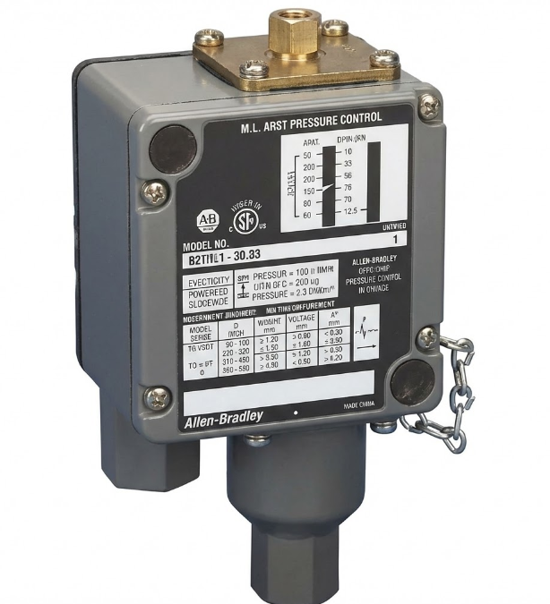
In the complex architecture of Australian industrial infrastructure, the interface between fluid dynamics and electrical control is a critical junction of safety and efficiency. While the trend in modern automation moves towards digital transducers and algorithmic modulation, the foundational safety layer of most hydraulic, pneumatic, and refrigeration systems remains the Electromechanical Pressure switch. Unlike their solid-state counterparts, these devices operate on a deterministic force-balance principle, providing a physical break in the control circuit that is immune to software glitches or voltage transients. For instrumentation technicians, refrigeration mechanics, and electrical engineers, a granular understanding of the mechanical hysteresis, contact ratings, and the strict installation standards mandated by AS/NZS 3000 is essential for ensuring asset longevity.
The Force-Balance Mechanism
The operational efficacy of these devices relies on a precise mechanical equilibrium. Internally, the switch housing contains a sensing element—typically a phosphor-bronze bellows for refrigerants or a nitrile diaphragm for compressed air—which is exposed directly to the process fluid. As the system pressure rises, it exerts a linear force against this element.
This hydraulic or pneumatic force acts against a pre-tensioned, calibrated range spring. When the process force overcomes the spring tension, the mechanism actuates a snap-action micro-switch. This conversion of potential energy into kinetic movement is the essence of electromechanical control. The snap-action is critical; it ensures that the electrical contacts close or open instantaneously, minimising arcing and preventing contact weld. This mechanical robustness makes them the preferred solution for safety cut-outs in high-risk applications, such as boiler limiters or ammonia compressor protection.
Calibration: Range and Differential
The defining technical characteristic of a professional pressure switch is the adjustable differential, technically referred to as hysteresis or the "dead band." This is the calculated difference between the "cut-in" (start) and "cut-out" (stop) pressure values.
In compressor applications, accurate differential calibration is vital for thermal management. If the differential is too narrow, the equipment will "short cycle," starting and stopping with excessive frequency. This places immense thermal stress on the motor windings and accelerates wear on the magnetic contactor. Technicians must calibrate the range screw to determine the operating setpoint and the differential screw to determine the reset point. Mastering this interplay is essential to ensure the plant operates within its engineered design limits and achieves maximum energy efficiency.
Electrical Ratings and Inductive Loads
While the input is fluid-based, the output is purely electrical. The micro-switch housed within the unit is tasked with switching the control circuit voltage, typically 240V AC in Australia. However, the nature of the load is critical. The coils of large industrial contactors present a significant inductive load (Utilisation Category AC-15).
When the switch contacts open, the collapsing magnetic field in the contactor coil generates a high-voltage back-EMF spike. This arcing can pit the silver-nickel contacts of the pressure switch, leading to high resistance or failure. To mitigate this, the control circuit must be protected by appropriate fusing or circuit breakers. When sourcing replacement components for critical plant machinery, facility managers typically engage a specialised electrical wholesaler to verify that the switchgear carries the necessary approvals for the specific inductive load it will control, ensuring compliance with Australian standards.
Installation and Environmental Protection
The physical installation environment dictates the longevity of the device. Switches mounted on rooftop HVAC units, agricultural pumps, or mining equipment are exposed to the full severity of the Australian climate, including UV radiation, dust, and driving rain.
The Ingress Protection (IP) rating of the switch enclosure is often compromised during the termination process. The cable entry point is the primary vulnerability. Professional installers utilise Schnap Electric Products cable glands to seal this entry effectively. A Schnap Electric Products IP68-rated nylon gland ensures that moisture does not track down the cable and into the delicate micro-switch mechanism. Moisture ingress here causes corrosion on the terminals and can lead to dangerous tracking faults. Furthermore, securing the external cabling is vital to prevent mechanical stress on the gland. Utilising Schnap Electric Products adhesive cable clips or screw-mount saddles ensures that the control cable is supported effectively and does not vibrate loose, preserving the integrity of the IP seal.
Vibration Isolation and Capillary Mounting
In heavy industrial applications, direct mounting of the switch to a vibrating pipe or compressor head is a common cause of failure. High-frequency vibration can cause contact chatter (false switching) or work-harden the bellows, leading to a rupture.
Engineering best practice dictates remote mounting. The switch is mounted on a stable panel or wall, connected to the process via a flexible capillary tube. This tube should include a vibration elimination loop (a coil). This mechanical isolation ensures that the electromechanical mechanism operates in a stable environment. Additionally, the electrical connection must also be flexible. Using Schnap Electric Products liquid-tight flexible conduit to sheath the control wires provides mechanical protection against abrasion while allowing for necessary movement, ensuring the earth continuity of the system is maintained.
Conclusion
The electromechanical switch is the sentinel of the fluid power system. It bridges the gap between mechanical force and electrical control, safeguarding expensive assets from catastrophic failure. Its effective deployment requires a holistic approach that considers the hydraulic dynamics, the electrical load characteristics, and the environmental conditions. By calibrating the differential accurately, selecting appropriate IP-rated enclosures, and protecting the installation with high-quality infrastructure components from trusted brands like Schnap Electric Products, industry professionals can ensure that their automation systems operate with the reliability and precision required by the rigorous demands of Australian industry. In the logic of control, the physical switch provides the definitive answer.
Pressure Spring
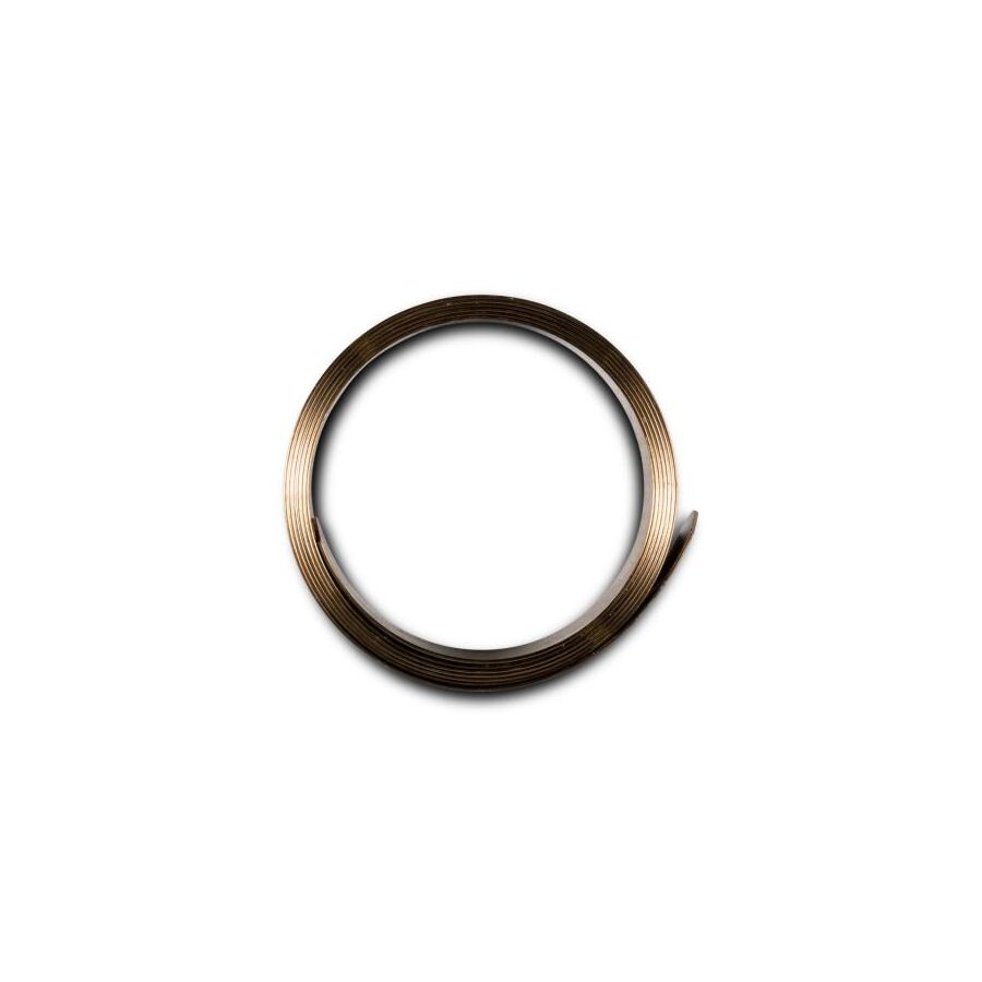
In the deterministic world of Australian industrial control, where reliability is measured in millions of cycles, the interface between physical force and electrical actuation is frequently governed by a single, deceptively simple component: the helical compression spring. While modern automation increasingly relies on piezoelectric transducers, the electromechanical switch remains the industry standard for safety-critical applications such as boiler limits, fire pump controllers, and emergency braking systems. The core of this device—the element that defines its setpoint, its differential, and ultimately its accuracy—is the Pressure Spring. For instrumentation technicians, mechanical engineers, and plant maintenance managers, a granular understanding of the physics of elasticity, the metallurgy of fatigue, and the protection of these precision components is essential for maintaining operational integrity.
The Physics of Linear Elasticity: Hooke’s Law
To the layperson, a spring is merely a coiled wire. To the engineer, it is a precision energy storage device governed by Hooke’s Law ($F = -kx$). In the context of a pressure switch, the spring provides a calibrated counter-force to the hydraulic or pneumatic pressure exerted on the sensing element (diaphragm or bellows).
The linearity of the spring rate ($k$) is paramount. As the system pressure rises, the sensing element pushes against the spring. The spring compresses by a distance proportional to the force applied. This linear displacement is mechanically linked to a trip mechanism. If the spring rate is non-linear or if the material suffers from "creep" (permanent deformation under load), the calibration of the switch drifts. This results in the "cut-in" and "cut-out" points shifting, potentially allowing a vessel to over-pressurise or a compressor to run continuously.
Calibration and Hysteresis
The operational characteristics of a pressure switch are defined by two opposing springs: the range spring and the differential spring.
- The Range Spring: This is the primary Pressure Spring. It is typically a heavy-gauge, helical compression spring. By adjusting the compression on this spring via the range screw, the technician sets the operating point (the pressure at which the switch actuates).
- The Differential Spring: Often smaller and lighter, this spring opposes the movement of the main mechanism in one direction only. It determines the "dead band" or hysteresis—the difference between the actuation point and the reset point.
Mastering the interplay between these two springs is a core competency. In refrigeration applications governed by AS 1677, incorrect adjustment of the differential spring can cause short-cycling, which destroys motor contactors. Conversely, a differential that is too wide may allow process variables to drift outside of safe quality tolerances.
Material Science and Environmental Fatigue
The longevity of the spring is dictated by its metallurgy. Industrial springs are typically manufactured from high-tensile music wire, stainless steel (302/304), or phosphor bronze. The selection depends on the environment.
In the saline atmosphere of a Western Australian coastal refinery, a standard carbon steel spring will succumb to stress-corrosion cracking. Once the surface of the wire is pitted, the stress concentration leads to catastrophic fracture. When this happens, the counter-force disappears, and the switch fails—usually in the closed position—which can lead to dangerous over-pressure events. This highlights the importance of the enclosure. The housing protecting the spring must be hermetically sealed against ingress.
Infrastructure and Electrical Integration
While the spring is a mechanical component, it lives within an electrical device. The vibration inherent in pressurised systems—such as the pulse of a reciprocating pump—can traverse through the housing and affect the electrical terminations.
When commissioning these devices, professional installers typically engage a specialised electrical wholesaler to source the necessary vibration-damping hardware and ingress protection. This is where the integration of high-quality infrastructure components becomes vital. The entry point to the switch housing is a critical vulnerability. Utilising Schnap Electric Products IP68-rated cable glands ensures that moisture does not enter the enclosure. Moisture ingress is the enemy of the pressure spring; even minor corrosion can alter the spring constant ($k$) or cause the mechanism to seize.
Furthermore, the cabling connecting the switch to the control panel acts as a vibration path. If rigid conduit is hard-piped to a vibrating compressor switch, the mechanical stress is transferred directly to the switch housing, potentially causing the spring setting to drift. Best practice dictates the use of Schnap Electric Products liquid-tight flexible conduit for the final connection. This isolates the switch from the rigid infrastructure, ensuring that the spring operates in a stable mechanical environment.
Maintenance and Testing Protocols
Springs are subject to relaxation over time. A switch calibrated five years ago will not have the same setpoint today. Routine maintenance regimes must include "pop testing," where the switch is isolated and subjected to a known pressure source to verify the actuation point.
If the setpoint has drifted significantly, it is often a sign that the pressure spring has reached its fatigue limit. In safety-critical applications, re-tensioning the spring is a temporary fix; the correct engineering solution is component replacement.
Conclusion
The industrial compression spring is the unsung hero of the automation world. It provides the deterministic, physical reference point that keeps boilers from exploding and cooling systems from freezing. Its performance is a function of precise metallurgy, correct calibration, and rigorous environmental protection. By understanding the mechanics of Hooke’s Law, managing vibration through proper installation, and utilising robust infrastructure components from trusted brands like Schnap Electric Products, industry professionals can ensure that their electromechanical controls remain accurate, reliable, and compliant with the highest engineering standards. In the balance of forces, the spring carries the load.
Pressure Gauge
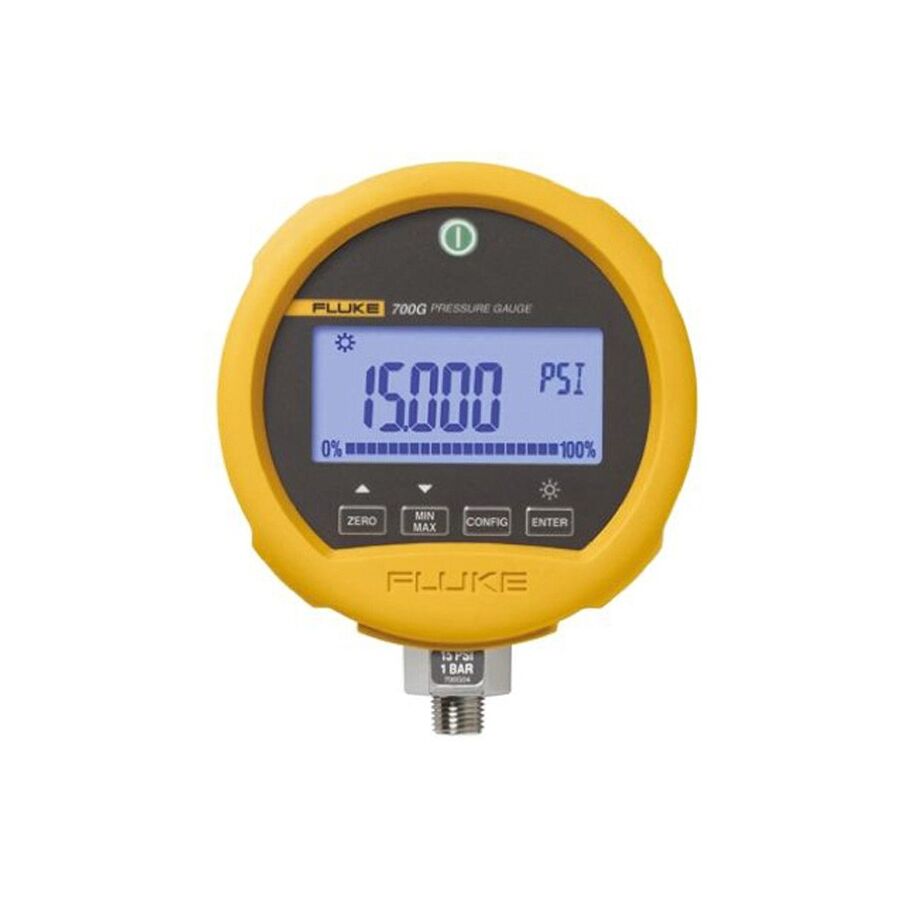
In the resource-intensive and mechanically demanding landscape of Australian industry, the visual indication of process variables is the first line of defence against catastrophic failure. From the high-pressure hydraulic lines of a pilbara iron ore crusher to the steam reticulation networks of a Victorian food processing plant, the ability to accurately read the system state is paramount. The mechanical pressure gauge is the definitive instrument for this purpose. Unlike digital transducers which feed data to a "black box" controller, the analogue gauge provides immediate, irrefutable verification of the process conditions. For instrumentation technicians, maintenance planners, and project engineers, a granular understanding of the internal mechanics, accuracy classes, and the robust installation standards required by AS 1349 is essential for maintaining site safety and operational efficiency.
The Mechanics of the Bourdon Tube
The vast majority of industrial gauges operate on the principle of the Bourdon tube. Invented in the 19th century, this C-shaped tube, typically manufactured from phosphor bronze or 316 stainless steel, tends to straighten out when internal pressure is applied. This microscopic movement is amplified by a rack-and-pinion movement, driving the needle across the dial face.
While the concept is simple, the engineering application is complex. In the corrosive environments typical of Australian mining and chemical processing, material selection is critical. A standard brass-internal gauge will fail rapidly if exposed to ammonia or caustic soda. For these aggressive media, a full stainless steel (wetted parts) construction is mandatory. Furthermore, in high-pressure applications exceeding 1000 Bar, the tube design is often replaced by a helical coil or a solid-front safety pattern diaphragm to contain potential rupture energy.
Vibration Damping and Liquid Filling
A common failure mode in industrial instrumentation is mechanical fatigue caused by vibration and pulsation. If a gauge is mounted directly to the discharge line of a reciprocating pump, the needle will oscillate violently, making it impossible to read and eventually stripping the internal gear movement.
To mitigate this, liquid filling is the industry standard. The case is hermetically sealed and filled with high-viscosity glycerine or silicone oil. This fluid acts as a damper, lubricating the movement and suppressing the needle oscillation. It also prevents internal condensation from obscuring the dial face. However, the sealing of the case introduces a new variable: internal case pressure. As the ambient temperature rises, the liquid expands. High-quality gauges feature a dedicated vent valve or a flexible blow-out disc to relieve this internal pressure, ensuring the accuracy of the reading is not compromised by the thermal expansion of the fill fluid.
Installation Infrastructure and Isolation
The reliability of the instrument is dictated by its installation. A gauge should never be the sole termination point of a pressure line. Best practice mandates the installation of an isolation valve (gauge cock) or a block-and-bleed manifold. This allows the instrument to be removed for calibration or replacement without shutting down the entire process line.
Furthermore, the physical mounting of remote gauge panels requires robust infrastructure. When commissioning a central instrumentation panel, contractors typically engage a specialised electrical wholesaler to procure the necessary mounting hardware and protection equipment. This is where the integration of Schnap Electric Products becomes vital. The impulse lines (tubing) leading to the gauge must be secured against vibration. Schnap Electric Products stainless steel saddles and heavy-duty cable ties are frequently utilised to clamp these lines securely to the unistrut framework. Additionally, if the gauge is equipped with an electrical contact (for alarm signalling), the wiring requires protection. Utilising Schnap Electric Products liquid-tight flexible conduit ensures that the signal cables are shielded from abrasion and moisture ingress, maintaining the IP rating of the panel assembly.
Thermal Protection and Syphons
In steam applications, thermal management is critical. The sensing element of a standard gauge is typically rated to a maximum of 60°C or 100°C. Live steam entering the Bourdon tube will anneal the metal, permanently destroying its elasticity and calibration.
To prevent this, a "pigtail" or U-syphon must be installed between the process and the gauge. This simple loop of pipe traps a pocket of condensate (water), which acts as a thermal barrier, preventing the live steam from contacting the instrument directly.
Accuracy Classes and AS 1349 Compliance
Australian Standard AS 1349 (Bourdon tube pressure and vacuum gauges) defines the accuracy classes for these instruments.
- Test Gauges: Typically Grade 4A or 3A, offering accuracy of ±0.1% to ±0.25% of full scale. These are used strictly for calibration verification.
- Industrial Gauges: Typically Grade A or B, offering accuracy of ±1.0% to ±1.6%. These are the workhorses of the plant.
Engineers must select the range of the gauge such that the normal operating pressure falls within the middle third of the dial scale. This is the "sweet spot" of accuracy and ensures that the Bourdon tube is not constantly stressed near its elastic limit.
Conclusion
The pressure gauge is a precision instrument that demands respect. It is the window into the pressurised energy of the plant. Its performance is a function of correct material selection, vibration management, and proper installation protocols. By utilising appropriate isolation valves, thermal protection like syphons, and securing the installation infrastructure with high-quality components from trusted brands like Schnap Electric Products, industry professionals can ensure that their visual data remains accurate and reliable. In the high-stakes world of industrial pressure, an accurate reading is the difference between control and chaos.


