




Kingsgrove Branch:
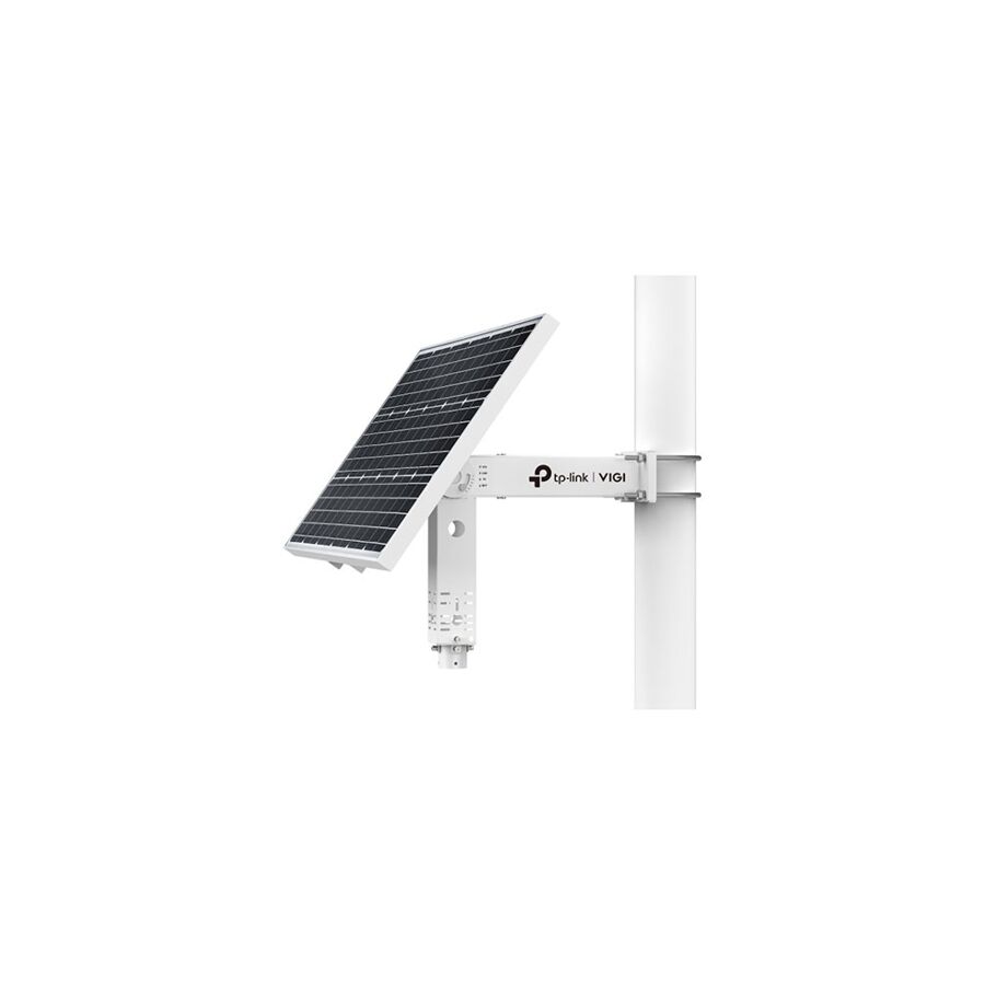
Australia’s energy market has changed dramatically. With some of the highest solar irradiance levels in the world, distributed renewable generation is now a practical and economic solution for homes and commercial facilities. Installing a Solar Panel System is no longer just an environmental decision. It is a long-term infrastructure investment that requires careful engineering and compliance with Australian standards.
A professional Solar Panel System is not simply a collection of panels mounted on a roof. It is a high-voltage DC generation plant integrated with the AC grid. It must comply with AS/NZS 5033 for photovoltaic installation safety and AS/NZS 3000 for electrical wiring requirements.
At SCHNAP Electric Products, we align with Australia’s push toward smarter, safer and more efficient energy systems. We support licensed electricians and solar contractors with compliant balance of system components that help projects meet standards and perform reliably in harsh Australian conditions.
The performance of a Solar Panel System begins with the photovoltaic cell. Modern systems rely on monocrystalline technology, particularly PERC cells.
PERC stands for Passivated Emitter and Rear Cell. These cells include a rear dielectric layer that reflects unabsorbed light back into the silicon wafer. This improves photon capture and increases overall efficiency.
The industry is also shifting toward N-Type silicon cells. These cells are doped with phosphorus rather than boron. N-Type modules are resistant to Light Induced Degradation and perform better at elevated temperatures.
In Australia’s hot climate, temperature performance is critical. Solar modules lose output as temperature rises. N-Type technology reduces this voltage drop, maintaining higher efficiency during summer heat.
Choosing advanced cell technology ensures long-term yield and stronger return on investment.
Solar panels generate Direct Current. This DC energy must be converted into Alternating Current to match the 230V or 400V grid at 50Hz. The inverter performs this function.
In a string inverter system, panels are connected in series. Voltage increases while current remains constant. This approach is cost-effective and common in residential installations.
However, shading on a single panel can reduce output across the entire string. This is often referred to as the Christmas light effect.
To overcome this, installers may use Module Level Power Electronics such as DC optimisers or microinverters. These devices perform Maximum Power Point Tracking at each panel. This allows individual modules to operate independently and maximise system yield under partial shading conditions.
The correct topology depends on site layout, shading profile and budget. Proper design ensures optimal performance over the life of the system.
DC safety is one of the most critical aspects of any Solar Panel System. Unlike AC, DC current does not pass through zero naturally. This means DC arcs can sustain themselves and generate extremely high temperatures.
AS/NZS 5033 requires compliant DC isolators for safe disconnection.
SCHNAP Electric Products DC isolators are engineered with arc control features to extinguish arcs rapidly. Magnetic blow-out mechanisms and arc chutes help prevent fire risk.
These isolators are housed in IP66 rated enclosures made from UV-stabilised materials. This ensures long-term durability under intense Australian sunlight.
Reliable DC isolation protects property, installers and maintenance personnel.
Solar PV cable differs from standard electrical cable. It is double-insulated and cross-linked to withstand high DC voltages and extreme temperature cycles.
Proper cable routing is essential. Cables exposed to UV radiation without protection will degrade over time.
Professional installers route PV cables through UV-resistant conduit and secure them firmly to prevent movement and abrasion.
Roof penetrations must be sealed correctly to maintain weatherproof integrity. Conduit glands and deck sealing components protect against water ingress.
At SCHNAP Electric Products, we support installers with compliant conduit, glands and mounting accessories that improve durability and meet Australian standards.
In larger commercial systems, multiple strings are connected in parallel. Overcurrent protection becomes essential.
A PV combiner box houses DC-rated fuses or circuit breakers that protect individual strings. These devices must be correctly polarised and rated for the array’s open circuit voltage, often up to 1000V DC.
Using AC-rated protection devices in DC applications is unsafe and non-compliant.
SCHNAP Electric Products supplies DC-rated fuse holders and protective components designed for solar applications. Correct protection prevents fault escalation and improves system reliability.
Proper earthing is fundamental in any Solar Panel System. The panel frame and mounting rails must be bonded effectively to reduce lightning risk and ensure safety.
Bonding clamps and earthing hardware must provide secure and corrosion-resistant connections.
Reliable earthing reduces the risk of electric shock and protects system electronics from transient events.
SCHNAP supports solar contractors with earthing accessories that align with Australian wiring standards and deliver dependable performance in coastal and regional environments.
The Australian solar market includes both premium and low-grade products. Grey market panels and uncertified inverters may offer short-term savings but create long-term risk.
Only components listed on the Clean Energy Council approved product list should be installed in compliant systems.
Sourcing through a specialised electrical wholesaler ensures access to genuine, warranty-backed equipment.
SCHNAP Electric Products acts as a reliable supply partner for licensed electricians and EPC contractors. We focus on compliant balance of system components that simplify installation and enhance long-term reliability.
Our strategy supports Australia’s transition to renewable energy by making quality products accessible to trade professionals.
A Solar Panel System is a high-performance electrical asset that demands precision engineering. It integrates advanced semiconductor technology, power electronics and robust mechanical installation.
Selecting efficient PERC or N-Type modules improves yield in Australia’s high-temperature climate. Choosing the correct inverter topology maximises performance under real-world conditions. Ensuring compliant DC isolation and overcurrent protection protects property and lives.
When supported by durable conduit, secure cable management and reliable earthing hardware, the system delivers safe and efficient energy generation for decades.
At SCHNAP Electric Products, we support Australian electricians and solar installers with compliant, practical solutions that help projects meet standards and deliver long-term value. In renewable energy, performance and safety go hand in hand.
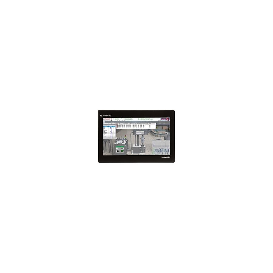
In modern Australian industry, the integration of Information Technology and Operational Technology defines productivity. From food processing plants in Victoria to mining operations in the Pilbara, automation systems rely on reliable human-machine interfaces. The Industrial Touch Screen PC acts as the visual and control gateway between operators and PLC-driven processes.
Unlike consumer-grade computers, industrial environments demand rugged hardware. Dust, vibration, moisture and extreme temperatures quickly destroy standard office equipment. Plastic enclosures crack, cooling fans ingest conductive dust and internal components fail.
An Industrial Touch Screen PC is engineered specifically for these conditions. It delivers reliable SCADA visualisation, real-time monitoring and machine control in environments where downtime is costly.
At SCHNAP Electric Products, we align with Australia’s growing demand for durable, compliant and high-performance automation infrastructure. Industrial PCs form part of that robust ecosystem.
The most critical difference between consumer hardware and industrial computing lies in the enclosure design. Standard PCs rely on active airflow for cooling. In industrial sites, airflow becomes a risk. Dust, oil mist and moisture enter through ventilation openings and cause corrosion or short circuits.
Industrial Touch Screen PCs use fanless thermal architecture. The chassis, typically constructed from finned aluminium, acts as a passive heat sink. Thermal energy is conducted away from the processor and dissipated externally.
This sealed design enables high ingress protection ratings such as IP65 or IP66. In washdown environments such as food and beverage facilities, front bezels may meet IP69K standards. This allows high-pressure and high-temperature cleaning without water penetration.
Sealed construction improves longevity and reduces maintenance requirements. Reliability under harsh Australian conditions is essential for continuous production.
Touch interface performance directly affects operator efficiency. Two dominant technologies exist in industrial applications: resistive and projected capacitive.
Resistive screens operate through pressure applied between two conductive layers. They are functional but have lower optical clarity and reduced durability.
Modern industrial systems favour Projected Capacitive technology, commonly known as PCAP. This technology supports multi-touch functionality and improved visual clarity.
Industrial PCAP screens are engineered differently from consumer versions. They are tuned to operate with gloves and in the presence of moisture. The firmware adjusts electromagnetic sensitivity to register input through protective gear.
The glass surface is chemically hardened, often rated at 7H hardness, to resist scratches from abrasive contaminants. For operators wearing gloves or working in damp conditions, this durability ensures consistent control.
Screen visibility is a key consideration in industrial settings. High-bay LED lighting and outdoor installations create glare and reflection challenges.
Standard screens operate around 250 nits brightness. Industrial units often provide 1000 nits or more for sunlight readability.
Optical bonding further enhances performance. This process removes the air gap between the LCD panel and touch glass by filling it with a transparent resin.
Eliminating this gap reduces internal reflection and parallax error. It also prevents condensation forming inside the display when temperature fluctuates between hot days and cold nights.
In regional Australian environments, where temperature extremes are common, optical bonding ensures long-term display clarity.
Industrial machinery generates vibration. Mechanical hard drives fail quickly under these conditions.
Industrial Touch Screen PCs use solid state storage. Industrial-grade SSDs have no moving parts and are often soldered directly to the board. This prevents connectors from loosening under vibration.
RAM modules are secured firmly to prevent data errors. The result is improved resistance to G-force and shock.
For mining operations, stamping presses and mobile machinery, this solid-state architecture ensures stable system operation and prevents data corruption.
Reliable storage protects SCADA configurations and production data.
Industrial power environments are rarely clean. Voltage spikes, sags and transient surges occur due to large inductive loads switching on and off.
Industrial PCs are designed with wide-range DC inputs and built-in surge protection. However, additional external protection improves resilience.
At SCHNAP Electric Products, we support complete installation integrity. DIN-rail surge diverters protect against transient events. DC UPS modules ensure graceful shutdown during blackouts, preventing database corruption and system crashes.
Reliable power management reduces downtime and protects critical automation infrastructure.
Proper installation ensures both ergonomics and protection. Industrial Touch Screen PCs are often mounted on control cabinets, swing arms or dedicated operator consoles.
Heavy-duty VESA mounts and articulated arms provide stable positioning without sagging. Secure mounting improves operator comfort and reduces mechanical stress.
Cable routing is equally important. Power, Ethernet and USB cables must be protected from washdown exposure and mechanical damage.
Flexible conduit and IP-rated cable glands seal cable entry points and maintain ingress protection integrity.
SCHNAP Electric Products provides supporting accessories that help electricians and automation integrators complete installations efficiently and safely.
Industrial automation systems require long lifecycle hardware. Consumer electronics change rapidly and may become obsolete within a year.
Industrial Touch Screen PCs are typically built on chipsets guaranteed for extended availability. Long lifecycle support ensures replacement parts remain available for five to seven years or more.
For plant managers and automation engineers, consistent hardware availability reduces re-engineering costs.
Sourcing through a specialised electrical wholesaler ensures verified compliance and reliable supply. SCHNAP supports trade professionals with dependable stock and responsive service.
Australia’s manufacturing, mining and food processing sectors depend on reliable automation. Industrial Touch Screen PCs bridge human operators and machine logic.
They provide visibility into production metrics, safety systems and quality control processes.
By combining fanless cooling, high ingress protection, durable touch interfaces and robust mounting solutions, these systems support continuous operation in harsh conditions.
SCHNAP Electric Products aligns with this demand for durability and performance. Our strategy focuses on supporting licensed electricians, automation contractors and project managers with reliable infrastructure components that simplify installation and enhance productivity.
The Industrial Touch Screen PC is not simply a display. It is a mission-critical automation interface engineered for resilience.
Through fanless thermal management, IP66 washdown protection, PCAP touch technology and solid-state reliability, it withstands the challenges of Australian industrial environments.
When supported by proper power protection, secure mounting and compliant installation practices, it delivers long-term performance and operational confidence.
At SCHNAP Electric Products, we support Australia’s industry with practical, durable and compliant solutions that help trade professionals complete projects on time and maintain reliability. In automation engineering, hardware resilience defines system success.
Indoor Air Quality is now a major focus in modern Australian homes. With rising awareness of asthma, dust sensitivity and allergens, traditional portable vacuum cleaners are no longer seen as the best solution for premium builds. Many portable units recirculate fine dust particles back into the room. This undermines cleaning performance and affects long-term air quality.
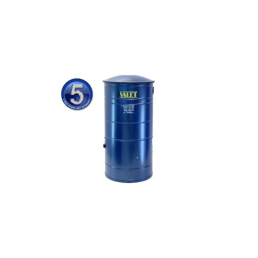
A ducted vacuum system solves this problem by removing dust completely from the living space. At the heart of that system is the Central Vacuum Power Unit. Installed in a garage, plant room or basement, this stationary appliance provides industrial-grade suction and exhausts vacuumed air outside the habitable area.
For electricians and builders aligned with SCHNAP’s strategy of delivering smarter residential infrastructure, the central vacuum power unit represents a practical upgrade in both hygiene and long-term property value.
The key difference between a central power unit and a portable vacuum lies in the motor design. Portable units typically use a thru-flow motor, where dusty air passes directly over the motor windings for cooling. Over time, fine particles damage insulation and bearings.
Professional central units use a tangential bypass motor. In this configuration, the dirty vacuum air is completely separated from the clean cooling airflow. A dedicated fan cools the motor while a separate airflow path handles debris.
This separation improves longevity and reliability. It prevents abrasive dust from eroding motor components. These motors are also larger in diameter, commonly 5.7 inch or 7.2 inch, allowing for larger impellers.
The result is significantly higher sealed suction, known as water lift, and stronger airflow. This power is essential for pulling debris through long pipe runs of up to fifty metres of PVC ducting.
For high-end residential projects, this performance ensures consistent suction at every inlet point.
Filtration design directly affects efficiency and maintenance. Two main systems dominate the market: cyclonic and bagged.
Cyclonic filtration uses centrifugal force to separate dust from the airstream. The intake is angled to create a vortex inside the collection chamber. Heavier particles are forced outward and drop into the dust bucket.
This design maintains airflow performance even as the container fills, since no physical filter blocks the intake. Hybrid systems often combine cyclonic separation with secondary HEPA filtration or a self-cleaning membrane.
Bagged systems, by contrast, rely on disposable filter bags to trap debris. While simple, airflow may reduce as the bag fills.
For Australian homes focused on long-term efficiency and lower maintenance, cyclonic systems are often preferred.
Correct sizing of the Central Vacuum Power Unit is critical. The performance metric commonly referenced is Airwatts. This combines airflow and sealed suction into a single measurement.
However, relying only on Airwatts can be misleading. In large single-level homes with long pipe runs, water lift is the more important factor. High water lift ensures debris can travel against friction and gravity over extended distances.
In compact double-storey homes, airflow volume may take priority to ensure rapid cleaning across multiple inlets.
Engineers must calculate pipe length, number of bends and total inlet count. Suction at the furthest inlet should remain above a minimum performance threshold to effectively power turbo heads and electric brushes.
Correct sizing prevents underperformance and ensures homeowner satisfaction.
While the power unit delivers suction, a low-voltage control network activates the system. A 2-core 24V control cable runs alongside the PVC ducting.
When the hose is inserted into a wall inlet, the circuit closes and signals a relay in the power unit to energise the motor.
The integrity of this control wiring is essential. Damage during rough-in stages can cause intermittent faults or continuous running.
Licensed electricians should secure and protect the control wiring properly. SCHNAP Electric Products provides cable management accessories that support tidy and protected installations.
Reliable low-voltage connections ensure long-term system operation without call-backs.
A Central Vacuum Power Unit is a high-load appliance, often drawing between 1500W and 2000W. It must be installed on a dedicated circuit to prevent nuisance tripping.
Electrical protection is critical for safety and compliance.
SCHNAP Electric Products RCBOs provide residual current and overcurrent protection. Installing a dedicated RCBO in the main switchboard protects both the motor and fixed wiring.
A weatherproof isolator near the unit allows safe local disconnection for maintenance tasks such as emptying the dust bucket or replacing motor brushes.
This approach aligns with SCHNAP’s strategy of supporting electricians with compliant, reliable and easy-to-install protection solutions.
The mechanical installation of the power unit and ducting affects noise levels and long-term durability. PVC ducting must be secured firmly to framing members. Poorly supported pipework can cause vibration and rattling during operation.
Conduit straps and ducting supports ensure rigid installation. A muffler system may also be added to reduce exhaust noise.
Professional installation practices enhance system performance and homeowner satisfaction.
For builders delivering premium homes, these details distinguish a high-quality ducted system from a basic installation.
The market includes low-cost units with exaggerated horsepower claims and lightweight plastic construction. These products often lack verified motor performance curves and may fail prematurely.
For residential projects aligned with long-term reliability, sourcing through a reputable electrical wholesaler is essential.
SCHNAP Electric Products supports trade professionals with quality-assured components and dependable supply. Our focus is helping electricians complete installations on time while maintaining performance standards.
By combining reliable power units with compliant electrical protection and secure ducting accessories, contractors can deliver systems that meet modern expectations for hygiene and efficiency.
The Central Vacuum Power Unit is a core component of modern residential infrastructure. It removes dust and allergens completely from the living space, improving indoor air quality and supporting healthier homes.
Through tangential bypass motor technology, cyclonic filtration and correct system sizing, ducted vacuum systems deliver powerful and consistent performance.
When supported by dedicated electrical protection, low-voltage control wiring and secure mechanical installation, the system operates safely and reliably for years.
At SCHNAP Electric Products, we support Australian electricians and builders with compliant, practical solutions that enhance residential projects. Cleaner air, smarter infrastructure and dependable installation standards define today’s premium homes.
In modern Australian commercial spaces, power access is no longer optional. Agile workspaces, hot-desking offices, airport lounges and hospitality venues all demand seamless device charging without clutter. Traditional General Power Outlets often lead to tangled cables, bulky adapters and unsafe trip hazards.
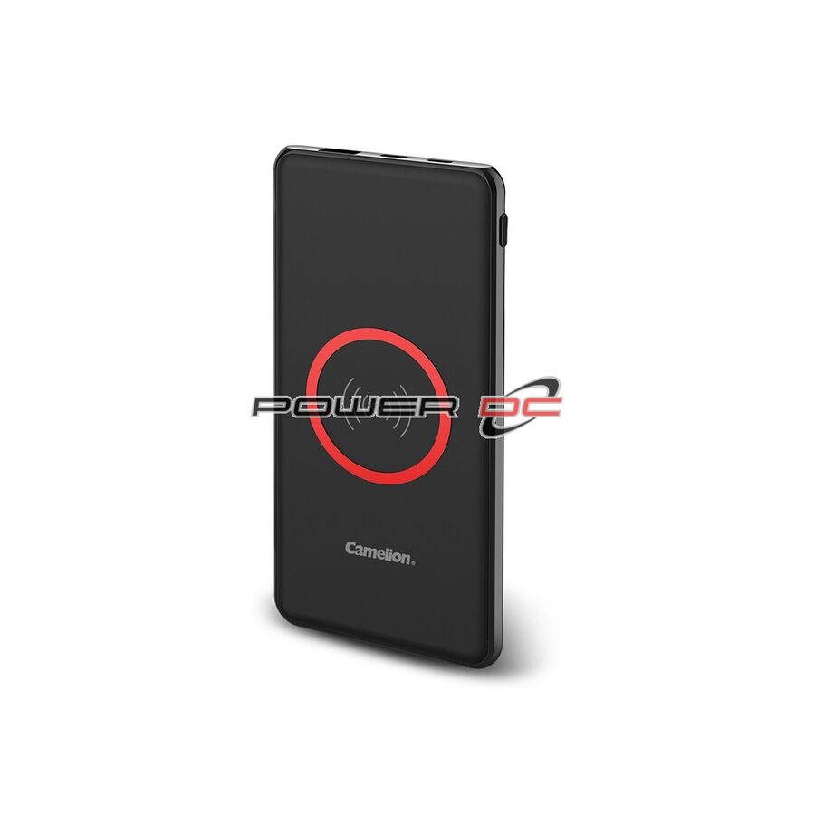
The integrated Wireless Charger has become the engineered solution. It delivers convenient device power while maintaining a clean, professional aesthetic. For commercial fitouts, this is no longer a luxury feature. It is part of essential infrastructure.
At SCHNAP Electric Products, we align with Australia’s shift toward smarter, more efficient workspaces. Wireless charging supports productivity, improves presentation and enhances customer experience while keeping installations compliant and safe.
Wireless charging is based on electromagnetic induction. The charger contains a primary copper coil that generates an oscillating magnetic field when energised. When a compatible device is placed on the surface, a secondary coil inside the device captures this energy and converts it into DC power for battery charging.
Modern systems operate under the Wireless Power Consortium Qi standard. These chargers communicate dynamically with the device. They negotiate the appropriate power level, typically between 5W and 15W.
This negotiation ensures efficient power transfer while protecting battery health. If alignment is imperfect or the surface thickness increases the vertical gap between coils, the charger adjusts its operating frequency to maintain efficiency.
High-quality chipsets are critical. Poorly engineered units suffer from excessive heat loss and slow charging speeds. For commercial installations, reliability and consistency matter.
In public environments, safety is critical. Metallic objects such as keys or coins can accidentally be placed on a charging pad. Inferior chargers may induce eddy currents in these objects, creating heat and potential burn risk.
Qi-certified wireless chargers include Foreign Object Detection. The internal controller continuously monitors power transfer. If it detects abnormal energy absorption, the system instantly shuts down the magnetic field.
This safety mechanism is essential for commercial spaces in Australia. It protects users and reduces liability risk.
At SCHNAP, we focus on supplying compliant and tested products that meet Australian EMC and RCM requirements. Safety is non-negotiable.
Installing a Wireless Charger into a boardroom table or café counter requires precision. The inductive process is not fully efficient. Energy losses appear as heat.
If the unit is embedded into timber or stone without ventilation, internal temperatures can rise. This can cause thermal throttling and slow charging performance.
Professional installation often involves routing the underside of the surface to reduce thickness. For sub-surface chargers, surface thickness should typically be under 3 mm. Through-desk grommet style units offer a flush finish while allowing airflow beneath the surface.
Thermal management protects both the charger and the device. It ensures long-term reliability in high-usage environments.
Proper cable management is equally important. Low-voltage cables should be secured neatly under the desk to prevent drooping and strain. SCHNAP Electric Products cable management solutions support clean and professional installations, aligning with our goal of making trade life easier.
A Wireless Charger is only the final point in a broader power system. Most modern fast-charging pads require USB-C Power Delivery.
USB-C PD enables negotiation of higher voltages such as 9V or 12V. Connecting a 15W charging pad to an outdated 5W USB-A source results in reduced performance.
Commercial fitouts must consider upstream power delivery. Centralised DC rails or soft-wiring systems provide flexibility. Soft-wiring interconnects allow office layouts to change without full electrical rework.
This flexibility supports growing businesses and evolving workspaces. SCHNAP’s product ecosystem ensures electricians can source compatible components for reliable installations.
Low-cost wireless charging pads often generate excessive Electromagnetic Interference. This interference can disrupt Wi-Fi networks or Bluetooth devices in nearby workstations.
Professional installations require WPC-certified chargers that comply with Australian EMC standards. RCM compliance confirms suitability for local conditions.
Quality hardware reduces interference risk and ensures compatibility with current device standards including MagSafe and Qi2.
For facility managers and shopfitters, procurement through a trusted electrical wholesaler ensures verified compliance. SCHNAP prioritises certified products that meet real-world commercial requirements.
Wireless Chargers are now common in corporate boardrooms, co-working spaces, cafés and hospitality venues. They enhance customer experience while maintaining a clean design.
In offices, integrated chargers support agile working and reduce clutter. In hospitality settings, they provide a premium touchpoint that improves brand perception.
For electricians and fitout contractors, offering integrated wireless charging adds value to projects. It demonstrates attention to modern user needs while maintaining compliance and safety standards.
SCHNAP supports trade professionals with practical solutions, competitive pricing and reliable supply. We understand that efficient sourcing and dependable products help projects stay on schedule.
SCHNAP Electric Products focuses on supporting licensed electricians and commercial contractors. We supply products that simplify installation and enhance project outcomes.
Wireless charging infrastructure fits within our broader strategy of smarter power distribution, practical innovation and customer-focused service.
By combining compliant wireless chargers with structured cable management and flexible power delivery solutions, electricians can deliver workspaces that are efficient, modern and safe.
Our goal is to provide reliable products that help trade professionals complete jobs on time and maintain profitability.
The Wireless Charger has evolved from a consumer novelty into a core component of modern commercial fitouts. It delivers seamless device power while preserving clean aesthetics and safe environments.
Through Qi-certified inductive technology, Foreign Object Detection and proper thermal management, commercial installations can achieve reliable and efficient charging performance.
When supported by robust power delivery infrastructure and professional installation practices, wireless charging becomes long-term infrastructure rather than temporary convenience.
At SCHNAP Electric Products, we help Australian electricians and contractors integrate smarter power solutions into today’s agile workplaces. Clean design, safe operation and dependable performance define successful commercial projects. Wireless charging is now part of that standard.
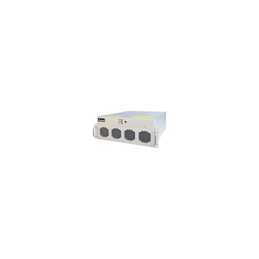
The electrical profile of Australian industrial and commercial facilities has changed permanently. Where once the dominant loads were linear and predictable, modern installations are now saturated with non-linear electronic equipment. Variable Speed Drives control motors with precision, LED drivers power vast lighting arrays, UPS systems protect critical loads, and EV chargers inject high-power switching currents into local networks. These technologies improve efficiency and controllability, but they introduce harmonic distortion as a by-product of their operation.
Harmonics are not a minor side effect. They deform the current waveform, elevate neutral currents, overheat transformers, create nuisance tripping, and shorten the life of sensitive electronics. In large facilities, unmanaged harmonic distortion can result in failed audits, breached network connection agreements, and costly downtime. The engineering response adopted across Australian industry is the active power filter module. This device does not merely suppress symptoms. It dynamically neutralises harmonic currents in real time, restoring electrical stability at the source.
An active power filter module operates on a fundamentally different principle to passive harmonic filters. Passive solutions rely on fixed inductors and capacitors tuned to specific harmonic frequencies. While effective under stable load conditions, they lack adaptability and can resonate with the network under changing conditions.
Active filters operate dynamically. Using high-accuracy current transformers, the module continuously measures load current flowing through the supply. A digital signal processor analyses this waveform in real time, separating the fundamental fifty-hertz component from the harmonic content using mathematical techniques such as Fast Fourier Transform analysis.
Once the harmonic signature is identified, the filter generates an equal and opposite current waveform using its internal power electronics. This compensating current is injected into the system at the point of connection. When combined with the distorted load current, the harmonics cancel each other out, leaving a clean sinusoidal current drawn from the upstream supply. This process occurs within microseconds and adapts instantly as loads fluctuate. Whether a drive ramps up, a lift starts, or an EV charger engages, the filter responds without delay.
Australian electricity networks operate under strict power quality requirements. AS/NZS 61000.3.6 defines permissible harmonic emission limits for installations connected to medium and high voltage networks. Distribution Network Service Providers enforce these limits to protect shared infrastructure and ensure equitable network performance.
Excessive Total Harmonic Distortion can lead to penalties, enforced remediation, or disconnection. Active power filter modules are specifically engineered to address these requirements. High-performance units mitigate harmonics across a wide frequency spectrum, often up to the fiftieth harmonic order. By targeting dominant harmonic components such as the fifth, seventh, eleventh, and thirteenth orders, facilities can reduce THDi at the point of common coupling to acceptable levels.
This capability is particularly important in data centres, hospitals, mining facilities, and commercial towers where non-linear loads dominate and network compliance is closely monitored.
Modern active power filter technology has evolved towards modular construction. Instead of large standalone cabinets, current systems use compact modules that integrate directly into switchboards. These modules are typically rated in discrete current capacities and can be paralleled to meet site requirements.
This modularity delivers several operational advantages. Capacity can be scaled precisely to match measured harmonic load rather than over-sizing equipment. Redundancy is inherent. If one module is taken offline for maintenance, remaining modules continue operating, preserving partial harmonic mitigation. As facilities expand or load profiles change, additional modules can be installed without redesigning the entire system.
For Australian sites planning staged expansion, this approach provides future-proofing while maintaining continuous compliance.
An active power filter module is not limited to harmonic suppression. It also functions as a comprehensive power quality conditioner. One key capability is dynamic power factor correction.
Traditional capacitor banks correct displacement power factor in fixed steps. They cannot respond quickly to load variation and do not address distortion power factor caused by harmonics. Active filters correct both simultaneously. They inject reactive current dynamically, maintaining a near-unity power factor under all operating conditions. This reduces apparent power demand, lowers current draw, and improves utilisation of transformers and cabling.
Additionally, active filters can balance three-phase loads. In buildings with uneven single-phase loading, neutral currents can become dangerously high. By redistributing current on the supply side, the filter presents a balanced load to the upstream network, reducing thermal stress and improving overall system stability.
Integrating an active power filter module into a main switchboard requires careful attention to measurement accuracy, protection coordination, and thermal management. The current transformers feeding measurement data to the filter are critical components. Inaccurate sensing leads to incorrect compensation and reduced effectiveness.
High-accuracy CTs ensure the digital processor receives precise current data. Protection of the module itself is equally important. Active filters handle significant energy and must be isolated safely in the event of internal faults. Appropriate upstream protection devices ensure faults are contained without affecting the broader installation.
Mechanical integration also matters. Modular filters are often connected to busbars using flexible conductors that accommodate thermal expansion and vibration while allowing rapid replacement. This design supports safe maintenance and minimises downtime.
This is where infrastructure components from Schnap Electric Products are commonly specified. Precision CTs, high-capacity protection devices, and flexible busbar solutions support accurate sensing, safe isolation, and practical switchboard assembly.
Active power filter modules generate heat during operation due to high-frequency switching within their power electronics. Efficient heat removal is essential to protect internal components and maintain long-term reliability.
Switchboard enclosures housing active filters must provide adequate airflow and filtration. Poor thermal design leads to elevated internal temperatures, accelerated ageing of components, and increased failure rates. In Australian environments, airborne dust compounds this risk by insulating heat sinks and contaminating electronics.
Professional installations incorporate forced ventilation and filtration strategies to maintain clean, controlled internal conditions. Proper cabinet design is a fundamental part of system reliability, not an optional accessory.
Selecting an active power filter module is not a commodity purchase. Performance depends on switching frequency, control algorithms, thermal design, and measurement accuracy. Low-quality units may introduce audible noise, respond too slowly to load changes, or fail prematurely under sustained operation.
Consulting engineers and switchboard manufacturers typically specify active filters based on detailed site audits. Harmonic spectra, load diversity, and expansion plans inform module sizing and configuration. Procuring equipment through specialised electrical wholesaler ensures access to verified products with documented performance and local technical support.
A controlled supply chain also ensures compatibility between modules, sensing equipment, protection devices, and switchboard hardware, reducing installation risk and commissioning time.
The active power filter module is a cornerstone of modern Australian electrical infrastructure. It enables facilities to embrace efficient, electronically controlled loads without sacrificing power quality or regulatory compliance. By dynamically cancelling harmonics, correcting power factor, and balancing phase loads, it restores stability to networks under increasing strain. When specified correctly and integrated with precision infrastructure, the active power filter module transforms a polluted supply into a clean, efficient power system. In the domain of power quality, control is not optional. It is the foundation of performance and reliability.
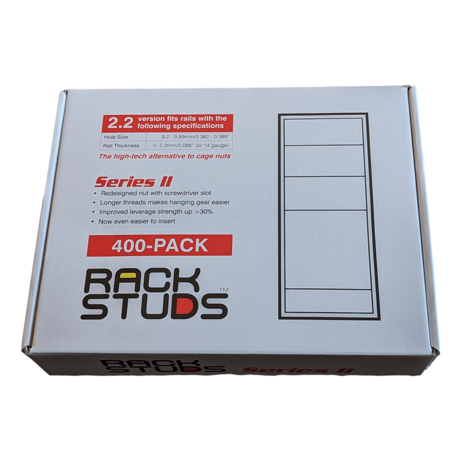
In Australian data centres, industrial switchrooms and communications shelters, structural integrity is critical. Every server, UPS, switch or control module depends on the strength of its mounting interface. The smallest fastening component often determines the reliability of the entire cabinet.
Rack mounting studs are engineered fasteners designed for secure installation of equipment into 19-inch racks compliant with EIA-310 standards. Unlike standard rack screws, studs provide a fixed male thread that allows equipment to be positioned safely before final tightening.
While often overlooked as a minor consumable, rack mounting studs directly affect load capacity, vibration resistance, earthing continuity and long-term reliability. In high-density Australian environments, that performance difference matters.
Modern racks house heavy equipment. A 4U UPS can exceed 50 kg. Large blade servers and battery modules also carry significant weight.
Using loose screws and cage nuts requires installers to hold equipment in place while aligning threads. This increases risk of cross-threading, equipment damage and manual handling strain.
Rack mounting studs change the process. The installer secures the studs into the rack rail first. Equipment is then hung onto the fixed studs before nuts are tightened.
This approach improves safety and alignment. It transfers weight directly onto the shear plane of the stud immediately. The equipment becomes supported rather than suspended during installation.
In vibration-prone environments such as mining sites or industrial plants, studs also allow the use of nyloc or serrated flange nuts. These provide greater resistance to loosening compared to standard rack screws.
The performance of mounting hardware is governed by tensile strength and shear capacity. High tensile rack mounting studs are commonly manufactured to Grade 8.8 equivalent or higher. This ensures reliable performance under static load and dynamic stress.
In a loaded rack, the force applied is not purely vertical. Transport movement, seismic vibration and cable strain introduce lateral forces.
Studs provide improved load distribution across the rack rail. The continuous threaded shaft creates stronger engagement compared to shorter screw threads.
When properly torqued, they maintain clamping force over long service periods. This reduces the risk of loosening and equipment misalignment.
For mission-critical infrastructure, mechanical stability directly protects uptime.
The EIA-310 standard defines the hole spacing in 19-inch racks. The repeating 15.875 mm – 15.875 mm – 12.7 mm pattern governs vertical equipment placement. Studs require precise alignment with this spacing. Unlike floating cage nuts, fixed studs offer minimal adjustment.
This demands accurate rack manufacturing tolerances. The benefit is improved precision.
Equipment mounted on studs becomes self-centering. This is especially important in hot aisle and cold aisle containment systems. Even small misalignments can create airflow gaps that reduce cooling efficiency.
Accurate mounting supports both mechanical integrity and airflow performance.
In Australia, compliance with AS/NZS 3000 is mandatory. All metallic cabinet components must be bonded to earth.
Powder-coated rails present an insulating barrier. Standard screws may not adequately penetrate coatings.
Quality rack mounting studs often include serrations under the head. These bite through paint to create metal-to-metal contact. Star washers are also used to ensure low impedance bonding.
This bonding path connects equipment chassis to the rack frame and ultimately to the main earth bar.
Reliable earthing protects personnel from hazardous touch voltages during fault conditions. It also supports electromagnetic compatibility by reducing stray potential differences within the cabinet.
In critical environments, earthing continuity is not optional.
Material choice depends on installation environment. For climate-controlled data centres, zinc-plated steel studs provide suitable corrosion resistance and high strength.
However, in coastal regions, wastewater facilities or high humidity environments, corrosion risk increases.
In sensitive electronics applications, engineers may also consider the potential for zinc whiskers. These microscopic filaments can detach and cause short circuits.
For corrosive or high-risk environments, 304 or 316 stainless steel studs are preferred. These provide superior environmental durability.
Installers must manage thread galling when using stainless hardware. Anti-seize compounds or specialised coatings reduce the risk of cold welding during tightening. Correct material selection extends equipment lifespan and reduces maintenance risk.
Heavy copper cabling introduces additional mechanical stress. Poor strain relief can apply torque to mounting points. Rack mounting studs must work alongside cable management systems. Strain relief bars, P-clips and cable saddles reduce load transfer to the stud.
This maintains alignment of servers and switchgear. It also prevents vibration from cable movement.
Mechanical stability depends on the complete fastening system, not the stud alone. Nuts, washers and isolation components must match thread tolerance and load rating.
A high-quality stud paired with inferior hardware becomes a weak link.
The fastener market includes low-grade alloys that strip under torque or fail under load.
A single failed stud can cause equipment collapse within the rack. Damage costs can be significant.
Professional electrical wholesaler supply batch-tested, high tensile hardware. Thread consistency, plating thickness and strength ratings are verified.
Quality control protects installers and infrastructure managers from mechanical failure risk.
For specialised applications, nylon isolation washers may be used to electrically isolate certain chassis units. This can assist in noise reduction or specific grounding protocols.
Reliable procurement ensures consistency across large infrastructure projects.
Australia’s data infrastructure spans metropolitan data centres, mining facilities, telecommunications towers and industrial automation sites. Each environment presents unique mechanical and environmental demands.
High temperatures, vibration and remote access conditions increase the importance of robust fastening systems.
Rack mounting studs provide improved installation safety, stronger load support and better long-term reliability.
They transform cabinet assembly from a basic mounting task into a controlled structural system.
Rack mounting studs are foundational components of secure server and switchboard installations. They improve installer safety, enhance load stability and support compliance with EIA-310 and Australian wiring standards.
By prioritising high tensile strength, correct material selection and reliable earthing continuity, infrastructure managers reduce mechanical failure risk.
In digital infrastructure, uptime depends on every connection point. The fastener defines the failure threshold.
Choosing engineered rack mounting studs ensures that cabinets operate not as simple enclosures, but as structurally sound systems built for performance, safety and long-term reliability in demanding Australian environments.
In Australia’s rapidly expanding digital economy, from hyperscale facilities in Western Sydney to edge nodes in regional mining and industrial operations, cooling is the primary operational constraint. As rack densities increase beyond 10kW and move toward 20kW per rack, enclosure design becomes part of the cooling system itself.
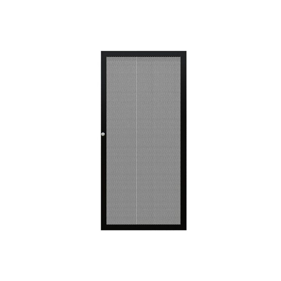
A perforated steel door is no longer just a cabinet accessory. It is a performance-critical airflow component. Unlike glass or solid steel doors that restrict intake and exhaust flow, a perforated steel door enables continuous air exchange while maintaining physical security.
In high-density server environments, thermodynamics dictates uptime. Heat must move efficiently from equipment to containment aisles. A poorly ventilated door increases static pressure and forces server fans to operate at higher RPM. That additional energy draw increases internal heat and reduces overall efficiency.
A properly engineered perforated steel door eliminates this restriction. It supports maximum airflow permeability while maintaining structural strength and controlled access.
The performance of a perforated steel door is measured by its open area percentage. This represents the ratio of perforated openings to total surface area.
Earlier round-hole designs typically achieved less than 50% open area before structural strength was compromised. Modern engineering uses hexagonal perforation geometry.
The hexagon is structurally efficient. It maximises airflow while maintaining tensile strength in the remaining steel web. Professional-grade doors achieve between 63% and 81% open area.
This high permeability reduces static pressure across the rack face. Servers can pull required CFM without excessive resistance. Lower fan speeds reduce energy consumption and decrease secondary heat generation.
A high open area hex mesh allows servers to operate as if installed in open-frame systems while still maintaining full physical protection.
Removing material weakens steel. That is unavoidable.
To compensate, perforated steel panels are welded into reinforced tubular frames or formed with stiffening ribs. This restores torsional rigidity and prevents flexing during operation.
A door that twists under load causes lock misalignment and poor sealing. In busy data halls, doors must withstand accidental impacts, cable pressure, and repeated opening cycles.
Many high-performance doors incorporate a subtle curved profile. This is not aesthetic alone. The curvature increases structural modulus and improves resistance to inward deflection.
Heavy-gauge steel combined with reinforced framing ensures durability without sacrificing airflow performance.
In colocation environments, cabinet security defines tenant boundaries. The door must support advanced locking solutions beyond standard keyed cylinders.
Modern installations require electronic swing handles, RFID access, biometric readers, or integration with building management systems.
Multi-point locking systems secure the door at top, centre, and bottom. This prevents corner prying and improves forced-entry resistance.
The perforated steel door becomes the primary security demarcation point. It must support compliance frameworks such as ISO 27001 without compromising airflow.
Mechanical strength and access control integration must operate together. Security cannot restrict cooling, and cooling cannot weaken security.
A steel door is a conductive surface. Proper earthing is mandatory. Relying on hinges for continuity is poor engineering practice. Paint, grease, and wear create resistance.
Australian installations must comply with AS/NZS 3000 requirements for reliable protective earthing. Professional systems use braided earth straps between door and cabinet frame.
This ensures a low impedance path to ground during fault conditions. It also assists in reducing electromagnetic interference from switching power supplies.
Correct bonding protects personnel from touch potentials and improves electromagnetic compatibility within the rack environment.
Perforation also supports visual monitoring. Facility managers must see server status LEDs without opening the cabinet. Opening doors disrupts airflow patterns and containment efficiency.
Matte black powder-coated finishes reduce glare and reflection. The contrast between dark mesh and illuminated LEDs provides immediate equipment visibility.
High-quality electrostatic powder coating resists scratching and prevents chipping. This avoids conductive debris entering the airflow path.
Durability of finish is not cosmetic. It directly affects long-term operational integrity.
Not all perforated steel doors are engineered equally. Low-cost alternatives often use thin mesh resembling fly-screen material. These deform under pressure and lack structural support.
Inferior products compromise both airflow and physical security. Professional procurement requires heavy-gauge steel construction, verified open area specifications, and compatibility with EIA-310 rack standards.
Reputable electrical wholesaler supply certified enclosures designed for high-density cooling performance. They provide compatible hinge kits, locking systems, stiffening components, and retrofit solutions.
Upgrading existing cabinets with high open area doors is often more cost-effective than replacing entire racks.
Supply chain assurance ensures long-term reliability and compatibility with next-generation hardware demands.
Australia’s climate conditions, high ambient temperatures, and expanding digital workloads make cooling efficiency critical.
Energy costs continue to rise. Reducing fan load across thousands of servers delivers measurable operational savings.
Improved airflow reduces thermal hotspots, extends equipment lifespan, and enhances reliability.
A perforated steel door becomes a passive cooling multiplier. It supports containment strategies, improves airflow management, and maintains security compliance.
It is not simply a mesh panel. It is a thermodynamic interface between equipment and cooling architecture.
The perforated steel door is the airflow gateway of modern server infrastructure. By maximising open area through hexagonal geometry, maintaining structural rigidity through reinforced framing, and ensuring compliant earthing and secure locking integration, it enables efficient and secure rack operation. In high-density environments, every restriction increases energy consumption and risk. A properly engineered perforated steel door allows servers to breathe freely while maintaining controlled access and structural integrity.
For Australian data centres, mining operations, industrial facilities, and enterprise server rooms, this balance between airflow and security defines performance. When cooling efficiency and physical protection must coexist, the perforated steel door becomes essential infrastructure rather than optional hardware.
In Australia’s data centre and industrial IT environments, infrastructure reliability starts at ground level. From hyperscale facilities in Western Sydney to edge cabinets in mining and energy sites, the physical base of a rack installation directly affects safety, airflow, and long term performance.
A fully populated 42U or 45U rack can exceed 1000 kilograms. Servers, storage arrays, UPS systems, and network hardware create a concentrated static load. When this weight is transferred through four small corner points onto a raised floor tile or slab, structural stress increases significantly.
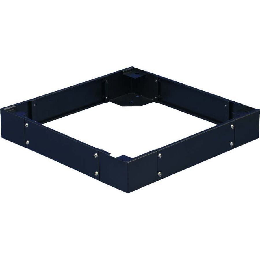
The server rack plinth is the engineered solution. It is not simply a cosmetic skirt. It is a load management, airflow control, and cable logistics interface between the rack and the building.
Without a plinth, the weight of a rack is transferred through levelling feet or castors. This creates four point loads. In raised access floors, these loads can exceed recommended tile deflection limits.
A plinth spreads the weight across a wider footprint. Manufactured from folded heavy gauge steel, it forms a rigid perimeter base. The load is distributed more evenly across floor stringers and support pedestals.
This distribution reduces structural stress and improves long term floor integrity. It also improves rack stability when heavy equipment is extended forward.
When technicians slide out UPS battery trays or blade servers, the centre of gravity shifts outward. This introduces forward tipping forces. A bolted plinth increases the anti tilt threshold. It provides a secure anchoring interface to the slab beneath the raised floor.
In industrial or seismic environments, this anchoring capability becomes critical. Stability is not optional in mission critical installations.
In professional rack deployments, the area beneath the cabinet is the primary cable entry zone. Power feeds and structured data cabling rise from below the floor into the rack.
Without a plinth, cables must turn sharply at the cabinet base. Tight bends can compromise data performance. AS/NZS 3080 specifies minimum bend radius requirements for structured cabling.
The plinth creates a dedicated marshalling zone. Typically 100mm to 200mm high, this void allows cables to sweep gradually into vertical managers. It protects fibre and copper from mechanical stress.
This space also allows storage of service loops. Service loops provide future flexibility. They allow retermination or hardware relocation without repulling cable from patch panels or distribution frames.
By protecting bend radius and cable integrity, the plinth contributes to long term network reliability.
Modern data centres rely on controlled airflow strategies. Cold aisle containment depends on separation between supply air and exhaust air.
A rack mounted on castors leaves a gap between the frame and the floor. This gap becomes a leakage path. Conditioned cold air can bypass servers. Alternatively, hot air can recirculate under the rack.
A server rack plinth seals this perimeter. Solid kick plates close the gap between rack and floor. This preserves static pressure in the cold aisle.
Cable entry openings must still be managed carefully. Installers often integrate brush strip modules to allow cables through while maintaining airflow control. These accessories are commonly sourced through Schnap Electric Products to ensure compatibility and durability.
By limiting bypass airflow, the plinth improves cooling efficiency. Reduced air leakage lowers HVAC load and improves energy performance.
Data halls are active environments. Cleaning equipment, trolleys, and maintenance carts move constantly through aisles.
Exposed levelling feet and lower rack frames are vulnerable to impact. A steel plinth acts as a protective bumper. It absorbs minor collisions and protects both the rack structure and sensitive cabling beneath.
This protection is particularly important where power distribution units and fibre trunks enter from below. Mechanical damage at the base of a rack can compromise entire network segments.
Beyond function, the plinth also provides a clean aesthetic finish. It conceals cable entry zones and floor cut-outs, creating a professional and organised environment.
Electrical bonding is mandatory under AS/NZS 3000. Any exposed metal component must be connected to the building earth system.
The plinth must be equipotential bonded to the rack frame and main earth bar. Flexible earth braids accommodate any slight movement while maintaining continuity.
Proper bonding reduces the risk of electrostatic discharge. It also ensures fault currents have a defined path to ground.
When combined with appropriate bonding hardware and cable glands, the plinth becomes part of the electrical safety system rather than just a mechanical accessory.
Rack manufacturers vary in footprint dimensions. Common widths include 600mm and 800mm. Depths range from 1000mm to 1200mm or more.
A correctly matched plinth must align precisely with the rack mounting points. Poor fitment leads to misalignment and instability.
Professional plinth kits are designed for specific rack footprints. Adjustable mounting holes allow fine alignment during installation. Once positioned, the rack and plinth are bolted together to form a unified structure.
Accuracy at this stage ensures long term stability, especially in high density deployments.
Generic base skirts often lack structural rigidity. Light gauge steel can deform under heavy loads. Inferior finishes may corrode in humid environments.
Sourcing through specialised electrical wholesalers ensures dimensional compatibility and verified load capacity. Proper mounting hardware, cage nuts, and floor anchors are included or available as matched accessories.
High quality plinth systems support both raised floor and slab installations. They are designed for long term infrastructure rather than temporary fit-outs.
The server rack plinth is the structural foundation of a professional cabinet installation. It distributes weight, stabilises heavy racks, protects cable entry, and improves airflow efficiency.
By addressing load management, thermal containment, cable logistics, and physical protection in a single engineered component, it enhances both safety and performance.
In Australian data centres and industrial IT environments, infrastructure reliability begins at the floor. The server rack plinth ensures that everything built above it rests on a stable, compliant, and engineered base.
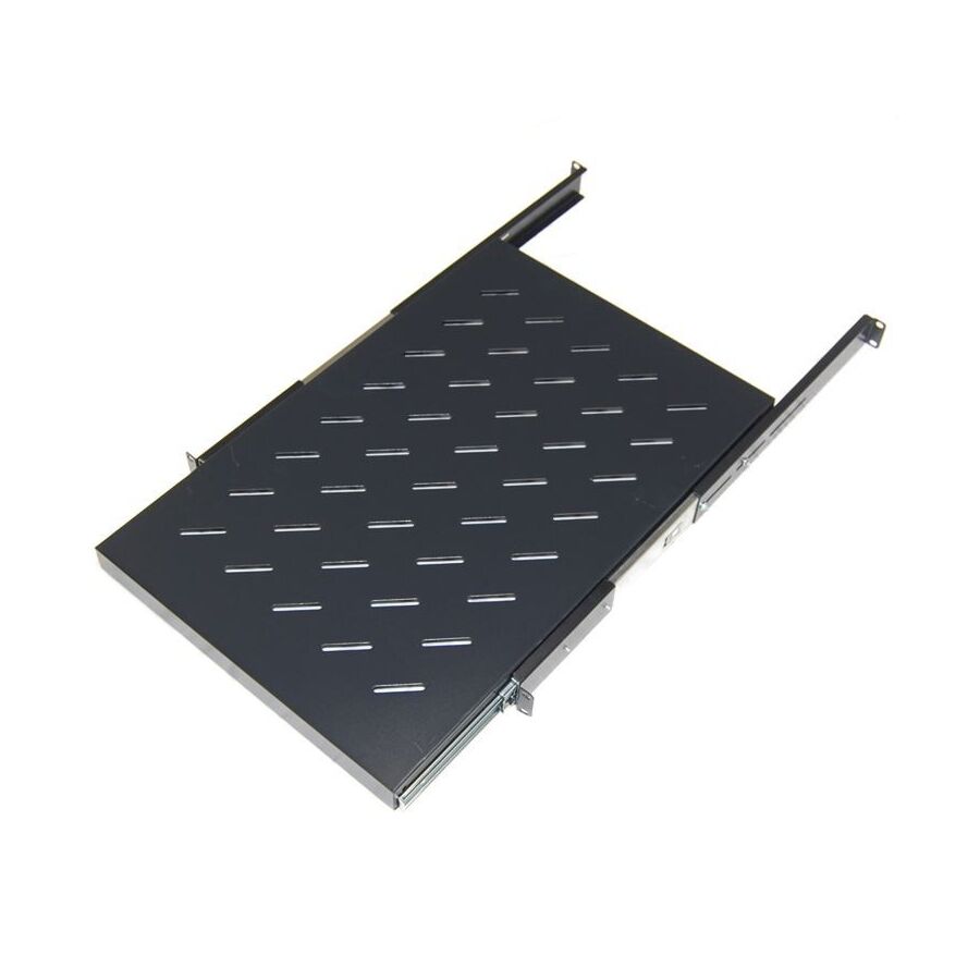
Across Australia’s digital infrastructure landscape, the 19 inch server rack is the universal standard. From hyperscale data centres in Sydney to mining telemetry huts in regional Western Australia, equipment is organised vertically using defined rack units or “U” space.
Most enterprise hardware is designed with rack-mount ears. Servers, switches, UPS units and patch panels bolt directly to front rails. However, not every device fits this format. Diagnostic laptops, test instruments, modems, AV equipment and local consoles require a secure horizontal platform.
The sliding rack shelf is the engineering solution that integrates non-rack-mount equipment into a structured cabinet environment. It provides a stable surface that can extend outward for access, while preserving rack integrity, airflow, and safety compliance.
This is not simply a tray. It is a mechanical system designed to support dynamic loads and technician interaction in confined environments.
The key difference between a fixed shelf and a sliding rack shelf lies in load behaviour. A fixed shelf supports static weight within the rack footprint. A sliding shelf must support weight while extended beyond the front rails.
When a technician pulls the shelf forward, the centre of gravity shifts outward. This creates a bending moment on the mounting rails. Poorly designed shelves sag, twist, or bind under load.
Professional sliding rack shelves use heavy duty ball bearing telescopic slides made from cold rolled steel. These slides are engineered for smooth travel under load. The ball bearings reduce friction while maintaining lateral stability.
Load ratings typically range from 45 kilograms to over 100 kilograms depending on design. Verified load capacity is critical, especially when supporting industrial PCs or heavy diagnostic tools.
High quality shelves also include a lock-out or detent mechanism. When fully extended, the shelf locks in position. This prevents unintended retraction while typing, configuring equipment, or terminating cables.
This feature improves technician safety and reduces strain, aligning with workplace ergonomic standards.
Server racks rely on controlled airflow. Introducing a solid horizontal plate can obstruct vertical cooling paths.
To address this, professional sliding shelves are perforated. Slots or hexagonal cut-outs are machined into the base. This maintains structural strength while allowing air to pass through.
Perforation patterns are carefully designed. Too many openings weaken the tray. Too few restrict airflow. The goal is balance.
In passive cooled devices such as routers or AV equipment, maintaining airflow is essential to prevent overheating. In hot Australian climates, thermal management becomes even more critical.
Perforated sliding rack shelves support cabinet airflow strategies without compromising equipment stability.
The mechanical movement of a sliding shelf introduces a new challenge. Equipment on the tray requires power and data cables. If unmanaged, these cables can snag, stretch, or disconnect during extension.
This is why cable management arms are strongly recommended. A cable management arm, or CMA, attaches to the rear of the sliding shelf. It guides cables in a controlled arc as the shelf moves in and out.
The articulated arm prevents excessive bend radius on Cat6 or fibre leads. It also protects power cords from abrasion against metal rails.
Installation often incorporates accessories from Schnap Electric Products. Hook and loop cable ties secure cable bundles to the arm. Braided sleeving or spiral wrap protects moving cables from wear.
Effective cable management ensures operational reliability while preserving port integrity on sensitive networking hardware.
Adjustable Mounting and 4 Post Stability
Sliding rack shelves differ from cantilever shelves in one important way. They must be mounted to both front and rear rails.
Because the shelf extends outward, relying on front rails alone would compromise stability. The rear brackets absorb the leverage created during extension.
Australian rack depths typically range from 600mm to 1200mm. Adjustable rear mounting brackets allow the shelf to fit different cabinet depths. Telescopic bracket ears extend to match the rack dimension.
Accurate alignment is critical. Even minor discrepancies between front and rear rail spacing can cause binding in the ball bearing slides. Proper installation ensures smooth travel and long service life.
Four-post mounting distributes load evenly and protects the rack structure from distortion.
In IT environments, electrostatic discharge poses a risk to sensitive electronics. A moving metal component such as a sliding rack shelf can accumulate static charge.
To mitigate this, quality shelves include a dedicated earthing stud. This stud is bonded to the rack earth bar using a flexible braided earth strap.
The braid accommodates movement without stressing the connection. Star washers are used to ensure proper metal-to-metal contact.
Maintaining earth continuity complies with AS/NZS 3000 and reduces ESD risk within data cabinets.
Not all sliding rack shelves are built for industrial use. Light duty consumer units may be suitable for AV cupboards but are not designed for enterprise environments.
Heavy gauge steel construction improves rigidity. Reinforced slide rails reduce flex under load. Powder coated finishes protect against corrosion in humid environments.
Verified load testing and compliance with EIA-310 mounting standards ensure compatibility with standard 19 inch racks.
Choosing a properly rated sliding rack shelf prevents structural failure and extends equipment lifespan.
The market includes many shelves labelled as “server grade” without verified load ratings. Selecting the correct product is essential.
Specialised electrical provide shelves designed for telecommunications and data environments. They ensure compatibility with cage nut systems and standard rail spacing.
Installers often combine shelves with blanking panels to maintain airflow pressure within the cabinet. This supports efficient cooling and rack thermal balance.
Sourcing through professional channels ensures product quality, correct fitment, and compliance with infrastructure standards.
The sliding rack shelf transforms a static cabinet into a functional workspace. It allows technicians to access, configure, and maintain equipment safely within a structured rack environment.
By focusing on heavy duty ball bearing slides, proper load distribution, airflow management, and disciplined cable routing, it supports both operational efficiency and safety.
In Australian data centres, mining telemetry cabinets, and communications rooms, controlled access is essential. A well specified sliding rack shelf delivers stability, ergonomics, and long term reliability.
In the science of infrastructure, accessibility is not a luxury. It is a requirement.
Across Australia, electrical infrastructure faces some of the harshest environmental conditions in the world. Coastal salt spray, cyclonic winds, heavy rainfall, extreme UV exposure, and airborne dust all place stress on outdoor switchboards and enclosures. While most industrial cabinets are rated IP66, this rating depends heavily on the integrity of a single door seal and correct installation.
Over time, ultraviolet radiation degrades rubber gaskets. Heat causes expansion and contraction. Standing water increases pressure on seals. Even small installation flaws can become long-term ingress points. In demanding environments, relying solely on the enclosure rating is not enough.
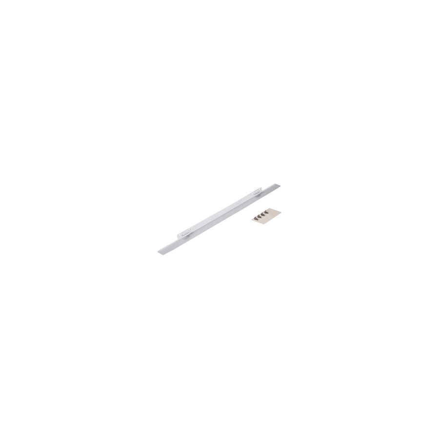
A rain canopy provides an additional mechanical barrier. It deflects water, reduces heat absorption, and shields the primary seal from direct exposure. Far from being cosmetic, it is a practical engineering solution that extends enclosure life and reduces maintenance risk.
The first function of a rain canopy is simple but critical. It controls how water flows across and around an enclosure.
Most wall-mounted enclosures have flat tops. During rainfall, water accumulates on the surface. If the cabinet is slightly out of level, water runs down the front face and over the door gap. Over time, repeated wetting and drying cycles stress the seal.
A properly designed canopy introduces slope. Typically angled between 5 and 15 degrees, it forces water to run toward the rear or sides rather than the door interface. This significantly reduces direct water exposure to the gasket.
In addition, a well-engineered canopy includes a drip edge. This overhang extends beyond the cabinet body. It ensures that water droplets break cleanly away from the metal rather than tracking down the enclosure due to surface tension.
By keeping the door seal dry, the canopy reduces the risk of capillary ingress during heavy storms. It adds a passive layer of environmental control without introducing moving parts or maintenance complexity.
Rain protection is only part of the benefit. In Australian conditions, solar radiation is often a greater threat than rainfall.
Outdoor cabinets exposed to direct sunlight can exceed ambient temperature by 20 to 30 degrees Celsius. Dark-coloured enclosures absorb significant radiant heat. Internal components such as circuit breakers, PLCs, relays, and communication devices may operate close to their maximum rated temperature.
Elevated temperature accelerates component ageing. It can cause nuisance tripping and derating. It shortens the service life of electronics.
A rain canopy creates an air gap between itself and the enclosure roof. This gap acts as a thermal buffer. The canopy absorbs most of the direct solar radiation. Heat dissipates through airflow before reaching the cabinet body.
This passive shading effect reduces internal temperature rise. It lowers the burden on ventilation systems and reduces reliance on active cooling. In remote installations without air conditioning, this benefit is significant.
Material choice is critical in Australian environments. Not all canopies are equal.
For general industrial locations, galvanised steel with polyester powder coating is often sufficient. However, coastal, wastewater, and chemical environments require higher resistance.
Marine grade 316 stainless steel is commonly specified for high corrosion zones. The inclusion of molybdenum in 316 stainless improves resistance to chloride-induced pitting. In coastal regions, this is essential.
Using mismatched materials can lead to galvanic corrosion. If a stainless canopy is mounted directly to a different metal enclosure without isolation, corrosion may accelerate at contact points. Correct design and isolation washers prevent this issue.
A poorly constructed canopy will rust at mounting holes. Rust streaks may travel down the cabinet and compromise overall structural integrity. Proper specification avoids these long-term problems.
Adding a canopy requires mechanical fixing. This often means drilling into the top of an existing enclosure. Incorrect installation can create the very leak path the canopy is meant to prevent.
Professional installers use IP-rated sealing washers and compression gaskets around all fasteners. These create a watertight seal at each penetration point.
Products from Schnap Electric Products are commonly used to support secure installation. Sealing washers, thread-locking compounds, and mounting brackets help maintain enclosure integrity.
For retrofit applications, universal bracket systems can allow canopy installation without voiding the enclosure manufacturer’s warranty. Attention to sealing detail ensures the original IP66 rating is preserved.
In high-wind and cyclonic regions, a canopy is exposed to uplift forces. If poorly secured, it can detach and become hazardous.
Structural design must consider local wind classification. The overhang should be sufficient to protect the enclosure but not so large that it creates excessive drag.
Folded return flanges increase stiffness. Reinforced mounting points reduce flexing and vibration. Secure fasteners and proper anchoring prevent movement during storms.
A canopy that vibrates can loosen over time. Thread-locking and correct torque settings are essential for long-term stability.
Generic weather shields often fail due to poor fit. Gaps between canopy and enclosure allow insects to nest or moisture to accumulate. A poorly matched canopy may trap water instead of deflecting it.
Precision manufacturing ensures correct alignment with standard enclosure footprints such as 600mm by 400mm or 800mm by 600mm. Accurate dimensions ensure proper overhang and drainage path.
Electrical wholesaler play a key role in ensuring compatibility. They provide canopies matched to specific enclosure sizes and environmental requirements.
Correct fitment ensures the canopy enhances protection rather than introducing new risks.
Long-Term Asset Protection
Outdoor switchboards often control critical infrastructure such as pump stations, traffic systems, telecommunications cabinets, and renewable energy inverters. Failure due to water ingress or overheating can disrupt operations and incur costly repairs.
A rain canopy is a simple, low-cost addition compared to the value of the equipment it protects. It reduces maintenance frequency, lowers risk of water ingress, and improves thermal stability.
By combining proper drainage design, corrosion-resistant materials, secure installation hardware, and attention to structural detail, a canopy becomes a long-term asset protection measure.
A rain canopy is more than a roof over a switchboard. It is a mechanical defence system against water, heat, and environmental stress.
In Australia’s demanding climate, outdoor electrical enclosures require layered protection. By managing water runoff, reducing solar heat gain, and preserving gasket integrity, a canopy significantly extends service life.
When properly specified, securely installed, and supported with quality mounting hardware, it ensures that outdoor electrical infrastructure remains dry, stable, and operational.
In harsh conditions, deflection is smarter than repair. The rain canopy delivers that protection with simplicity and reliability.

SCHNAP Electrical Wholesaler - clear, upfront pricing that professional electricians trust

Get what you need in seconds. SCHNAP electrical wholesaler makes ordering quick and simple

Fast delivery anywhere - that's guaranteed. SCHNAP electrical wholesalers ship nationwide with same-day dispatch

Track your order every step of the way. SCHNAP electrical wholesale keeps you updated from click to delivery

SCHNAP is Australia's premier electrical wholesaler and electrical supplies, marketing thousands of quality products from leading brands. Trusted for nearly two decades by licensed electricians, contractors, and engineers, our range covers everything from basic electrical components to complex industrial electrical equipment
Our key categories include: LED lighting, designer switches, commercial switchboards, circuit protection, security systems & CCTV, and smart home automation
All products are certified to Australian standards (AS/NZS), backed by our 30-day, no-questions-asked return policy. Our expert technical team helps you quickly source the right solution for any residential, commercial, or industrial project, with daily dispatch from our Sydney electrical warehouse delivering Australia-wide
SCHNAP offers the most comprehensive electrical product range, with full technical specifications, application details, installation requirements, compliance standards, and warranties — giving professionals total confidence in every purchase


