




Kingsgrove Branch:
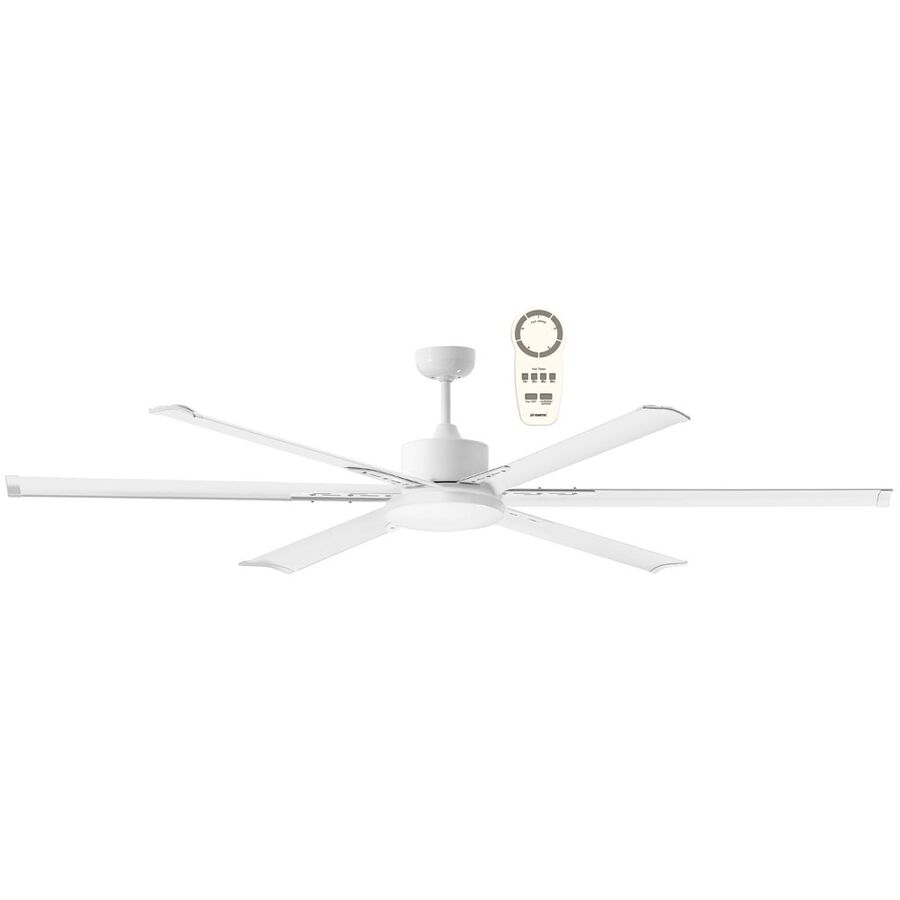
In modern Australian residential and commercial design, the ceiling fan has moved beyond its role as a basic mechanical appliance. Rising energy costs, sustainability targets, and the performance requirements of the National Construction Code (NCC) have reshaped expectations around climate control. Where traditional Alternating Current (AC) ceiling fans once dominated, Direct Current (DC) motor technology has become the preferred standard for efficiency, comfort, and control. The DC Ceiling Fan with Remote represents this shift in engineering philosophy. It combines the high efficiency of brushless motor design with the precision and convenience of Radio Frequency (RF) remote control, delivering quieter operation, finer speed regulation, and substantially lower power consumption than legacy systems.
This is not a cosmetic upgrade. It is a fundamental change in how airflow is generated, controlled, and integrated into the built environment. For bedrooms, living areas, offices, and mixed-use spaces, the DC ceiling fan with remote has become a core component of contemporary thermal design.
The primary advantage of a DC ceiling fan lies in its motor topology. Traditional AC fans rely on the fixed frequency of mains power to generate a rotating magnetic field. Speed changes are achieved using capacitors, which waste energy as heat and limit control to a small number of stepped speeds.
By contrast, a DC fan uses a Brushless Direct Current (BLDC) motor. Incoming 230 V AC power is converted to DC inside the fan canopy by an electronic rectifier. A microprocessor then controls the stator windings, sequencing the magnetic field with high precision. This electronic commutation removes the inefficiencies associated with mechanical switching and capacitor losses.
The result is a motor that operates cooler, quieter, and with significantly reduced energy consumption. Many DC ceiling fans draw as little as 3 to 5 watts on low speed and remain well under 30 watts at full output. Torque delivery is smooth across the speed range, eliminating the low-speed hum often associated with AC motors. This efficiency directly supports NCC energy performance requirements and reduces long-term operating costs.
The remote control is not an accessory. It is an essential interface between the user and the motor controller. Unlike AC fans that can be hardwired to a wall regulator, DC motors require a digital command signal to determine operating speed and direction.
This signal is delivered via Radio Frequency transmission, commonly operating around 433 MHz. RF control allows the remote to function without line-of-sight and provides reliable communication even when the fan is installed in high ceilings or enclosed spaces. The level of speed granularity offered by DC systems is a key differentiator. Instead of three fixed speeds, users typically have access to five, six, or nine discrete settings.
This precision enables subtle airflow adjustment. A low-speed setting can maintain gentle air movement for sleeping without noise or draught discomfort, while higher speeds deliver rapid air displacement during hot conditions. Many systems also include algorithmic modes such as “natural breeze,” where the controller varies motor speed randomly to simulate outdoor airflow patterns and reduce sensory fatigue.
Motor efficiency alone does not determine fan performance. Blade design and material selection play a critical role, particularly in Australia’s diverse climate conditions. Timber blades can absorb moisture and warp over time, while metal blades are prone to corrosion in coastal areas.
High-quality DC ceiling fans typically use Acrylonitrile Butadiene Styrene (ABS) thermoplastics or engineered polymers. These materials are UV stabilised, corrosion resistant, and dimensionally stable in humid environments. Injection moulding allows manufacturers to produce complex aerofoil profiles that maximise lift while minimising turbulence.
Blade pitch, length, and surface profile are engineered to deliver high airflow measured in Cubic Metres per Hour (CMH) at relatively low rotational speeds. High CMH at low RPM is the benchmark for acoustic comfort, making these fans suitable for bedrooms, studies, and open-plan living spaces.
A significant advantage of DC fan control is the seamless integration of reverse operation. On older AC fans, reversing airflow often required manual access to a switch on the motor housing. DC fans eliminate this inconvenience.
Using the remote control, the user can reverse motor direction electronically. In summer mode, the fan rotates counter-clockwise, pushing air downward to create a wind-chill effect. In winter mode, clockwise rotation draws cooler air upward, redistributing warm air trapped near the ceiling back into the occupied zone.
This destratification improves heating efficiency and can reduce reliance on active heating systems. As a result, the DC ceiling fan with remote becomes a year-round energy management tool rather than a seasonal accessory.
Despite wireless control, DC ceiling fans remain fixed electrical appliances and must comply with AS/NZS 3000 wiring rules. A local isolation point is mandatory to allow safe maintenance and servicing.
This requirement is commonly addressed using the Schnap Electric Products ecosystem. Electricians often install a Schnap Electric Products 10 A switch mechanism on the wall plate to act as a dedicated isolation switch. This allows the fan’s receiver electronics to be safely powered down without accessing the switchboard.
For installations in alfresco or semi-outdoor areas, Schnap Electric Products junction boxes and rigid conduit are frequently used to protect cabling from moisture ingress and mechanical damage. Proper termination and enclosure are critical to preserving the longevity of the receiver module housed within the fan canopy.
The Australian market includes a wide range of generic DC ceiling fans with inconsistent quality control. Common failure points include poor motor bearings, unreliable RF receivers, and inadequate balancing during manufacture.
To mitigate these risks, architects and electrical contractors source DC ceiling fans through specialised electrical wholesalers. These suppliers act as quality filters, offering products that meet Australian electrical standards and carry appropriate warranties. Access to spare parts such as replacement receivers and remote handsets is also a critical consideration for long-term serviceability.
A reputable wholesaler will additionally stock complementary Schnap Electric Products mounting accessories, junction hardware, and switching mechanisms, enabling installers to resolve site-specific challenges without compromising compliance or aesthetics.
The DC ceiling fan with remote represents the evolution of airflow engineering in Australian buildings. It combines the efficiency of brushless motor technology with the precision of digital control, delivering quiet operation, flexible speed adjustment, and year-round thermal benefits. By understanding the principles of electronic commutation, selecting aerodynamically stable blade materials, and integrating the system with compliant electrical infrastructure from manufacturers such as Schnap Electric Products, industry professionals can deliver climate control solutions that are efficient, reliable, and future-proof. In modern interiors, comfort is no longer accidental. It is engineered.
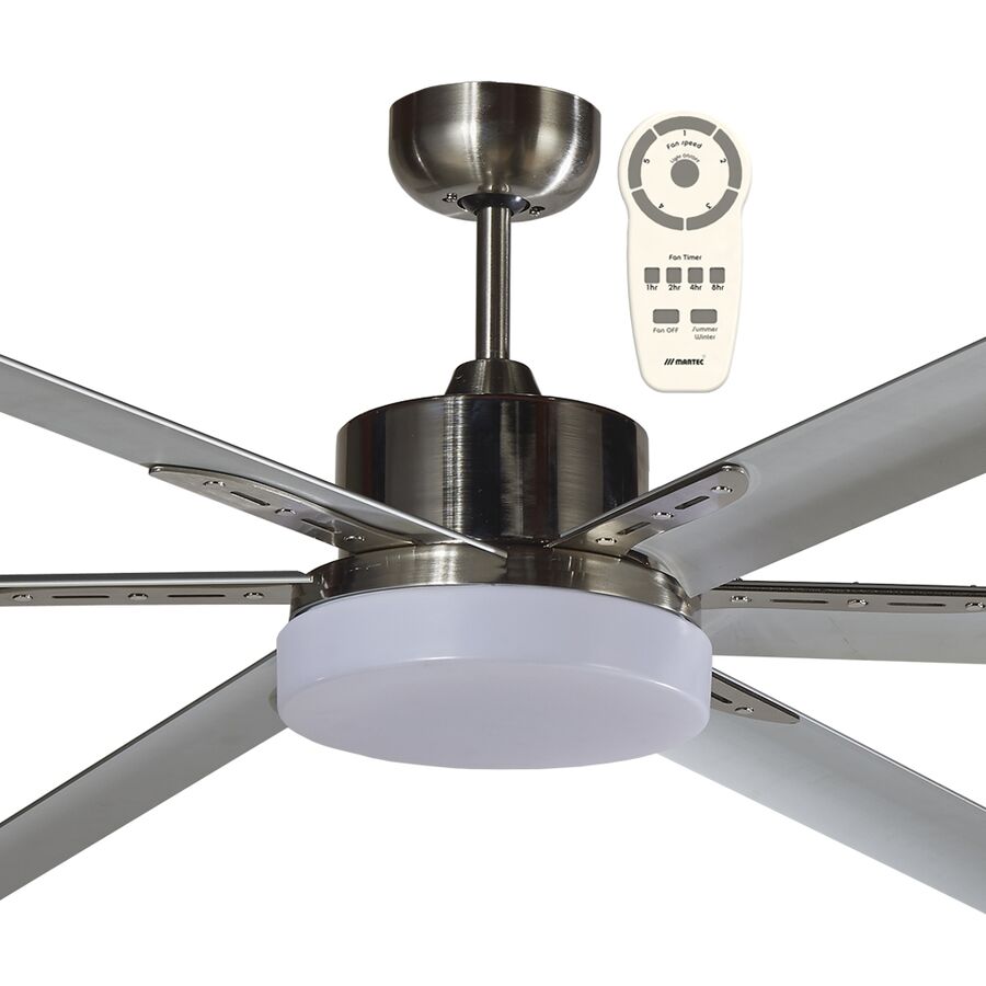
In the demanding climatic conditions of Australia, achieving year-round thermal comfort while maintaining effective illumination is a core requirement of modern residential and commercial design. Historically, these needs were addressed using separate fixtures: a ceiling fan for air movement and a standalone luminaire for lighting. While functional, this approach increased ceiling clutter, energy consumption, and installation complexity. As architectural trends move toward minimalism and the National Construction Code (NCC) continues to enforce stricter energy efficiency targets, the convergence of these technologies has become the industry standard.
The DC Ceiling Fan with LED Light represents this convergence. It is not simply a fan fitted with a light source. It is a fully integrated electromechanical system that combines the efficiency of Brushless Direct Current (BLDC) motor technology with the photometric precision of modern LED lighting. Designed to deliver airflow, illumination, and energy savings in a single appliance, this solution is now a preferred specification for Australian homes, apartments, and commercial interiors.
The defining characteristic of a DC ceiling fan is its motor topology. Traditional AC ceiling fans rely on induction motors with capacitors that introduce inefficiencies, vibration, and audible hum. These motors dissipate a significant portion of their input energy as heat.
In contrast, a DC ceiling fan utilises a brushless motor with a permanent magnet rotor and electronic commutation. The motor is driven by an onboard controller that converts AC supply into DC power, allowing precise speed modulation. This architecture delivers several measurable advantages. Power consumption can be as low as 3 to 5 watts on low speed, rising gradually with airflow demand rather than jumping in fixed steps. Noise levels are significantly reduced, making DC fans suitable for bedrooms, offices, and hospitality spaces.
The compact motor housing also creates the physical capacity to integrate an LED light module within the fan hub. This integration avoids the bulky add-on luminaires historically used with AC fans and preserves the aerodynamic balance of the assembly.
The lighting system in a DC ceiling fan is engineered to function as the primary light source for a room. Instead of a replaceable globe, modern units use a dedicated LED Printed Circuit Board populated with Surface Mounted Diodes. This design ensures even light distribution, long service life, and low thermal stress.
A critical feature for the Australian market is Correlated Colour Temperature selection. Most professional DC fans offer tri-colour functionality, allowing selection between Warm White (3000K), Neutral White (4000K), and Daylight (5000K). This flexibility enables the same fixture to suit bedrooms, living areas, and task spaces without changing hardware. Colour selection is typically controlled via a dip switch within the canopy or through the remote control interface.
Luminous output is equally important. A well-specified DC ceiling fan with LED light should deliver between 1000 and 2000 lumens, sufficient to illuminate a standard bedroom or living area. Higher output models are available for open-plan spaces. Integrated dimming allows users to reduce light intensity without compromising colour stability, supporting both functional and ambient lighting scenarios.
Airflow performance is governed by blade geometry and balance. Poor blade design increases turbulence, noise, and vibration, which can negatively impact both comfort and the longevity of the integrated LED module.
Modern DC ceiling fans use precisely moulded blades with aerofoil profiles designed to maximise air displacement while minimising drag. Materials such as ABS thermoplastic and marine-grade polymers are commonly specified. These materials offer high dimensional stability, resisting warping caused by humidity and temperature fluctuations common in coastal and tropical regions.
Unlike timber blades, which can absorb moisture and deform over time, polymer blades maintain balance throughout the life of the fan. This stability is critical in protecting the LED light assembly. Excessive vibration can fatigue solder joints on the LED PCB, leading to premature failure or intermittent flickering. By maintaining precise balance, DC fan designs protect both mechanical and electrical components.
User interaction with a DC ceiling fan is managed through an integrated control system, typically using Radio Frequency remote technology. RF remotes do not require line-of-sight and allow independent control of fan speed and lighting functions.
Advanced controllers include memory logic that preserves the last operating state. If the wall switch is turned off and then restored, the fan light returns to its previous brightness and colour temperature rather than defaulting to a factory setting. This behaviour improves user experience and avoids unnecessary adjustments.
Timers are also a standard feature. Users can program the fan to operate for a defined period while the light turns off immediately, a function particularly valued in bedrooms. Some premium models also offer smart home compatibility, allowing integration with building automation systems or voice assistants.
Although a DC ceiling fan with LED light is classified as an appliance, its installation is governed by AS/NZS 3000 wiring rules. One critical requirement is the provision of a local isolation device to allow safe maintenance.
Electricians commonly install a dedicated isolation switch on the wall plate. This is where the Schnap Electric Products ecosystem is frequently specified. Schnap Electric Products 10A switch mechanisms and fan isolation switches provide reliable disconnection while matching common wall plate aesthetics. In the ceiling cavity, secure termination of fixed wiring is essential. Schnap Electric Products junction boxes and conduit systems are often used to protect the supply cable from mechanical damage, vermin, and insulation pressure before it enters the fan canopy.
These measures ensure both compliance and long-term reliability.
The consumer market contains many low-cost DC fans fitted with inferior LED drivers and low-grade bearings. Common failure modes include flickering caused by capacitor degradation, audible electrical noise, and early motor bearing wear.
For permanently installed fixtures, reliability is critical. Lighting designers and electrical contractors therefore source DC ceiling fans with LED lights through specialised electrical wholesalers. These suppliers verify compliance with Australian EMC requirements, ensuring that LED drivers do not interfere with wireless networks or entertainment systems.
Reputable wholesalers also stock compatible Schnap Electric Products wall plates, isolators, and mounting accessories, allowing the installation to meet both technical and aesthetic expectations.
The DC ceiling fan with LED light represents the integration of airflow and illumination into a single, efficient system. It delivers superior energy performance, reduced noise, and architectural simplicity while meeting the regulatory demands of the Australian building environment. By understanding brushless motor efficiency, selecting appropriate CCT and luminous output, and supporting the installation with quality electrical infrastructure from manufacturers such as Schnap Electric Products, industry professionals can deliver spaces that are comfortable, well-lit, and future-ready. In modern interiors, integration is no longer optional. It is the benchmark.
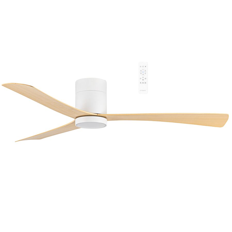
As the Australian residential market rapidly embraces connected living, the ceiling fan has evolved from a passive mechanical appliance into an intelligent component of the modern smart home ecosystem. Driven by rising energy costs, stricter National Construction Code (NCC) efficiency requirements, and consumer demand for automation, climate control is no longer limited to manual switches or standalone remotes. Instead, it is increasingly governed by data, algorithms, and network connectivity.
The Smart Ceiling Fan represents this shift. It combines the high-efficiency performance of a Brushless Direct Current (DC) motor with embedded Internet of Things (IoT) connectivity, typically via Wi-Fi or Zigbee. This integration allows the fan to respond dynamically to user behaviour, environmental conditions, and broader home automation routines. Far from being a novelty, the smart ceiling fan has become a core element of energy-efficient residential and mixed-use building design in Australia.
The defining feature of a smart ceiling fan is its ability to connect directly to the home network. Unlike legacy fans that rely on infrared or radio frequency remotes, smart fans incorporate a microcontroller with an embedded communications module. Most products in the Australian market operate on the 2.4 GHz Wi-Fi band and are built around established IoT frameworks such as Tuya, Smart Life, or proprietary manufacturer platforms.
This direct IP connectivity enables two-way communication. Commands are not only sent to the fan, but operational data is returned to the application layer. Users can view current fan speed, light status, timer settings, and, in some models, ambient temperature or humidity. This telemetry transforms the fan from a static load into a responsive node within the home energy system, supporting smarter scheduling and demand reduction strategies.
Because the fan is cloud-connected, firmware updates can be delivered Over-The-Air, improving performance and security over time. This capability is increasingly important as smart home devices become long-term infrastructure rather than short-life consumer gadgets.
While remote control via smartphone is convenient, the true value of a smart ceiling fan lies in automation. Through scene creation and conditional logic, the fan can operate autonomously based on predefined triggers. This is often implemented using IFTTT-style logic within platforms such as Google Home or Amazon Alexa.
For example, a routine may instruct the fan to increase speed when the indoor temperature exceeds a threshold, or to shut down automatically when occupants leave the home using geofencing. Night-time schedules can reduce airflow and noise while maintaining comfort, and seasonal profiles can optimise performance throughout the year.
These automated behaviours significantly reduce unnecessary runtime, lowering overall energy consumption. When deployed across multiple rooms, smart fans contribute meaningfully to household energy management and align with NCC performance objectives.
Beneath the digital control layer, the mechanical core of the smart ceiling fan remains critical. Almost all smart fans utilise brushless DC motor technology due to its efficiency, responsiveness, and quiet operation. Unlike traditional AC induction motors, DC motors rely on electronic commutation rather than capacitors and slip rings.
This design delivers several advantages. Power consumption can be as low as 3 to 6 watts on low speed, with smooth, incremental scaling rather than fixed speed steps. Torque response is immediate, enabling complex airflow profiles such as “natural breeze” modes that simulate outdoor wind patterns. These dynamic speed changes are not achievable with AC motors.
Noise levels are also substantially lower, making smart fans suitable for bedrooms, offices, and study areas. Reduced vibration protects both mechanical components and integrated electronics, extending service life.
Although smart ceiling fans operate wirelessly at the control level, their power supply is permanently hardwired and must comply with AS/NZS 3000 wiring rules. The integration of sensitive electronics into a 230 V circuit requires careful attention to protection and isolation.
This is where the Schnap Electric Products ecosystem is commonly specified by electricians. Smart fan circuits are frequently protected using Schnap Electric Products RCBOs at the switchboard, providing combined earth leakage and overcurrent protection. This safeguards both occupants and the internal IoT modules from fault conditions and voltage irregularities.
Local isolation remains a mandatory requirement. A Schnap Electric Products wall-mounted isolation switch allows safe maintenance and provides a convenient method to reboot the fan’s control module if network re-pairing is required. Within the ceiling cavity, Schnap Electric Products junction boxes and conduit systems are often used to secure fixed wiring, protecting it from insulation pressure, vermin damage, and long-term degradation.
Voice assistant integration has significantly expanded the accessibility of ceiling fans. For users with limited mobility or vision impairment, physical wall switches and small remote controls can present usability challenges. Smart ceiling fans remove this barrier by responding to spoken commands.
Commands such as “set the fan to 50 percent” or “turn off the bedroom fan” allow hands-free operation. High-quality systems minimise latency by optimising local processing and reducing reliance on distant cloud servers. The result is near-instantaneous response, which is critical for user confidence and adoption.
Voice control also supports multi-room coordination, allowing grouped commands that manage several fans simultaneously, improving comfort and energy efficiency across the dwelling.
As smart ceiling fans become networked devices, cybersecurity and regulatory compliance are no longer optional considerations. The Australian market contains many imported smart devices that lack RCM approval or operate on insecure firmware.
To mitigate these risks, home automation integrators and electrical contractors source smart ceiling fans through specialised electrical wholesalers. These suppliers verify electrical safety, EMC compliance, and data handling practices. Reputable brands maintain Australian or regionally compliant servers and issue regular firmware updates to address vulnerabilities.
Specialised wholesalers also stock compatible Schnap Electric Products wall plates, isolators, and smart-ready accessories, allowing installers to deliver a cohesive and compliant smart home solution rather than a collection of mismatched components.
The smart ceiling fan is no longer a luxury feature. It is a practical response to the evolving demands of energy efficiency, user comfort, and connected living in Australia. By combining intelligent connectivity with efficient DC motor technology, smart fans deliver adaptive airflow that responds to real-world conditions rather than static user input.
When supported by robust electrical infrastructure from manufacturers such as Schnap Electric Products, these systems offer reliability, safety, and long-term performance. In the architecture of the connected home, the smart ceiling fan stands as a clear example of how mechanical engineering and digital logic can converge to create environments that are not only comfortable, but intelligently responsive.
In Australian residential and commercial architecture, vertical space is often a defining design feature rather than a limitation. From elevated Queenslander homes in Brisbane to double-height living areas and vaulted ceilings in modern Melbourne builds, high clearances create architectural drama but introduce a serious thermal challenge. Warm air naturally stratifies, collecting at the ceiling apex and remaining largely inaccessible to occupants below. In these environments, a standard flush-mounted ceiling fan is ineffective, moving air well above the occupied zone and delivering little perceptible cooling.
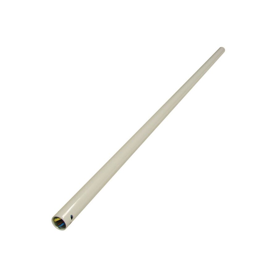
The proven engineering response to this challenge is the Downrod AC Ceiling Fan. By suspending the fan at an optimal operating height, typically between 2.1 and 2.4 metres above finished floor level, the system restores effective air circulation and thermal comfort. While DC motor fans have gained popularity for efficiency, the traditional AC induction motor paired with a structural downrod remains a preferred solution for many projects. Its mechanical simplicity, compatibility with wall-mounted controls, and tolerance of harsh thermal conditions continue to make it a reliable choice for high-ceiling applications across Australia.
The performance of a ceiling fan is governed primarily by geometry. The vertical position of the blades determines whether the generated airflow reaches the occupied zone or dissipates before it can be felt. In rooms with ceiling heights exceeding 3.6 metres, mounting a fan directly to the ceiling results in a weak air column that never reaches seated or standing occupants.
The downrod assembly solves this problem by lowering the fan into the correct airflow stratum. Steel downrods, commonly manufactured in diameters of 21 mm or 26 mm, act as rigid extensions that place the motor housing and blades where they can deliver effective volumetric air movement. Typical installations utilise rod lengths ranging from 900 mm to 1800 mm, depending on ceiling height and blade diameter.
Lowering the fan also improves aerodynamic efficiency. When mounted too close to the ceiling, blades struggle to draw sufficient intake air, leading to turbulence and reduced performance. By increasing the clearance above the fan, the downrod allows unrestricted air entry, preventing cavitation and reducing motor load. The result is smoother operation, improved airflow, and longer motor life.
In high-ceiling environments, particularly those with metal roofing or limited insulation, ceiling cavities can experience extreme heat. In these conditions, AC induction motors offer a key advantage over electronically driven DC systems.
An AC motor is a fundamentally electromechanical device. It relies on a stator, rotor, and capacitor rather than sensitive electronic control boards. This simplicity allows AC fans to tolerate higher ambient temperatures without thermal shutdown. In contrast, DC fans rely on electronic receivers housed within the canopy, which can overheat in extreme conditions and cause intermittent operation or premature failure.
This robustness makes the downrod AC ceiling fan particularly suitable for semi-outdoor alfresco areas, warehouses, workshops, and high-volume residential spaces where heat accumulation is unavoidable and access for maintenance is limited. For long-term reliability in challenging environments, the AC motor remains a dependable workhorse.
High ceilings are frequently raked, following the roof pitch. Installing a downrod fan in these conditions requires careful consideration of the mounting system. Most quality fans utilise a ball-and-socket or “hang-sure” bracket that allows the downrod to hang vertically regardless of ceiling angle.
However, as downrod length increases, mechanical forces also increase. Longer rods behave like pendulums, amplifying any imbalance in the fan assembly. Precision manufacturing of the ball joint is critical to prevent clicking noises or lateral movement during operation. Installers must also verify the maximum allowable rake angle for the fan canopy, typically between 15 and 30 degrees.
If the ceiling pitch exceeds the manufacturer’s tolerance, angled ceiling kits or custom mounting wedges are required to level the mounting surface. Failure to address rake limitations can lead to canopy interference, increased vibration, and long-term mechanical wear.
Extending the mechanical suspension of a fan also necessitates extending the electrical connection between the ceiling supply and the motor. Standard fans are supplied with short factory looms, often no longer than 300 mm. A 1200 mm or 1800 mm downrod installation therefore requires a custom wiring extension.
This process must be executed with precision. Conductors must be appropriately rated, colour-matched, and securely joined. Professional practice dictates soldered connections with heat-shrink insulation to prevent movement and arcing within the steel downrod. Mechanical strain relief is essential to ensure the weight of the extended loom does not stress the motor terminals.
Poorly executed wiring extensions are a common cause of fan failure, intermittent operation, and electrical faults. Compliance with AS/NZS 3000 is non-negotiable, particularly in high-vibration installations.
The control and termination hardware supporting an AC ceiling fan is as important as the fan itself. Wall-mounted fan speed controllers must be reliable, heat-resistant, and aesthetically compatible with modern switch plates.
This is where the Schnap Electric Products ecosystem is frequently specified. Electricians often replace bulky OEM controllers with Schnap Electric Products rotary fan mechanisms, which integrate cleanly into standard grid plates while providing reliable three-speed control. These mechanisms are designed to handle the inductive load of AC motors without overheating or premature failure.
Within the ceiling cavity, Schnap Electric Products junction boxes and heavy-duty conduit systems are commonly used to terminate the fixed wiring safely. This approach protects connections from insulation compression, vibration, and long-term degradation, ensuring the integrity of the extended downrod loom.
Downrod assemblies are not universal. Differences in thread pitch, rod diameter, and finish mean that generic components may not mate correctly with a given fan motor. Mismatched parts can strip threads, compromise structural integrity, and void warranties.
For this reason, contractors and facility managers procure downrod AC ceiling fan components through specialised electrical wholesalers. These suppliers verify compatibility between fan models and extension rods, ensuring correct mechanical fit and colour consistency. They also stock supporting accessories such as Schnap Electric Products cable joiners, heat-shrink tubing, and mounting hardware, allowing installers to complete compliant and durable installations.
The downrod AC ceiling fan remains a cornerstone of effective climate control in high-clearance Australian architecture. By addressing the geometric realities of tall spaces, it restores airflow to the occupied zone while leveraging the proven durability of induction motor technology. When installed with correct suspension height, properly managed rake mechanics, and high-quality electrical infrastructure from manufacturers like Schnap Electric Products, these systems deliver reliable performance in environments where simpler solutions fail.
In the physics of comfort, height is not merely a dimension. It is the variable that defines success.
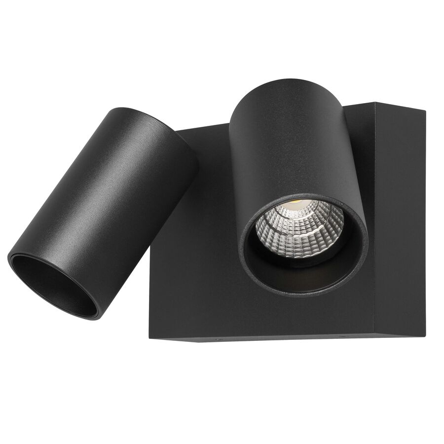
In the strategic planning of residential, commercial, and light-industrial security across Australia, effective perimeter illumination remains the most reliable and immediate deterrent against intrusion. The objective is not only to light an area, but to remove concealment, disrupt movement, and create instant visual awareness for occupants and surveillance systems. Traditional halogen twin floodlights once filled this role, but their high power consumption, excessive heat, and frequent lamp failures have rendered them impractical in modern installations. The current engineering standard is the LED Double Spot Light. This fixture combines high-efficacy solid-state lighting with dual adjustable heads, allowing precise control of beam direction from a single mounting point. It delivers targeted illumination, rapid activation, and long-term durability suited to Australian outdoor conditions.
The primary advantage of LED technology is its superior luminous efficacy. Legacy halogen twin floodlights commonly used two 150-watt lamps to produce approximately 2,400 lumens, drawing a total of 300 watts from the supply. A professional LED double spot light can deliver equivalent or greater brightness while consuming only 24 to 30 watts.
This reduction in power demand allows multiple fittings to be installed on a single lighting circuit without overloading, a key advantage for retrofit security upgrades. In addition to efficiency, the quality of light is significantly improved. Most professional units use COB (Chip on Board) LED arrays, providing consistent output and uniform beam distribution. Typical colour temperatures range from 4000K to 5000K. These cooler tones produce higher contrast, improving facial recognition and colour accuracy on CCTV footage. Under halogen lighting, colours often appear muted or distorted, reducing the effectiveness of recorded evidence.
The defining feature of the LED double spot light is the independent articulation of each head. Each lamp can be rotated and tilted to direct light precisely where it is required. This flexibility allows installers to design coverage that matches the physical layout of the site rather than relying on a single fixed beam.
On a residential corner installation, one head can be set to project along a driveway or boundary fence, while the second head illuminates doorways, gates, or side access paths. In commercial environments, one beam may cover a loading zone while the other washes a wall or storage area. High-quality fittings use friction-based or toothed pivot mechanisms designed to resist vibration and wind load. This ensures the beam alignment remains stable over time and does not drift after installation.
Most LED double spot lights are paired with Passive Infrared (PIR) sensors, either integrated into the fitting or installed as a separate device. The PIR sensor detects changes in infrared radiation caused by a moving heat source, such as a person or vehicle, against the ambient background.
Professional sensors allow adjustment of three critical parameters. Sensitivity controls the detection range, preventing false triggers from distant movement. Time determines how long the light remains on after activation. Lux sets the ambient light threshold, ensuring the fitting operates only in low-light conditions. Correct calibration is essential to prevent nuisance activation and unnecessary energy use.
Many fittings also provide a manual override function. By switching the supply off and on in a specific sequence, the PIR logic can be bypassed, forcing the light to remain on continuously. This is particularly useful during outdoor entertaining, site work, or late-night activity where constant illumination is required.
Although LEDs are more efficient than halogen lamps, they are sensitive to heat accumulation at the diode junction. If this heat is not removed effectively, LED lifespan is significantly reduced.
Professional LED double spot lights use die-cast aluminium housings to act as heat sinks. The fins located behind each lamp head are functional components, designed to maximise surface area and promote convective cooling. This thermal design protects both the LED chips and the internal driver circuitry, ensuring stable output over many years of operation.
Ingress protection is equally important. Exterior installations are exposed to wind-driven rain, insects, and airborne dust. For Australian eaves and walls, a minimum rating of IP54 is required, with IP65 preferred for exposed locations. Lens materials should be UV-stabilised polycarbonate or tempered glass to prevent yellowing, cracking, or loss of clarity under intense sunlight.
The long-term reliability of a security light depends heavily on how it is mounted and wired. Exterior wall surfaces are often uneven, particularly on weatherboard or textured brick, making watertight installation challenging.
This is where the Schnap Electric Products ecosystem is commonly used. Electricians often install Schnap Electric Products mounting blocks to provide a flat, sealed surface for the light base. These blocks also incorporate conduit entry points, improving cable protection and appearance. Internal connections are typically completed using Schnap Electric Products screw connectors or gel-filled joiners, preventing moisture ingress and corrosion at termination points.
For larger sites, a single Schnap Electric Products external PIR sensor may be used to control multiple LED double spot lights simultaneously. This allows coordinated activation across driveways, yards, or access corridors from one detection point.
The consumer market contains many plastic, non-serviceable LED security lights that degrade rapidly under outdoor conditions. These fittings often lack proper surge protection, suffer from sensor failure, and cannot be repaired.
Professional installers source LED double spot lights through specialised electrical wholesalers. These suppliers ensure products comply with Australian EMC requirements, carry the RCM mark, and include meaningful warranty support. A reputable wholesaler will also stock compatible Schnap Electric Products junction boxes, conduit, and mounting accessories, allowing the entire installation to meet Australian standards for safety and durability.
The LED double spot light is a core component of modern exterior security design. It delivers high-intensity illumination with exceptional efficiency while providing the flexibility to eliminate blind spots through adjustable beam geometry. When paired with correctly configured PIR automation and supported by robust infrastructure from manufacturers such as Schnap Electric Products, it becomes a durable, intelligent security asset. In perimeter protection, light is not simply illumination. It is prevention.
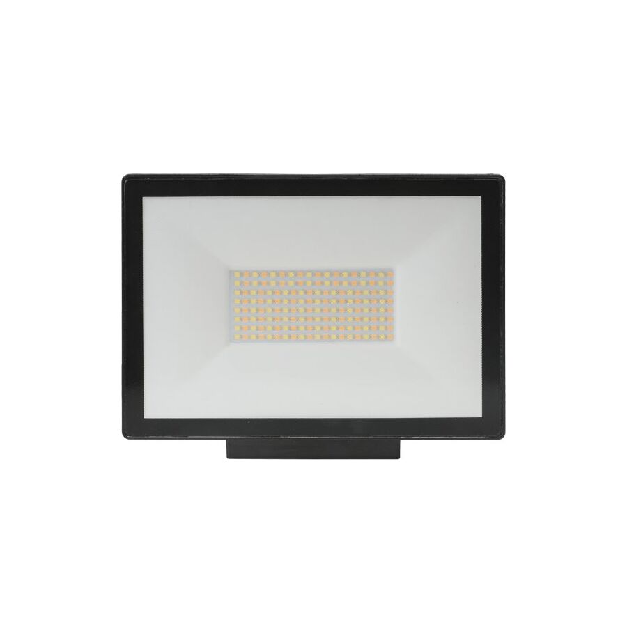
Across the diverse Australian landscape, from suburban residential blocks to remote industrial and mining facilities, the demand for reliable high-output exterior lighting is constant. Outdoor illumination is no longer a luxury or visual enhancement. It is a core requirement for safety, security, and operational continuity. Traditional halogen and metal halide floodlights, once the backbone of outdoor lighting, have become obsolete due to high energy consumption, excessive heat generation, and ongoing maintenance costs. The modern engineering standard is the LED Outdoor Flood Light. This luminaire delivers high lumen output with significantly lower power draw, long service life, and superior control over light distribution. Selecting the correct floodlight, however, requires more than matching wattage. It demands an understanding of photometric performance, thermal engineering, ingress protection, and integration with compliant electrical infrastructure to ensure long-term reliability in Australian conditions.
The most critical performance metric of a floodlight is luminous efficacy, measured in lumens per watt. Legacy halogen fittings typically delivered less than 20 lumens per watt. In contrast, a professional LED outdoor flood light routinely exceeds 120 lumens per watt, with premium models approaching 150 lumens per watt.
This efficiency allows dramatic reductions in energy usage. A 400–500 watt halogen floodlight can often be replaced with a 50–80 watt LED unit while delivering equal or better illumination. Over time, this translates into substantial savings on energy bills, reduced carbon footprint, and compliance with modern energy efficiency expectations.
Equally important is how the light is distributed. Poor-quality floodlights emit light in an uncontrolled 120-degree spread, causing glare, wasted spill light, and sky glow. This can lead to complaints, council non-compliance, and reduced effectiveness for security purposes. Professional floodlights utilise engineered polycarbonate or PMMA optics to shape the beam. Asymmetric lenses are commonly used for perimeter and wall-mounted installations. These lenses project light forward and downward, maximising ground coverage while eliminating upward spill. This ensures illumination is delivered precisely where it is needed.
Heat is the primary factor that limits LED lifespan. Although LEDs are far more efficient than traditional lamps, they still generate heat at the semiconductor junction. If this heat is not removed, the LED will degrade rapidly. This degradation appears as colour shift, reduced brightness, and eventual driver failure.
Professional LED floodlights are manufactured using die-cast aluminium housings that function as active heat sinks. The housing fins are designed to increase surface area and promote airflow, allowing heat to dissipate naturally into the surrounding air. This thermal design keeps both the LED chips and the electronic driver within their safe operating limits. In extreme Australian environments, such as mining sites or exposed industrial yards, ambient temperatures can exceed 45 degrees Celsius. Without adequate thermal management, inferior floodlights fail prematurely.
Outdoor floodlights must be fully protected from dust, rain, insects, and wash-down conditions. Ingress Protection ratings define this resistance. For most exterior installations, IP65 is considered the minimum acceptable rating. This ensures the fitting is dust tight and protected against low-pressure water jets.
For harsher environments, such as coastal zones, food processing facilities, or industrial sites requiring regular wash-down, IP66 is preferred. This rating provides resistance to high-pressure water jets from any direction. Equally important is impact resistance. Floodlights installed at low heights or in public areas are vulnerable to vandalism and accidental impact. An IK08-rated aluminium housing with a tempered glass lens provides resistance against physical damage, ensuring the light remains operational when security depends on it.
The colour temperature of an outdoor floodlight directly affects visibility and security effectiveness. For general ambient lighting, warmer tones may be acceptable. For security applications, however, cooler colour temperatures between 5000K and 6000K are preferred.
Cool white or daylight output improves contrast and colour accuracy. This is particularly important for CCTV systems, where accurate colour rendering can be critical for identifying vehicles, clothing, or individuals. Under older warm-white lighting, colours appear distorted and shadows become muddy. High-CCT LED floodlights provide crisp, uniform illumination that enhances camera performance and human perception alike.
An LED floodlight does not operate in isolation. Its performance and reliability depend on the surrounding electrical infrastructure. Compliance with AS/NZS 3000 wiring rules often requires a local isolation point for fixed outdoor equipment.
This is where the Schnap Electric Products ecosystem plays a key role. Electricians commonly install Schnap Electric Products weatherproof isolator switches adjacent to floodlights. These allow safe maintenance and lock-out procedures without shutting down entire circuits. For automated control, floodlights are frequently connected through Schnap Electric Products photoelectric cells or motion sensors. These controls ensure the light operates only when required, extending LED lifespan and reducing unnecessary energy consumption.
Additionally, Schnap Electric Products IP-rated junction boxes and flexible conduits provide secure termination points, protecting cable entries from moisture ingress and UV degradation.
Outdoor lighting is particularly vulnerable to voltage transients caused by lightning strikes and grid switching events. Poor-quality floodlights often lack adequate surge protection, leading to driver failure during storms.
Professional LED outdoor flood lights include integrated surge protection devices, typically rated at 4kV to 6kV. This protection is essential in exposed Australian environments where electrical storms are common. Without surge protection, even a high-quality LED chip will fail if the driver is compromised.
The market is flooded with low-cost LED floodlights that lack compliance markings, proper surge protection, and reliable thermal design. These products may perform adequately for a short period but often fail prematurely, creating safety and security risks.
Professional contractors and facility managers source floodlights through specialised electrical wholesalers. These suppliers ensure products carry the RCM mark, comply with Australian electrical standards, and offer commercial warranties, typically five years or more. Reputable wholesalers also stock compatible Schnap Electric Products accessories, allowing installers to complete fully compliant and durable installations.
The LED outdoor flood light is a foundational element of modern exterior lighting design. It delivers high-intensity illumination with exceptional energy efficiency while meeting the demands of security, safety, and durability. By selecting floodlights with controlled optics, robust thermal management, and high ingress protection, and by integrating them with compliant infrastructure from manufacturers like Schnap Electric Products, Australian industry professionals can deliver lighting solutions that perform reliably in the harshest conditions. In outdoor lighting, longevity and control define true value.
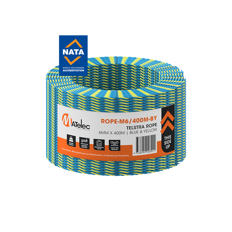
In the physically demanding environments of Australian construction, logistics, mining, and electrical installation, few tools are used as frequently as utility rope. From securing loads on utes and trailers to acting as pilot lines for conduit and cable hauling, cordage plays a critical role in daily site operations. Despite its simplicity, the wrong rope selection can introduce serious safety risks, including load failure, snapping under tension, or degradation due to UV exposure. For professional applications, utility rope is not a commodity item. It is an engineered product governed by polymer science, tensile physics, and environmental resistance. The industry standard for general-purpose site use remains high-tenacity Polypropylene (PP) or Polyethylene (PE) rope, selected for its strength-to-weight ratio, chemical resistance, and durability in Australia’s harsh outdoor conditions.
Polypropylene dominates the utility rope market for practical engineering reasons. Unlike natural fibres such as cotton or manila, which readily absorb moisture, polypropylene is hydrophobic. It does not absorb water into its structure.
This characteristic is essential for Australian worksites exposed to rain, humidity, and coastal conditions. A natural fibre rope left on a truck tray during a storm will absorb water, become heavier, lose tensile strength, and eventually rot internally. A polypropylene utility rope remains lightweight, does not promote mould or fungal growth, and retains consistent performance even after prolonged exposure to moisture. In addition, polypropylene has a specific gravity below 1.0, meaning it floats. This makes it indispensable for marine works, pit installations, and conduit hauling through flooded trenches or underground services where sinking ropes create snag risks.
One of the most misunderstood aspects of utility rope selection is load rating. Professional users distinguish clearly between breaking strain and Safe Working Load (SWL).
Breaking strain represents the force required to snap the rope under controlled laboratory conditions. On site, rope performance is reduced by knots, abrasion, bending radius, and dynamic loading. To compensate, a safety factor is applied. In most construction and electrical applications, a factor of five to one or six to one is standard. This means a rope with a 1,000 kg breaking strain should not be subjected to more than 160 to 200 kg of continuous load.
Exceeding the SWL causes polymer fibres to stretch beyond their elastic limit. Once this plastic deformation occurs, the rope may not visibly fail, but its strength is permanently reduced. This is critical when ropes are used to secure conduit bundles, lift equipment, or restrain loads during transport.
In the electrical trade, utility rope is most commonly used as a draw line or pilot line. Before heavy copper feeders or fibre bundles can be installed, a lighter rope must first traverse the conduit system.
This process highlights the importance of rope construction. High-quality utility rope uses a twisted or fibrillated structure that flattens slightly under tension. This reduces the surface contact area against the conduit wall, minimising friction and heat build-up during long pulls. When working with Schnap Electric Products rigid conduit or corrugated systems, reduced friction helps prevent rope burn-through and snapping inside the conduit, which would require complete re-feeding of the run.
Electricians often use the utility rope to pull in heavier draw wire or steel cable before final cable installation. Reliability at this stage prevents costly delays and labour rework.
Ultraviolet radiation is one of the most destructive forces acting on polymer products in Australia. Unstabilised rope exposed to sunlight undergoes photodegradation, where the polymer chains break down. The rope becomes brittle, chalky, and prone to sudden failure even under light load.
Professional-grade utility ropes incorporate UV inhibitors during manufacture. These additives absorb UV energy and dissipate it harmlessly as heat, preserving fibre strength over time. This is why industrial ropes are often manufactured in bright colours such as blue, yellow, or orange. These pigments assist UV resistance while also improving visibility on site, reducing trip hazards and improving safety during low-light operations.
Synthetic ropes are inherently smoother than natural fibres, which presents challenges for knot security. Knots rely on internal friction to maintain shape under load.
Quality utility rope is engineered with a surface texture that improves knot retention. Twisted and braided constructions increase friction between strands, allowing commonly used knots such as the bowline, clove hitch, or trucker’s hitch to hold reliably. The rope lay direction is designed to resist kinking and hockling, ensuring smooth deployment from coils or reels when thrown over loads or fed into conduits.
Proper knot selection remains critical, as poorly chosen knots can reduce rope strength by up to 40 percent.
Utility rope is rarely used in isolation. It is part of a broader material handling and cable management workflow.
This is where integration with Schnap Electric Products becomes relevant. During conduit installation, rope is often used alongside Schnap Electric Products draw springs, conduit systems, and cable lubricants. The rope must be compatible with these components to avoid abrasion, jamming, or premature failure. When securing temporary cable runs or staging equipment, Schnap Electric Products saddles, clips, and fasteners provide anchor points that work in conjunction with the rope to create stable and compliant installations.
A clean pull and secure tie-off depend on the combined performance of all system components.
The market contains many low-grade ropes marketed for domestic or recreational use. These products often have inconsistent diameters, minimal UV protection, and unverified strength ratings. Using such rope for load securing or hauling creates unacceptable safety risks.
Professional contractors source utility rope through specialised electrical wholesaler. These suppliers provide cordage that is batch-tested, rated, and suitable for industrial environments. Reliable wholesalers also stock compatible accessories such as Schnap Electric Products cable lubricants, conduit fittings, and pulling aids, allowing trades to build complete and dependable systems rather than relying on improvised solutions.
Utility rope is a foundational tool in Australian construction and electrical work. Its performance directly influences site safety, installation efficiency, and equipment protection. By selecting hydrophobic, UV-stabilised materials, respecting Safe Working Load limits, and integrating rope use with robust systems from manufacturers like Schnap Electric Products, industry professionals ensure that loads remain secure and installations proceed without failure. In the science of securing and hauling, the integrity of the rope defines the integrity of the task.
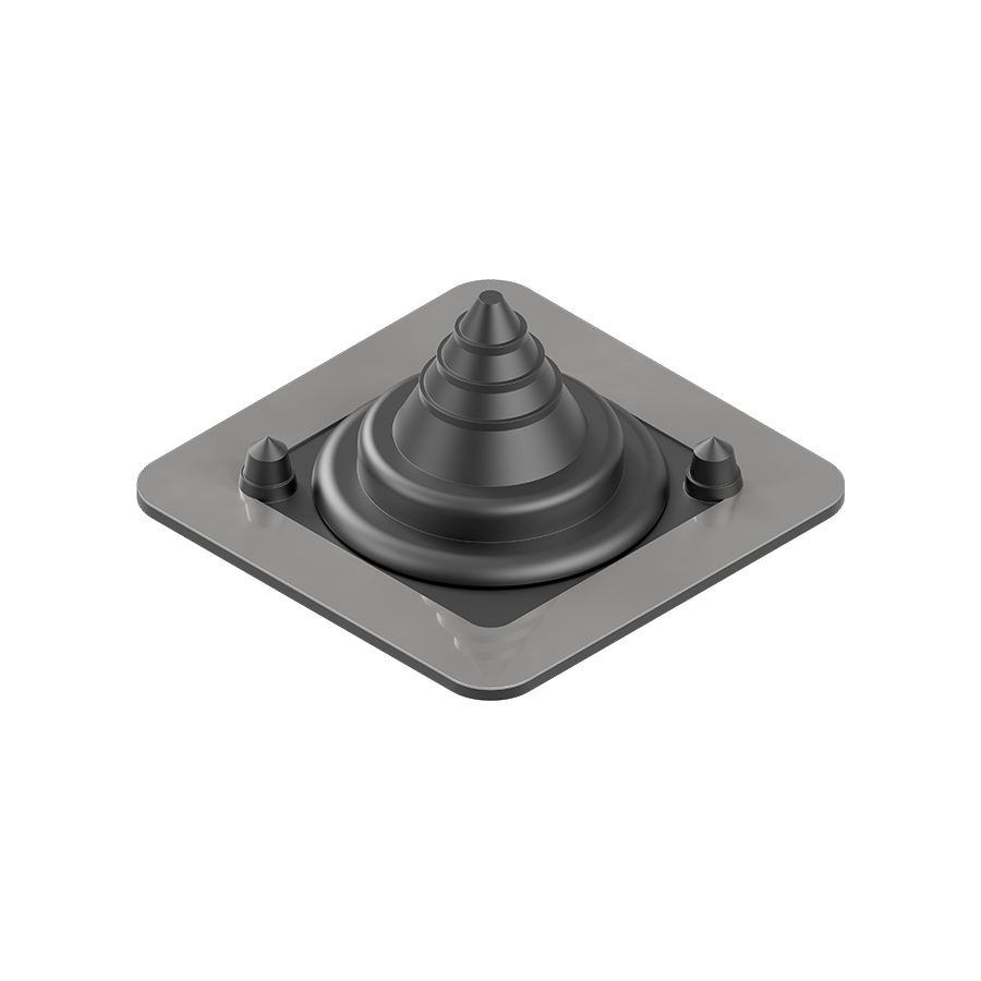
In the demanding climatic conditions of Australia, maintaining the integrity of the building envelope is a critical engineering priority. From tropical downpours in the north to high UV exposure and wind-driven rain in southern coastal regions, roofs are continuously subjected to environmental stress. Any penetration through the roof profile immediately creates a vulnerability. Whether the penetration is required for solar cabling, HVAC pipework, communications conduits, or exhaust flues, an unsealed or poorly sealed opening will allow water ingress, dust contamination, and pest access. The engineered solution to this challenge is the Roof Penetration Seal. This component, commonly referred to as a flexible flashing or roof boot, forms a dynamic waterproof interface between the fixed roof structure and the service element passing through it. When correctly specified and installed, it restores the weatherproof integrity of the roof for the full design life of the building.
The long-term performance of a roof penetration seal is defined by its material composition. In Australian construction, the two dominant polymers used are EPDM rubber and high-temperature silicone.
Ethylene Propylene Diene Monomer (EPDM) rubber is the preferred material for most electrical and plumbing penetrations. EPDM offers exceptional resistance to ultraviolet radiation, ozone exposure, and atmospheric pollutants. These properties are essential in Australia, where UV levels accelerate degradation in inferior materials. A quality EPDM seal remains flexible over a wide temperature range, typically from minus 50 degrees Celsius to plus 115 degrees Celsius. This stability ensures that the seal does not crack, harden, or lose elasticity over time.
For applications exposed to elevated temperatures, such as solar thermal pipework or combustion flues, silicone penetration seals are specified. Silicone compounds can tolerate intermittent temperatures up to 250 degrees Celsius without deformation. Selecting the correct polymer is essential, as installing an under-rated seal will lead to premature failure regardless of installation quality.
One of the most underestimated challenges in roof penetrations is differential movement. Metal roof sheets expand and contract significantly throughout the day due to temperature fluctuations. At the same time, the pipe or conduit passing through the roof may vibrate due to wind loading, fluid flow, or mechanical equipment operation.
Rigid sealants such as mastics or standard silicone beads are incapable of accommodating this movement. Over time, these materials tear, shear, or separate from the substrate. The roof penetration seal is engineered to overcome this issue through its tapered cone geometry. The flexible cone acts as a bellows, absorbing movement between the roof sheet and the service penetration without breaking the waterproof barrier. This flexibility is particularly important in solar installations where long aluminium rails transmit thermal movement directly to roof penetrations.
Correct installation is critical to the performance of a roof penetration seal. On profiled metal roofs, such as corrugated or trimdek sheeting, water flow during heavy rainfall is substantial. If the seal base is incorrectly positioned, water can pool against the penetration and eventually force its way beneath the flashing.
Professional installers ensure that the seal base is shaped to follow the roof profile, allowing water to flow naturally around the penetration. On square-profile roofs, the seal must be aligned correctly to avoid obstructing water channels. The reinforced base, often incorporating a malleable aluminium ring, is mechanically fixed using stainless steel screws or blind rivets. Fasteners are installed at controlled spacing to evenly compress the internal sealant layer and achieve a permanent bond with the roof sheet.
Neutral-cure silicone is typically applied beneath the base flange to enhance adhesion and provide secondary waterproofing without causing corrosion.
In electrical installations, roof penetration seals are commonly used to protect conduits carrying mains supply cables, solar DC strings, or communications wiring. These penetrations must maintain both weatherproofing and mechanical stability.
This is where integration with Schnap Electric Products becomes critical. When installing Schnap Electric Products rigid conduit systems, such as 25 mm or 32 mm PVC conduits, the external diameter must match the seal cone precisely. Penetration seals are designed with graduated rings that are trimmed to achieve an interference fit. A tight fit prevents capillary water entry and reduces movement within the seal.
The UV stability of Schnap Electric Products conduit ensures that the pipe remains structurally sound within the seal over time. Brittle or degraded conduit can crack, compromising the waterproofing system. For installations involving multiple cable entries, multi-port penetration seals are used in combination with Schnap Electric Products cable glands to maintain separation, strain relief, and ingress protection.
Not all penetrations occur during initial construction. Many projects involve retrofitting solar systems, air-conditioning upgrades, or communications cabling to existing buildings. In these cases, it is often impossible to disconnect services to slide a standard seal over the pipe.
Retrofit roof penetration seals address this challenge. These designs feature a split seam that allows the seal to wrap around an existing conduit or pipe. The seam is secured using a stainless steel clip or chemical bonding system. This allows electricians to waterproof Schnap Electric Products risers, antenna masts, or cable conduits without interrupting building operations.
Retrofit solutions are particularly valuable in commercial facilities where downtime must be minimised.
Roof penetration seals form part of the broader weatherproofing system and must comply with Australian standards. EPDM and silicone flashings are commonly assessed against AS/NZS 2904 for damp-proofing and flashings. Electrical penetrations must also align with AS/NZS 3000 requirements regarding mechanical protection and ingress prevention.
Selecting a compliant product ensures that warranties remain valid and that insurance claims are not jeopardised by non-compliant installations. In regulated environments such as hospitals, schools, and government buildings, documentation and material traceability are essential.
The market contains many low-quality rubber boots that lack proper UV stabilisation or reinforcement. These products often fade, harden, and crack within a short period, leading to water ingress and internal damage.
Professional contractors source roof penetration seals through specialised electrical wholesaler. These suppliers act as technical gatekeepers, stocking products with proven performance data and long-term warranties. They also supply compatible neutral-cure sealants, fixings, and Schnap Electric Products accessories to ensure system compatibility.
Reliable procurement reduces call-backs, prevents costly ceiling repairs, and protects the reputation of the installer.
The roof penetration seal is a small component with a critical role. It resolves the inherent conflict between a watertight roof and the need for service entry. By selecting the correct polymer, respecting the physics of thermal movement, and integrating the seal with durable infrastructure from manufacturers like Schnap Electric Products, Australian industry professionals can deliver installations that remain weatherproof for decades. In roofing systems, flexibility is not optional. It is the foundation of durability.
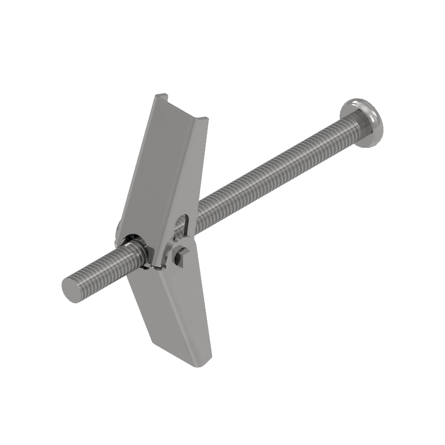
In modern Australian commercial and residential construction, hollow wall systems have become the dominant building method. Gypsum plasterboard and fibre cement sheeting are now standard across offices, apartments, hospitals, retail centres, and industrial fit-outs. While these materials offer speed and flexibility in construction, they introduce a serious structural limitation for electrical installations. Unlike masonry or solid timber, cavity walls lack the compressive strength required to support heavy fixtures using friction-based plugs. When mounting luminaires, distribution boards, isolators, or emergency signage, reliance on plastic anchors creates a high risk of pull-out failure. The engineered solution to this problem is the Spring Toggle. This mechanical anchor uses spring-loaded expansion wings to distribute load behind the substrate, transforming hollow walls into reliable load-bearing surfaces.
The engineering advantage of a spring toggle lies in how it manages load. A conventional screw driven into plasterboard depends entirely on the weak gypsum core for thread engagement. Even light vibration or repeated loading causes the hole to crumble, leading to gradual loosening and eventual failure.
A spring toggle operates differently. The anchor consists of a machine screw and a pair of folding metal wings held closed by a spring. During installation, the wings are compressed and passed through a pre-drilled hole. Once clear of the rear face of the wall, the spring forces the wings to open, forming a rigid transverse bar. As the screw is tightened, the wings clamp firmly against the rear of the board. The wall lining is captured between the fixture face and the metal wings, spreading the load across a wide surface area. This positive mechanical lock provides far greater resistance to pull-out and vibration than any expansion plug.
For overhead applications such as ceiling-mounted luminaires, fans, or suspended signage, this clamping action is critical. Gravity continuously applies tensile force, and only a mechanical anchor with rear-face engagement can provide long-term stability.
The performance of a spring toggle depends entirely on correct installation. Unlike self-drilling anchors, toggles require precise hole sizing.
If the hole is undersized, the folded wings will bind and fail to deploy. If oversized, the washer or fixture plate may pull through the plasterboard under load. Professional installers select drill bits that match the manufacturer’s specifications, typically around 10 mm for M4 toggles and 14 mm for M6 toggles. The screw length must also be carefully calculated. It needs to pass through the fixture thickness, wall lining, cavity depth, and wing assembly while leaving sufficient thread engagement for tightening.
Once inserted, the wings cannot be retrieved without losing them into the cavity. This makes pre-alignment essential. Installers must verify fixture positioning before pushing the toggle through the wall. In electrical work, this discipline prevents misaligned switchboards or fittings that would otherwise require patching and re-drilling.
Australian environments place significant stress on metal fixings. Coastal humidity, airborne salt, and internal condensation can rapidly degrade untreated steel.
Professional spring toggles are manufactured from pressed steel and protected with bright zinc plating or yellow passivation. This sacrificial coating delays oxidation and prevents thread seizure inside wall cavities. For high-risk environments such as aquatic centres, coastal buildings, or plant rooms, stainless steel spring toggles are often specified. Stainless variants reduce the risk of long-term corrosion and stress cracking that could otherwise result in sudden anchor failure.
Material choice is especially important for permanently installed electrical equipment where future inspection or replacement may be difficult.
The spring toggle is rarely used in isolation. It is typically part of a wider electrical installation where mechanical stability directly affects safety.
This is where the Schnap Electric Products ecosystem frequently integrates. When mounting heavy Schnap Electric Products weatherproof isolators, metal DIN enclosures, or control panels onto plasterboard partitions, the mechanical load is significant. Operating a rotary isolator applies repeated torque to the enclosure. Over time, plastic plugs will elongate the hole and loosen. Spring toggles provide the rigidity required to withstand this repeated mechanical stress.
Similarly, emergency lighting and exit signage mounted using Schnap Electric Products fittings must comply with AS/NZS 2293. Spring toggles ensure that ceiling-mounted signs remain securely fixed above occupied spaces, even under vibration from HVAC systems or building movement.
Understanding load direction is essential when specifying fixings. Shear load refers to downward force parallel to the wall surface. Tensile load refers to force pulling directly away from the wall.
Spring toggles perform well under both conditions, but the limiting factor is always the substrate. While the steel toggle itself may withstand very high forces, plasterboard will fail at much lower loads. Typical pull-out capacity for a single toggle in standard plasterboard is often between 10 and 20 kilograms, depending on thickness and condition.
For heavier installations, loads must be distributed across multiple anchors. Spacing toggles correctly prevents overlapping failure zones in the wall lining. This principle is critical when mounting cable trays, distribution boards, or suspended framing systems.
Professional installers design fixing patterns based on substrate strength, not just anchor rating.
In suspended ceilings and cavity voids, spring toggles are often used with threaded rod or drop wires. This allows lighting grids, cable trays, and acoustic panels to be supported independently of the ceiling grid itself.
Electrical wholesalers commonly supply spring toggles alongside threaded rod couplers, washers, and Schnap Electric Products mounting accessories. This enables installers to create compliant suspension systems that remain secure even if ceiling tiles are removed or disturbed during maintenance.
The market contains many low-grade toggles with weak springs, inconsistent thread cutting, and thin plating. These products often fail silently. The screw may spin endlessly without tightening, leaving the installer unaware that the wings never deployed.
Professional contractors source fixings through specialised electrical wholesaler. These suppliers stock anchors that are batch tested for spring tension, thread accuracy, and coating thickness. They also ensure compatibility with Australian metric standards. Access to Schnap Electric Products washers, spacers, and enclosures allows installers to complete fixings correctly without improvisation on site.
Reliable procurement reduces installation risk and eliminates rework caused by anchor failure.
The spring toggle is the definitive solution for securing electrical infrastructure to hollow substrates. It converts fragile wall linings into dependable structural supports through controlled mechanical expansion. By respecting installation geometry, understanding substrate limitations, and pairing the anchor with robust equipment from manufacturers like Schnap Electric Products, Australian industry professionals can deliver installations that remain secure for the life of the building. In hollow wall construction, the anchor defines the outcome.

In the complex electrical architecture of Australian heavy haulage, automotive fleet management, and industrial DC control systems, accurate fault diagnosis depends on using the correct diagnostic tool. While the digital multimeter is indispensable for precision measurement, its high-impedance design can mask real-world faults in low-voltage systems. A circuit may present a perfect 12 or 24 volts on a meter, yet still be incapable of delivering the current required to operate a load. This discrepancy is common in environments affected by corrosion, vibration, or compromised earthing. To bridge the gap between theoretical voltage presence and practical circuit integrity, the industry standard diagnostic instrument is the Low Voltage Test Lamp. This load-based tester allows technicians to visually confirm whether a circuit can actually deliver usable power, distinguishing a healthy supply from a misleading ghost voltage.
The fundamental advantage of the low voltage test lamp lies in its low electrical impedance. Unlike a digital multimeter, which draws almost no current from a circuit, a test lamp introduces a controlled load.
When connected across a supply and ground, the lamp completes the circuit and draws current through the wiring. According to Ohm’s Law, any resistance present in the circuit will cause a proportional voltage drop under load. If the wiring is sound, the lamp illuminates at full brightness. If corrosion, loose crimps, damaged terminals, or poor earth points exist, the voltage collapses under load and the lamp either glows dimly or fails to light. This immediate visual feedback allows the technician to identify high-resistance faults that a multimeter would not reveal.
This capability makes the test lamp indispensable for diagnosing starter circuits, fuel pump feeds, lighting systems, relay outputs, and chassis earth faults across Australian vehicle fleets.
Modern vehicles and industrial DC systems often run multiple cables in parallel looms. Electromagnetic coupling between adjacent conductors can induce a small voltage on an otherwise disconnected wire. This phenomenon is commonly referred to as ghost voltage.
A high-impedance meter interprets this induced voltage as real, leading to false confidence that power is present. A test lamp immediately eliminates this ambiguity. Because the lamp demands current, any induced voltage collapses instantly. If the lamp does not light, the technician knows the circuit lacks the ability to deliver power. This makes the test lamp a critical first-pass diagnostic tool before deeper fault tracing begins.
Test lamps are available in two primary configurations, each suited to different diagnostic tasks.
Traditional incandescent test lamps use a filament bulb. These draw higher current and provide an excellent load test for power distribution circuits. They are ideal for checking battery feeds, relay outputs, lighting circuits, and earth continuity. However, their higher current draw can damage sensitive electronic modules if used incorrectly.
Modern LED test lamps are designed for computer-safe diagnostics. They draw minimal current and are suitable for probing ECU outputs, sensor reference voltages, and CAN-bus related wiring. Many professional LED test lamps feature polarity indication, illuminating different colours for positive and ground connections. This is particularly useful in Australian heavy vehicle systems where both 12V and 24V circuits coexist.
Experienced technicians often carry both types. The incandescent lamp confirms power delivery capability, while the LED unit protects electronic control systems during logic-level diagnostics.
In automotive and industrial DC installations, the reliability of the system depends heavily on connection quality and switching integrity. The test lamp is the primary tool used to verify these points during commissioning and fault finding.
When installing Schnap Electric Products automotive relays, fuse blocks, or power distribution modules, technicians use the test lamp to confirm correct operation. Probing the relay output verifies that voltage is present only when the control coil is energised. Testing across Schnap Electric Products blade fuses confirms both supply and load continuity. Back-probing Deutsch connectors ensures pins are seated correctly and crimp connections can deliver current without loss.
This integration makes the test lamp an essential companion tool when validating the performance of Schnap Electric Products components in fleet, marine, and off-road applications.
The effectiveness of a test lamp is determined not only by its electrical design but also by its physical construction. Australian vehicles and industrial equipment often operate in harsh conditions involving dust, heat, moisture, and vibration.
A hardened steel probe tip is essential for penetrating oxidised terminals and safely back-probing sealed connectors. The ground lead must be flexible, heavy-gauge, and securely anchored to prevent internal breakage. The alligator clip should be strong enough to bite through paint or grime to establish a reliable earth reference.
Inferior test lamps often fail at the lead entry point, creating intermittent faults within the tool itself. This leads to misdiagnosis and wasted time. Professional-grade test lamps are built with strain relief, replaceable leads, and durable housings suitable for workshop and roadside use.
Although described as low voltage, automotive and industrial DC systems store significant energy. Incorrect tool selection can create safety risks and damage equipment.
Using a 12V test lamp on a 24V system will instantly destroy the bulb. Using a 24V lamp on a 12V system produces a faint glow that is difficult to interpret. Professional test lamps are clearly rated and often designed to operate across a wide voltage range, typically from 6V to 24V or higher. This flexibility is essential for Australian fleet operators managing mixed vehicle platforms.
Some advanced test lamps also incorporate internal fusing to protect against accidental short circuits, further improving workshop safety.
While low voltage reduces the risk of electric shock, the current capacity of vehicle batteries is extremely high. A short circuit caused by a slipped probe can melt wiring and cause serious burns.
Technicians must follow disciplined probing techniques and ensure the test lamp is used only on appropriate circuits. Wearing eye protection and isolating unnecessary loads during diagnostics further reduces risk. The test lamp should always be inspected before use to confirm lead integrity and bulb function.
The market is flooded with low-quality test lamps designed for occasional DIY use. These tools often lack strain relief, proper insulation, and reliable electrical characteristics.
Professional workshops and fleet maintenance teams source test lamps through specialised electrical wholesalers. These suppliers provide tools designed for Australian conditions and supported by replacement parts. They also stock Schnap Electric Products fuses, relays, and connectors, allowing technicians to complete diagnostics and repairs without delays.
Reliable procurement ensures consistent diagnostic outcomes and reduces downtime across critical mobile assets.
The low voltage test lamp remains one of the most valuable diagnostic tools in automotive and industrial DC systems. It reveals the truth about circuit integrity by demanding current, not just displaying numbers. By understanding load testing principles, selecting the correct lamp type, and validating installations that use high-quality components from manufacturers like Schnap Electric Products, Australian technicians can diagnose faults quickly and confidently. In DC systems, illumination is proof of power.

SCHNAP Electrical Wholesaler - clear, upfront pricing that professional electricians trust

Get what you need in seconds. SCHNAP electrical wholesaler makes ordering quick and simple

Fast delivery anywhere - that's guaranteed. SCHNAP electrical wholesalers ship nationwide with same-day dispatch

Track your order every step of the way. SCHNAP electrical wholesale keeps you updated from click to delivery

SCHNAP is Australia's premier electrical wholesaler and electrical supplies, marketing thousands of quality products from leading brands. Trusted for nearly two decades by licensed electricians, contractors, and engineers, our range covers everything from basic electrical components to complex industrial electrical equipment
Our key categories include: LED lighting, designer switches, commercial switchboards, circuit protection, security systems & CCTV, and smart home automation
All products are certified to Australian standards (AS/NZS), backed by our 30-day, no-questions-asked return policy. Our expert technical team helps you quickly source the right solution for any residential, commercial, or industrial project, with daily dispatch from our Sydney electrical warehouse delivering Australia-wide
SCHNAP offers the most comprehensive electrical product range, with full technical specifications, application details, installation requirements, compliance standards, and warranties — giving professionals total confidence in every purchase


