




Kingsgrove Branch:
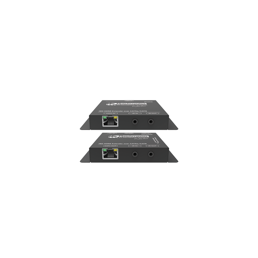
In commercial audiovisual design and high-end residential integration across Australia, one constraint continues to shape system architecture more than any other: distance. While HDMI is the universal interface for digital video and audio, it was never engineered for long cable runs. As resolutions increase from 1080p to 4K and beyond, the limitations of passive copper HDMI cabling become more severe. In practical terms, a standard HDMI cable becomes unreliable beyond 10 to 15 metres, often exhibiting signal dropouts, intermittent “sparkles,” or complete loss of handshake between source and display.
For installations where the source equipment is centrally located in a rack room and the display is tens of metres away, direct HDMI cabling is no longer viable. This scenario is common in corporate offices, lecture theatres, hospitality venues, and large residences. The professional engineering response to this challenge is the HDMI Extender Over Cat 6. By converting HDMI into a format suitable for structured cabling, this solution allows uncompressed high-definition video, audio, and control signals to be transmitted reliably over distances of up to 100 metres.
The most widely adopted technology behind HDMI extenders over Cat 6 is HDBaseT. Unlike IP-based video distribution systems, which compress video into data packets and introduce latency, HDBaseT transports the HDMI signal in an uncompressed form. This distinction is critical in environments where image quality, responsiveness, and synchronisation are non-negotiable.
An HDBaseT system consists of a transmitter located at the source and a receiver positioned behind the display. The transmitter converts the HDMI TMDS signal into a pulse-amplitude modulated waveform optimised for twisted pair cabling. This signal can carry up to 18 Gbps of bandwidth, sufficient for 4K Ultra HD at 60 Hz with full colour depth. At the receiver end, the signal is reconstructed back into standard HDMI, delivering a bit-accurate image with zero perceptible latency.
The performance of an HDMI extender is only as good as the cabling infrastructure it relies upon. While some extenders may function over Category 5e in limited scenarios, Cat 6 or Cat 6A cabling is the professional minimum standard for reliable 4K transmission.
Category 6 cable features tighter twist rates and improved insulation, which significantly reduce near-end and far-end crosstalk. These characteristics are essential for preserving signal integrity at high frequencies. Equally important is the conductor material. Solid-core, pure copper cable must be used for permanent runs. Copper clad aluminium introduces resistance and timing skew that can prevent extenders from synchronising correctly, leading to intermittent failures that are difficult to diagnose after installation.
Patch cords should be limited to short lengths between wall plates and devices. Long runs of stranded cable increase attenuation and undermine the benefits of HDBaseT technology.
One of the defining advantages of HDMI extenders over Cat 6 is the use of Power over Cable, often referred to as PoC or Power over HDBaseT. In a conventional setup, both the transmitter and receiver require separate power supplies, which complicates installation and often necessitates additional electrical work behind displays.
With PoC, the transmitter injects low-voltage DC power into the Cat 6 cable, supplying the receiver remotely. This approach eliminates the need for a power outlet behind the screen, making it ideal for slimline wall-mounted displays and video walls. From an integration perspective, this reduces labour costs, simplifies compliance, and improves the visual finish of the installation.
While transmitters and receivers attract the most attention, passive components play an equally critical role in system stability. Every termination, wall plate, and patch panel introduces potential impedance discontinuities. Poor termination quality can cause signal reflections that degrade the eye pattern and reduce system headroom.
This is where the broader infrastructure ecosystem from Schnap Electric Products becomes relevant. High-quality Category 6 data jacks and faceplates are engineered to preserve pair twist integrity right up to the point of termination. Proper cable management accessories help maintain minimum bend radius and prevent mechanical stress, both of which are essential for long-term performance.
Modern HDMI extenders are not limited to video and audio transport. Professional-grade systems support bidirectional control channels, enabling full system integration. Infrared pass-through allows remote control commands to travel from the display back to the source, while RS-232 support enables integration with automation systems.
In a boardroom or lecture theatre, this means that equipment can remain hidden in a secure rack while remaining fully controllable from the user interface at the front of the room. This capability is central to clean AV design and is a key differentiator between professional extenders and consumer-grade alternatives.
High-bandwidth Digital Content Protection is a frequent source of failure in HDMI distribution systems. Modern content sources require HDCP 2.2 compliance to output 4K material. If any device in the signal chain fails to authenticate correctly, the source will block the video signal entirely.
Professional HDMI extenders over Cat 6 are designed to manage HDCP handshakes transparently. Inferior devices often advertise 4K support but fail under real-world conditions, resulting in black screens or intermittent image loss. Ensuring full HDMI 2.0 and HDCP 2.2 compatibility is essential for commercial reliability.
The market contains a wide range of low-cost extenders often described as “baluns.” These devices may function in controlled environments but lack the shielding, firmware stability, and compliance required for permanent installation.
Professional integrators mitigate this risk by sourcing through electrical wholesaler. These suppliers ensure equipment is RCM compliant for the Australian market and supported by local warranty channels. They also provide access to testing tools and compatible cabling, allowing installers to verify Cat 6 performance before commissioning the active hardware.
The HDMI extender over Cat 6 has become a foundational element of modern AV system design. It removes the distance limitations of native HDMI, enabling centralised equipment layouts and clean architectural outcomes. By understanding the physics of HDBaseT transmission, insisting on high-quality structured cabling, leveraging power over cable technology, and supporting installations with professional infrastructure from manufacturers like Schnap Electric Products, Australian integrators can deliver robust, high-performance video distribution across any building. In long-distance digital transmission, disciplined engineering at every layer is what transforms possibility into reliability.
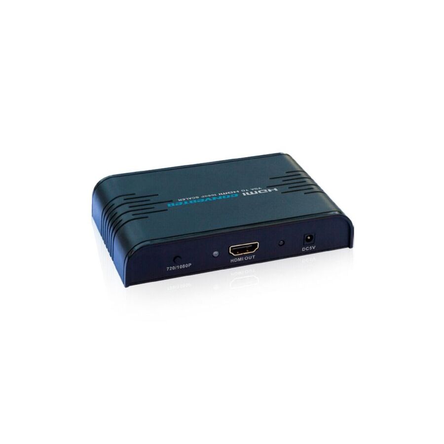
In the rapidly evolving Australian audiovisual landscape, a persistent challenge exists at the intersection of legacy infrastructure and modern display technology. While contemporary commercial environments have standardised on HDMI for video distribution, a significant portion of critical backend equipment remains dependent on the Video Graphics Array standard. Industrial control systems, building management interfaces, medical imaging consoles, legacy servers, and security Digital Video Recorders often output only VGA. At the same time, modern flat-panel displays, LED walls, and projectors increasingly omit analog inputs altogether.
For system integrators, replacing functional legacy equipment is rarely economical or operationally practical. The engineering requirement is not replacement, but translation. This is where the VGA to HDMI upscaler becomes indispensable. Unlike a passive adaptor, this device is an active signal processor that converts analog video into digital form, scales the image to a modern resolution, embeds audio where required, and delivers a stable HDMI output compatible with today’s displays.
The first task of a VGA to HDMI upscaler is signal type conversion. VGA is an analog standard that transmits Red, Green, and Blue colour channels as continuous voltage levels, accompanied by horizontal and vertical synchronisation pulses. HDMI, by contrast, is a fully digital protocol that transmits binary data using Transition Minimized Differential Signaling.
To bridge this gap, the upscaler relies on a high-performance Analog-to-Digital Converter. The ADC samples the incoming voltage waveform thousands of times per second, converting each sample into digital values. The precision of this process determines image quality. Insufficient sampling resolution results in colour banding, shimmering edges, or unstable images. Professional upscalers are designed to lock onto a wide range of VESA standard timings and stabilise sync signals before conversion, ensuring consistent digitisation even from aging or electrically noisy VGA sources.
Conversion alone does not solve the problem. Most VGA sources output resolutions such as 800×600, 1024×768, or 1280×1024. When displayed on a 1920×1080 or 4K screen without proper processing, these images appear soft and poorly defined.
The scaler engine inside a VGA to HDMI upscaler performs mathematical interpolation to expand the original pixel grid. Using algorithms such as bilinear or bicubic scaling, the device generates additional pixels based on surrounding data, effectively reconstructing the image to match the native resolution of the display. This process significantly improves readability, particularly for text-heavy interfaces like industrial HMIs or legacy server dashboards. For control rooms and technical environments, clarity is not aesthetic. It is operationally critical.
Another challenge lies in aspect ratio mismatch. VGA systems were largely designed around a 4:3 format, while modern displays use a 16:9 widescreen layout. Without proper handling, images are stretched horizontally, distorting graphics and undermining usability.
Professional VGA to HDMI upscalers provide aspect ratio control options. Integrators can maintain the original 4:3 geometry by adding pillar-box bars to the sides of the widescreen output. This preserves the intended proportions of diagrams, schematics, and user interfaces. In applications such as medical imaging, engineering visualisation, or security monitoring, geometric accuracy is essential and cannot be compromised for screen fill.
VGA carries video only. HDMI expects both video and audio in a single stream. To achieve full compatibility, the upscaler must embed audio into the HDMI output.
Most professional units include an analogue audio input, typically via a 3.5 mm stereo jack. The device digitises this signal and synchronises it with the processed video stream. Because video scaling introduces processing delay, audio must be time-aligned to avoid lip-sync errors. High-quality upscalers manage this internally, ensuring audio remains locked to the video even during dynamic resolution changes.
Latency is often overlooked in conversion devices. Consumer-grade converters may introduce several frames of delay, which is unacceptable in interactive environments. Cursor movement, touchscreen interaction, or live monitoring becomes sluggish and frustrating.
Professional VGA to HDMI upscalers are designed for low-latency operation, typically adding no more than one to two frames of delay. This makes them suitable for real-time applications such as control rooms, surveillance systems, and live presentation environments where responsiveness is critical.
As active devices, VGA to HDMI upscalers require external power. Depending on the model, this may be supplied via USB or a dedicated DC adaptor. Stable power delivery is essential, as voltage fluctuations can destabilise the scaler chip and cause intermittent signal loss.
This is where the broader infrastructure ecosystem from Schnap Electric Products becomes relevant. High-quality HDMI leads are required to carry the upscaled digital signal without introducing handshake failures or sparkles. Surge-protected power distribution helps shield sensitive electronics from electrical noise, particularly in industrial environments where motors, lifts, and heavy machinery share the same supply. Proper mounting accessories ensure the upscaler is secured behind displays or within racks, preventing mechanical strain on legacy VGA ports.
The market is saturated with low-cost VGA converters that lack proper scaling engines, introduce excessive latency, or fail electromagnetic compatibility requirements. These devices may work temporarily but often degrade under continuous operation.
Professional AV integrators mitigate this risk by sourcing equipment through specialised electrical wholesaler. These suppliers ensure products meet Australian regulatory standards and are suited to long-term commercial deployment. They also provide access to compatible cabling, mounting hardware, and test equipment, allowing installations to be completed to a professional standard rather than improvised on site.
The VGA to HDMI upscaler is a critical enabler of continuity in modern AV systems. It allows organisations to preserve the value of reliable legacy equipment while embracing modern display technology. By understanding analog-to-digital conversion physics, prioritising high-quality scaling, managing aspect ratios correctly, and supporting installations with robust infrastructure from manufacturers like Schnap Electric Products, Australian industry professionals can deliver seamless, high-definition integration across generations of technology. In commercial AV, intelligent adaptation is often more valuable than replacement.
In the complex landscape of Australian commercial audiovisual integration, the need to manage multiple high-definition video sources and distribute them to multiple displays is no longer a luxury. It is a baseline operational requirement. Sports venues demand the ability to route different live events to different screens instantly. Corporate facilities require flexible presentation switching between laptops, video conferencing systems, and signage players. Education campuses rely on centralised control to manage lecture theatres, overflow rooms, and recording systems.
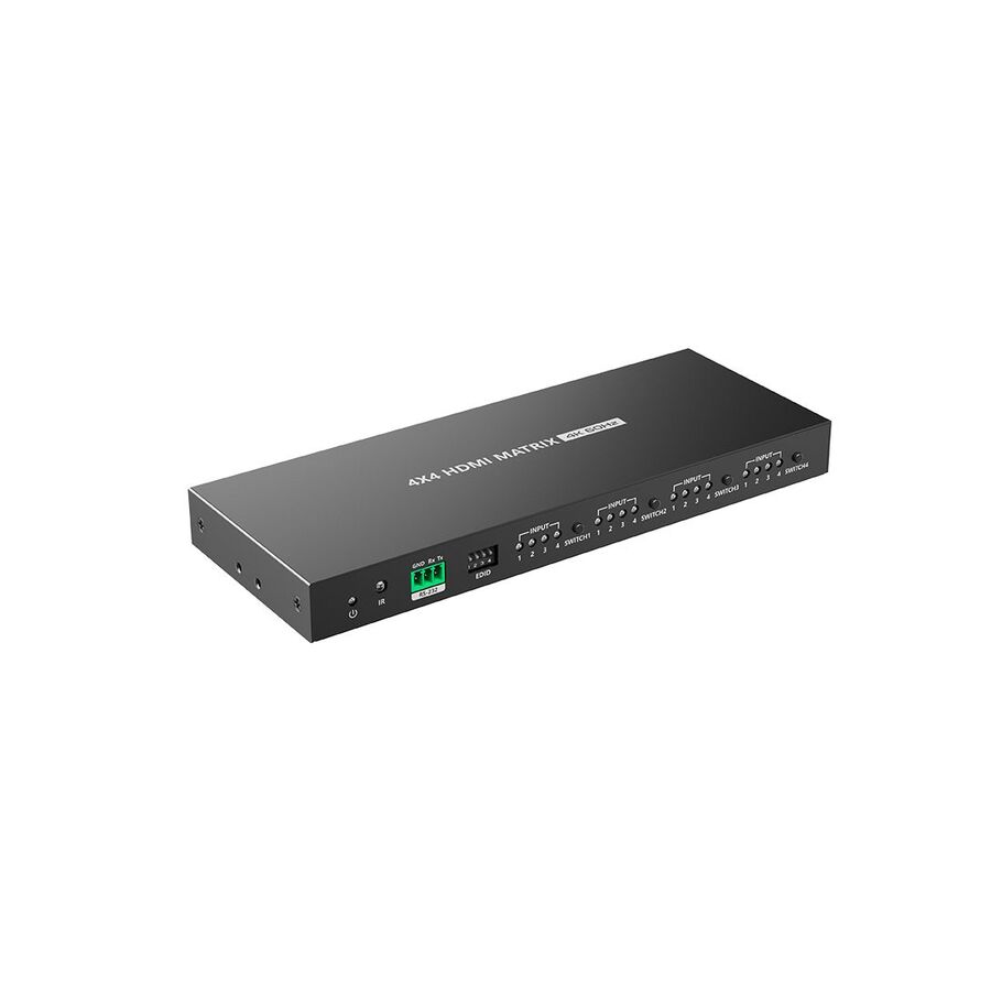
Simple point-to-point cabling cannot support this level of flexibility. Even basic switchers and splitters fall short because they restrict signal flow to one-to-many or many-to-one paths. The engineering solution that enables true any-input-to-any-output routing is the HDMI matrix switch. This device forms the logical and physical core of the AV system, allowing multiple HDMI sources to be routed independently or simultaneously to multiple display endpoints without signal degradation or delay.
At its core, an HDMI matrix switch is built around a non-blocking cross-point architecture. In a typical 4x4, 8x8, or larger configuration, every input can be mapped to any output, regardless of how other routes are configured. This requires more than simple switching. It demands high-speed internal signal management capable of maintaining HDMI timing accuracy.
HDMI signals rely on Transition Minimized Differential Signaling. As data passes through the matrix backplane, it must be re-clocked and equalised to remove jitter and compensate for internal trace length variation. Professional-grade matrices use high-bandwidth internal buses rated at 18Gbps or higher to support 4K Ultra HD at 60Hz with full colour sampling and HDR metadata. Without sufficient internal headroom, switching delays, image sparkles, or complete signal loss can occur.
Zero-latency switching is a defining requirement. Unlike IP-based video distribution, an HDMI matrix does not compress or packetise the signal. The output is a bit-perfect replica of the input, making the matrix suitable for live broadcast, gaming, and real-time presentation environments.
One of the most challenging aspects of HDMI matrix deployment is Extended Display Identification Data management. EDID defines the resolution, refresh rate, colour depth, and audio formats that a display can accept. In a direct connection, this process is simple. In a matrix environment, it becomes complex.
Consider a venue where a single source must feed both a 4K LED wall and an older 1080p monitor. If unmanaged, the source may detect the lower-resolution display and reduce output quality for all connected screens. Professional HDMI matrix switches address this through advanced EDID control.
Integrators can select predefined EDID profiles, upload custom EDID data, or force the matrix to present a virtual display capability to the source. In more advanced systems, individual outputs include internal scalers that downscale the signal for legacy displays while preserving native resolution on premium screens. This capability is critical in retrofit projects where infrastructure upgrades are staged over time.
High-bandwidth Digital Content Protection governs the legal transmission of protected video content. An HDMI matrix switch operates as an HDCP repeater, sitting between the source and multiple displays. It must decrypt the incoming stream and re-encrypt it for each output independently.
Modern content sources require HDCP 2.2 compliance for 4K playback. If any device in the chain fails authentication, the source will block the signal entirely. High-quality matrices include robust HDCP key storage and management engines that allow simultaneous authentication across all outputs. Inferior devices may pass handshake intermittently, resulting in flickering, blank screens, or green artefacts.
For commercial venues displaying subscription television, streamed content, or protected media, HDCP reliability is non-negotiable.
In professional installations, HDMI matrix switches are rarely operated manually. They are integrated into central control systems that manage the entire room or building.
Most commercial-grade matrices support multiple control interfaces, including RS-232 serial, infrared, and Ethernet-based IP control. This allows integration with building automation and AV platforms. Control systems can issue routing commands, monitor status, and provide user-friendly touch panel interfaces that abstract the complexity of the matrix from the end user.
Bidirectional communication ensures system awareness. When a route changes, the control system receives confirmation, maintaining synchronisation between physical signal paths and user interface feedback.
HDMI matrix switches are rack-mounted devices that generate heat and carry substantial cabling loads. Poor physical installation can compromise long-term reliability.
This is where the infrastructure ecosystem from Schnap Electric Products becomes important. Proper rack shelves, rear cable support rails, and strain relief prevent HDMI connectors from bearing the weight of multiple heavy cables. Power conditioning is equally critical. Voltage transients from HVAC systems or lift motors can disrupt matrix operation or damage internal logic. Rack-mounted power rails with surge suppression protect the investment and reduce downtime.
Thermal management must also be considered. Adequate ventilation and airflow spacing ensure that the matrix can operate continuously in 24/7 environments without thermal throttling or shutdown.
The market contains many consumer-grade HDMI matrix devices that appear suitable on paper but lack the durability required for commercial use. These units often suffer from poor heat dissipation, unstable firmware, and limited HDCP compatibility.
Professional AV integrators mitigate this risk by sourcing equipment through specialised electrical wholesaler. These suppliers ensure Regulatory Compliance Mark certification for Australian electrical and electromagnetic standards, provide firmware support, and offer local warranty coverage. They also supply compatible cabling and accessories, ensuring the entire system operates as a cohesive platform rather than a collection of mismatched components.
The HDMI matrix switch is the command centre of modern commercial AV systems. It enables precise, flexible control of visual content across diverse spaces and audiences. By understanding cross-point architecture, mastering EDID and HDCP management, integrating robust control systems, and supporting the hardware with quality rack infrastructure from manufacturers like Schnap Electric Products, Australian industry professionals can deliver AV systems that are powerful, scalable, and dependable. In complex environments, the matrix is not just a switch. It is the system controller.
In the diverse architectural landscape of Australian commercial and residential property, audiovisual integration is often constrained by the building itself. Heritage-listed façades, asbestos-containing wall cavities, post-tensioned concrete slabs, and modern glass-partitioned interiors regularly prohibit drilling or surface conduit. In these environments, running HDMI or structured cabling is either unsafe, illegal, or aesthetically unacceptable.
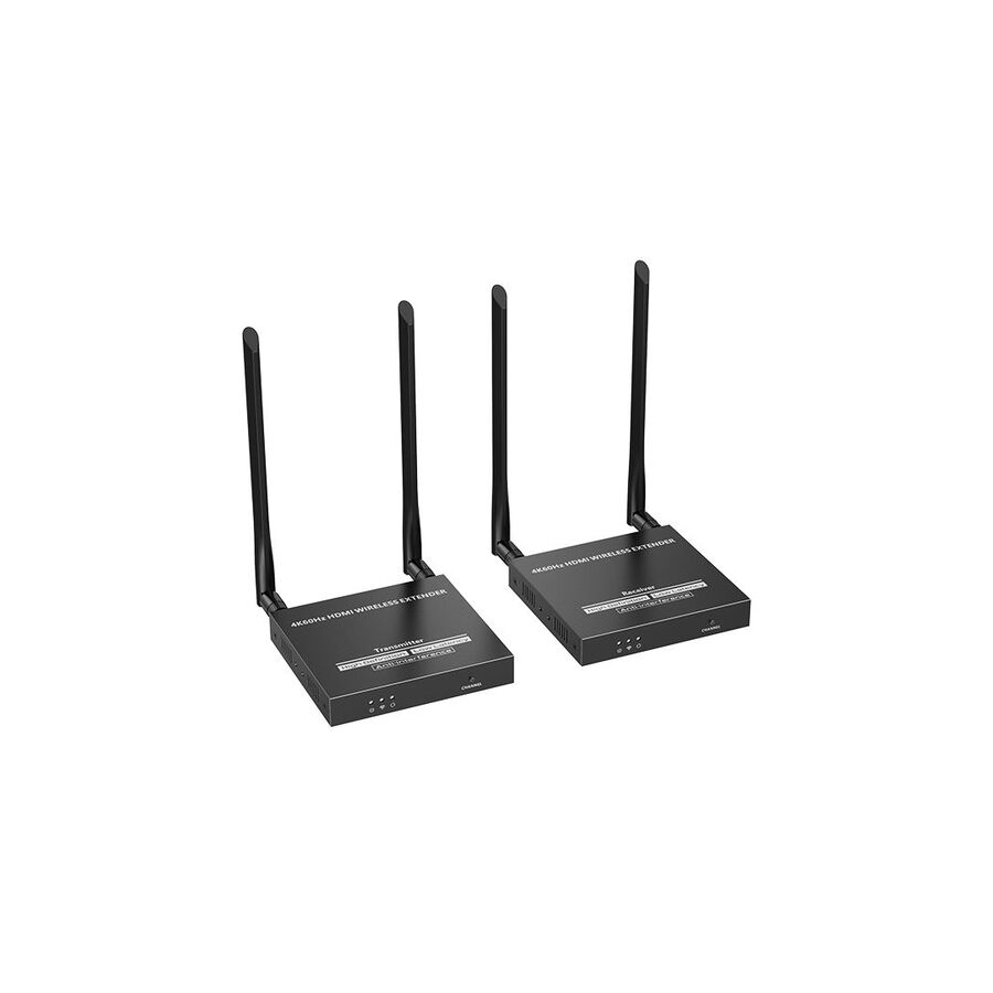
When physical infrastructure cannot be modified, the professional solution is the HDMI wireless extender. Unlike consumer casting devices designed for casual streaming, a professional wireless extender establishes a dedicated point-to-point video link between a source and a display. It replaces copper or fibre with radio frequency transmission while maintaining predictable latency, stable bandwidth, and deterministic behaviour required in corporate, education, and hospitality settings.
Wireless video performance is dictated by the physics of radio propagation. In professional HDMI wireless extenders, two frequency bands dominate: 5GHz and 60GHz. Each serves a distinct application profile.
Systems operating in the 5GHz band use wavelengths capable of passing through plasterboard, light timber framing, and furniture. This makes them suitable for residential and light commercial retrofits where the source and display are separated by one or two walls. However, 5GHz is a crowded spectrum. Wi-Fi access points, laptops, phones, and IoT devices all compete for airtime. While modern extenders use proprietary modulation and channel management to improve stability, interference remains a design consideration.
At the other end of the spectrum, 60GHz millimetre-wave systems behave very differently. These signals cannot penetrate walls and behave more like light than traditional radio waves. Their advantage lies in enormous available bandwidth. This allows transmission of uncompressed or near-uncompressed video with latency measured in microseconds rather than milliseconds. As a result, 60GHz extenders are the preferred choice for in-room presentation systems, interactive whiteboards, and boardrooms where cursor lag or lip-sync delay is unacceptable.
Latency and Compression Trade-Offs
Bandwidth determines how much compression is required. A raw 1080p60 signal requires several gigabits per second. Most wireless systems cannot sustain this rate without compression.
Entry-level wireless extenders apply H.264 compression similar to online streaming platforms. While efficient, this introduces visible artefacts and latency that can exceed 200 milliseconds. For digital signage or passive display content, this delay is usually acceptable. For live presentations, video conferencing, or interactive demonstrations, it is not.
Higher-end HDMI wireless extenders use visually lossless or line-based compression techniques. These reduce bandwidth without altering visible pixel data and keep latency below the threshold of human perception. Correct specification depends on the application. Engineers must define whether the system is intended for passive viewing or interactive use before selecting a technology platform.
Wireless video links must coexist with other RF systems. In dense urban environments, spectrum congestion is a reality. Professional HDMI wireless extenders mitigate this through dynamic channel management.
Advanced systems continuously scan the RF environment and evaluate signal-to-noise ratios. If interference is detected, the extender shifts to a cleaner channel without interrupting the video stream. This process, known as Dynamic Frequency Selection, is essential in offices, hotels, and education campuses where wireless conditions change throughout the day.
Millimetre-wave systems reduce interference risk by operating in a less congested band, but they require clear line-of-sight. Placement accuracy is critical. Minor misalignment can degrade signal quality, so careful mounting and commissioning are required.
Although the video path is wireless, the transmitter and receiver remain physical devices requiring stable power and secure mounting. Voltage fluctuation can affect RF oscillators and cause link instability.
This is where the support ecosystem from Schnap Electric Products becomes relevant. Powering wireless extenders through surge-protected outlets reduces the risk of dropouts caused by transient voltage events. In display installations, recessed mounting solutions and cable management accessories ensure that receivers and power packs fit neatly behind wall-mounted screens without mechanical stress.
Short, high-quality HDMI patch leads are also critical. Poor shielding can allow the HDMI signal itself to radiate interference into the wireless module. Proper strain relief prevents connector fatigue, which is a common failure point in retrofit installations.
Wireless transmission in Australia is regulated by the Australian Communications and Media Authority. Devices must operate within defined frequency bands and power limits under class licence conditions. Non-compliant equipment can interfere with radar, telecommunications, or emergency services.
Professional HDMI wireless extenders sold through authorised Australian channels carry the Regulatory Compliance Mark, indicating compliance with ACMA standards. Integrators must avoid grey-market imports designed for overseas frequency allocations. The legal and operational risk of non-compliant RF equipment far outweighs any short-term cost savings.
Successful deployment of a wireless extender requires realistic assessment of the environment. Wall composition, ceiling height, reflective surfaces, and human traffic all influence RF behaviour.
For 5GHz systems, wall density and neighbouring networks are key considerations. For 60GHz systems, line-of-sight and mounting stability are paramount. In both cases, pre-installation testing is recommended. Many professional extenders include signal strength indicators or alignment tools to assist commissioning.
Wireless does not eliminate planning. It replaces cable routing complexity with RF engineering discipline. When deployed correctly, it provides reliable, repeatable performance.
Wireless extenders are active electronic devices with firmware, RF components, and power regulation circuits. Long-term reliability depends on build quality, thermal design, and ongoing manufacturer support.
Electrical wholesaler act as technical gatekeepers in this space. They supply ACMA-approved hardware, firmware updates, and compatible accessories. They also provide guidance on matching extender capabilities to project requirements, reducing the risk of under-specification or over-engineering.
The HDMI wireless extender is a critical tool for modern retrofit AV projects. It enables high-definition video distribution where cabling is impractical or prohibited, without compromising usability or aesthetics. By understanding RF propagation physics, selecting the appropriate frequency band, managing latency expectations, and supporting the installation with quality infrastructure from manufacturers like Schnap Electric Products, Australian industry professionals can deliver wireless video systems that are stable, compliant, and fit for purpose. In challenging buildings, wireless is not a compromise. It is a specialised engineering solution.
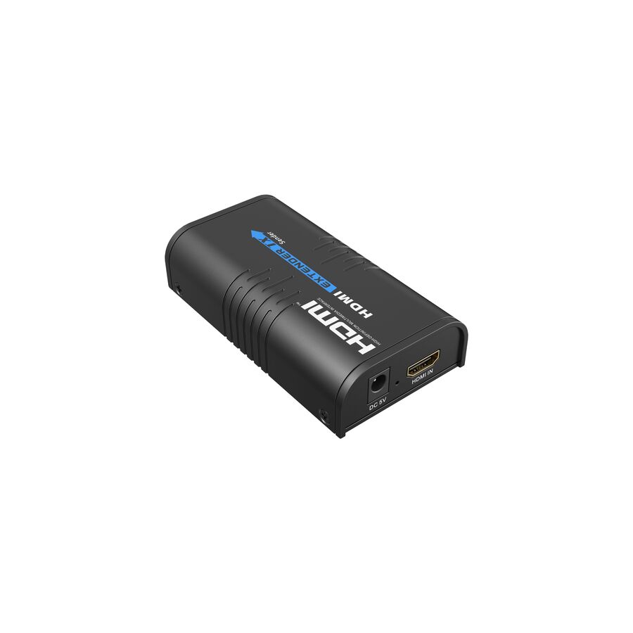
In the architecture of modern Australian audiovisual systems, the success of a distributed video link is ultimately determined at the display endpoint. While system designers often concentrate on matrix switches, transmitters, and rack-side infrastructure, the reliability of the entire signal chain depends equally on the HDMI Receiver Unit. This device, commonly referred to as the Rx module, is responsible for translating long-distance digital transmission back into a native HDMI signal that a display can render accurately and consistently.
The HDMI receiver unit is not a passive adapter. It is an active electronic component that reconstructs high-speed data, negotiates power delivery, manages content protection, and interfaces with control systems. In commercial environments such as corporate boardrooms, lecture theatres, hospitals, and digital signage networks, the receiver unit defines the quality of the “last mile” connection. Any instability at this point undermines the performance of the entire AV system.
In a typical HDBaseT or similar structured-cabling architecture, the HDMI signal undergoes significant transformation before it reaches the display. At the transmitter, the native HDMI signal is converted into a modulated format suitable for long-distance transport over Category 6 cabling. This signal is subject to attenuation, crosstalk, and electromagnetic noise as it travels through ceiling spaces and wall cavities.
The HDMI receiver unit acts as the inverse engine of this process. Its internal chipset performs clock recovery, data equalisation, and error correction to reconstruct a clean Transition Minimized Differential Signaling data stream. This process is time-critical. If the receiver cannot accurately realign the pixel clock, visual artefacts such as sparkles, intermittent black frames, or total signal loss will occur. Professional-grade receiver units are engineered with sufficient processing headroom to support 4K Ultra HD at 60Hz, ensuring stable image reproduction even under marginal cabling conditions
One of the major advantages of modern HDMI receiver units is their ability to operate without a local power supply. Through Power over HDBaseT or Power over Cable standards, the receiver negotiates DC power from the transmitter across the same Category 6 cable carrying the video signal. This eliminates the need for a General Power Outlet behind wall-mounted or recessed displays, which is often impractical in commercial fit-outs.
However, this convenience introduces thermal considerations. The receiver unit contains active silicon performing continuous decoding, decryption, and power conversion. In confined spaces behind slim displays, heat accumulation can lead to instability or thermal shutdown. Best practice requires that the receiver is mounted with adequate ventilation and mechanical support. The Schnap Electric Products ecosystem supports this requirement through ventilated mounting solutions, cable management accessories, and strain-relief systems that allow the receiver to remain secure while maintaining airflow.
Content protection is a non-negotiable requirement in modern AV systems. The HDMI receiver unit is a key participant in the High-bandwidth Digital Content Protection handshake. When protected content is transmitted, the receiver must authenticate with the display and relay confirmation upstream to the source or matrix switch. If the receiver does not support the correct HDCP version, typically HDCP 2.2 for 4K content, the entire system will fail, resulting in a black screen.
In addition to HDCP, the receiver manages Extended Display Identification Data. It reads the display’s capabilities, including resolution, refresh rate, colour depth, and audio formats, and communicates this information back to the source. Accurate EDID handling ensures that the source outputs a compatible signal. Poor EDID management can force displays into unsupported modes or limit resolution unnecessarily, degrading the user experience.
In professional installations, the HDMI receiver unit is often more than a video endpoint. It serves as a control interface between automation systems and the display. Most commercial receivers provide ports for Infrared and RS-232 control, allowing commands to travel bi-directionally across the same Category 6 cable as the video signal.
This integration enables centralised control of display power, input selection, volume, and status monitoring. For example, a control processor can send a “Power On” command through the transmitter, across the structured cabling, and out of the receiver directly into the display. Feedback from the display can travel back along the same path, allowing the system to confirm successful operation. This bidirectional communication is essential for synchronised, reliable AV systems in meeting rooms and educational facilities.
The physical HDMI patch lead connecting the receiver to the display is often overlooked, yet it is critical. Even a short, low-quality HDMI cable can introduce impedance mismatch, poor shielding, or mechanical strain that destabilises the signal. Wall-mounted displays place constant stress on connectors, especially if cable weight is unsupported.
High-quality HDMI patch leads with proper shielding, robust strain relief, and certified bandwidth performance are essential at this final connection. Schnap Electric Products supplies high-speed HDMI leads designed specifically for permanent installations, along with recessed wall plates and brush systems that preserve bend radius and protect the integrity of the structured cabling.
Receiver units are frequently installed in locations that are difficult to access once the system is complete. A frozen or unstable receiver often requires removing a heavy commercial display from the wall, creating safety risks and downtime. For this reason, reliability and firmware stability are as important as raw performance.
Professional AV integrators mitigate this risk by sourcing matched transmitter and receiver pairs through specialised electrical wholesaler. These suppliers ensure compatibility, regulatory compliance, and ongoing firmware support. They also provide access to mounting accessories and testing tools that allow installers to verify signal quality at the endpoint before system handover.
The HDMI receiver unit is the silent anchor of distributed audiovisual systems. It performs the complex tasks of signal reconstruction, power negotiation, content authentication, and control integration, all within a compact enclosure behind the display. By understanding the physics of decoding, managing thermal and power constraints, and supporting the installation with professional infrastructure from manufacturers like Schnap Electric Products, Australian industry professionals can deliver AV systems that are stable, scalable, and visually flawless. In modern AV design, the quality of the experience is defined at the endpoint, and the receiver unit is where that experience is ultimately secured.
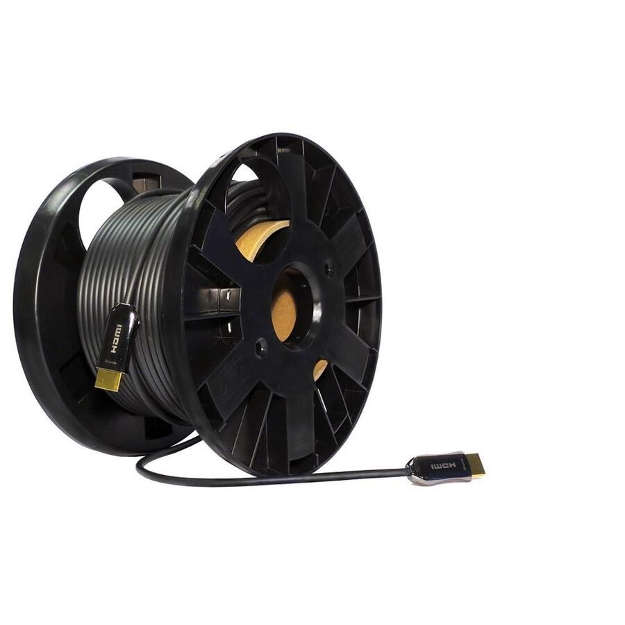
In the evolving landscape of Australian audiovisual integration, the limitations of traditional copper HDMI cabling have become one of the most significant constraints on system design. As commercial environments move rapidly from Full HD to 4K Ultra HD, and increasingly toward 8K and high-frame-rate content, the data rates demanded of interconnects have escalated dramatically. Where 1080p required under 5 Gbps, 4K at 60Hz with full colour resolution demands 18 Gbps, and HDMI 2.1 pushes this to 48 Gbps. At these frequencies, copper conductors struggle to maintain signal integrity over distance, resulting in the well-known digital cliff where images drop out entirely rather than degrading gracefully.
To overcome this limitation without introducing bulky extender boxes, external power injectors, or compressed transmission methods, the industry has adopted the HDMI Active Optical Cable. This technology replaces electrical transmission with light for the most demanding signal paths, enabling uncompressed, zero-latency video delivery over distances exceeding 100 metres. For commercial AV designers, this fundamentally changes how equipment rooms, displays, and control spaces can be planned.
An HDMI Active Optical Cable is not a simple fibre lead with HDMI plugs. It is a hybrid, active device containing both optical and copper elements, as well as miniature electronics embedded within the connector heads. High-speed TMDS video and audio channels are transmitted over multimode glass fibres, typically OM3-grade, while lower-speed control and power signals remain on copper conductors.
At the source end, an integrated conversion chipset transforms the electrical HDMI signal into pulses of light using Vertical-Cavity Surface-Emitting Lasers. These photons travel down the fibre core without resistance, unaffected by attenuation or impedance variation. At the display end, a photodiode converts the light back into an electrical signal that the HDMI receiver can decode. Meanwhile, copper conductors handle EDID communication, HDCP authentication, hot-plug detection, and the 5V power rail. This division of labour allows the cable to retain full HDMI compatibility while eliminating the distance limitations of copper for high-bandwidth data.
One of the most valuable characteristics of an active optical cable in Australian commercial environments is its immunity to electromagnetic and radio-frequency interference. Copper HDMI cables behave like antennas when routed near mains power, variable-speed drives, fluorescent lighting, or medical equipment. This interference introduces jitter and noise that quickly overwhelms high-frequency digital signals.
Optical fibre is a dielectric medium and carries no electrical current. By transmitting video as light rather than voltage, an AOC is immune to EMI and RFI. This provides inherent galvanic isolation for the video path, making AOCs the preferred choice in hospitals, laboratories, industrial facilities, and broadcast environments where electrical noise is unavoidable. The result is stable, repeatable performance regardless of surrounding infrastructure.
Unlike passive HDMI leads, active optical cables are directional. The internal laser transmitter and optical receiver are fixed to specific ends of the cable. Connector housings are clearly marked “Source” and “Display,” and reversing the cable will result in no image. In permanent installations, this makes correct orientation during installation critical, as correcting a reversed cable after walls or ceilings are closed can be costly.
Active optical cables also require power to operate the internal electronics. Most modern designs draw this power directly from the HDMI source’s 5V pin, typically consuming less than 100 mA. This eliminates the need for external USB power injectors, simplifying installation. However, integrators must ensure that the source device provides a stable 5V output. Some older or ultra-compact devices may struggle to supply sufficient current, in which case compatibility testing is essential during design.
Although fibre within an AOC is reinforced with aramid yarn for tensile strength, it remains more sensitive to bend radius than copper. Excessive bending or sharp kinks can cause fibre fracture or macrobend loss, where light escapes the core and degrades the signal.
This is where installation discipline and proper containment are critical. The Schnap Electric Products ecosystem plays an important role in protecting AOCs during and after installation. Flexible conduit systems, smooth-bore ducting, and compliant cable management accessories prevent snagging on sharp studs and maintain safe bend radii through wall cavities and slab penetrations. Because AOC connector heads are larger than standard HDMI plugs, recessed wall boxes and brush plates designed for multimedia cabling are essential to avoid crushing or stressing the cable behind displays.
One of the strongest arguments for deploying HDMI Active Optical Cables is future-proofing. Replacing a cable concealed inside walls or ceilings is far more expensive than specifying adequate performance from the outset. While copper-based extender systems may support today’s 4K requirements, they may not accommodate higher frame rates, deeper colour formats, or emerging 8K content.
Active optical cables rated for 18 Gbps or 48 Gbps provide confidence that the physical infrastructure will not become the limiting factor as display technology evolves. The fibre medium itself has bandwidth potential far beyond current HDMI standards, meaning that future upgrades are constrained by connector electronics rather than the transmission path.
Not all active optical cables are created equal. Low-cost imports often use plastic optical fibre instead of glass, or drive lasers beyond their safe operating limits, leading to early failure. Others lack proper fire ratings or struggle with HDCP stability across different source devices.
Professional AV integrators and facility managers mitigate these risks by sourcing AOCs through electrical wholesaler. These suppliers ensure compliance with Australian safety and cabling standards, including low-smoke zero-halogen jacket requirements where applicable. They also provide access to compatible cable management solutions, testing support, and manufacturer-backed warranties, reducing long-term operational risk.
The HDMI Active Optical Cable represents a fundamental shift in how high-bandwidth video is transported within buildings. By combining fibre-optic transmission with HDMI compatibility, it removes the distance and interference limitations that constrain copper cabling. When installed with proper orientation, protected by compliant containment, and supported by quality infrastructure from manufacturers like Schnap Electric Products, AOCs enable Australian industry professionals to deliver robust, interference-free, and future-ready AV systems. In an era where resolution and reliability continue to rise together, the speed of light has become the new standard.
In the retrofit-heavy landscape of Australian commercial audiovisual integration, the challenge of distributing modern digital content is often constrained by legacy infrastructure. Hotels, aged-care facilities, student accommodation, hospitals, and large hospitality venues were typically cabled decades ago with RG6 or RG11 coaxial networks designed for analogue free-to-air television. Re-cabling these sites with structured Category 6 or fibre backbones is expensive, disruptive, and frequently impractical in live environments. Yet the operational demand remains clear: distribute a single high-definition source, such as a Foxtel decoder, digital signage player, or security NVR, to dozens or even hundreds of televisions simultaneously.
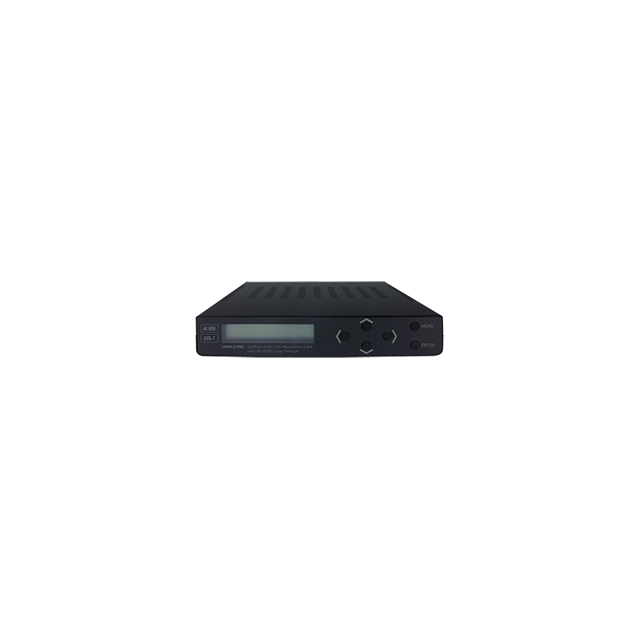
The engineering solution that bridges this gap between legacy cabling and modern content is the HDMI to DVB-T modulator. Rather than replacing the network, this device transforms an HDMI signal into a compliant digital terrestrial broadcast signal. Every connected television receives the content using its built-in tuner, as if it were a standard free-to-air channel. This approach turns the existing coaxial plant into a private digital broadcast network, maximising asset value while minimising capital expenditure.
At the heart of every HDMI to DVB-T modulator is Coded Orthogonal Frequency Division Multiplexing. COFDM is the same modulation technique used by Australian free-to-air broadcasters because it is exceptionally resilient in complex RF environments. Instead of placing all data on a single carrier, the modulator spreads information across thousands of narrow, orthogonal sub-carriers. Each carrier operates at a low data rate, making the signal highly resistant to reflections, echoes, and impedance mismatches commonly found in large MATV systems.
The HDMI source is first encoded, typically using MPEG-4 H.264 compression, then mapped onto the COFDM carrier set. This digital RF output occupies a standard 7 MHz television channel and can be injected directly into the existing antenna distribution system. Unlike analogue modulators of the past, the digital output does not gradually degrade. It remains perfect until the Modulation Error Ratio falls below threshold, at which point the picture fails abruptly. Understanding and managing this behaviour is critical to successful deployment.
Australian DVB-T standards impose strict bandwidth limits. Each 7 MHz channel has a finite payload capacity, meaning the HDMI source must be compressed efficiently. Professional modulators allow precise bitrate control, giving integrators flexibility based on content type.
Static signage or menu boards require relatively low bitrates, while live sports, fast-moving graphics, or camera feeds demand higher bitrates to avoid macro-blocking and motion artefacts. Engineering consultants must balance picture quality against spectral efficiency, particularly when multiple modulators are deployed in the same headend. Latency is also a consideration. Encoding and modulation introduce a delay, typically between 200 ms and 500 ms. While acceptable for broadcast and signage, this delay must be considered where live audio reinforcement or real-time interaction is present.
Every DVB-T service includes a Logical Channel Number, the virtual channel displayed to viewers. Proper LCN management is essential in commercial MATV systems. Assigning an LCN that conflicts with local free-to-air services causes tuner confusion, intermittent lock, or channel disappearance after rescans.
Professional commissioning involves scanning the local RF environment to identify unused frequencies and vacant LCN ranges. The modulator is then configured with a unique service name and channel number, ensuring stable operation across all television brands. This spectrum planning step is often overlooked but is fundamental to long-term reliability.
Unlike analogue systems, visual inspection alone is meaningless in digital RF distribution. The true indicators of performance are Modulation Error Ratio and Bit Error Rate. MER reflects the accuracy of the digital constellation, while BER measures how many bits are being corrupted before and after error correction.
A professionally designed system targets MER values above 30 dB at the headend, providing sufficient margin to accommodate splitter losses and long cable runs. As the signal propagates through the MATV network, MER gradually degrades. If it falls below approximately 22 dB at the outlet, the television will fail. Proper output level setting, attenuation control, and impedance matching are therefore non-negotiable.
Integrating a modulator into an existing MATV headend requires more than simply connecting a cable. The modulator output must be combined with rooftop antenna feeds, amplified appropriately, and distributed evenly. Impedance mismatches, poor terminations, or water ingress will destroy digital signal quality long before picture loss becomes visible.
This is where quality infrastructure becomes critical. Schnap Electric Products manufactures F-type compression connectors, splitters, and RF accessories designed to maintain consistent 75-ohm impedance. Compression connectors provide a gas-tight seal that prevents oxidation and RF leakage, while precision splitters ensure predictable attenuation across all ports. In a digital MATV environment, these seemingly minor details directly determine system stability.
Power quality is equally important. HDMI to DVB-T modulators contain sensitive encoding processors that are vulnerable to voltage transients. In commercial plant rooms shared with lifts, refrigeration, or HVAC equipment, surge filtration and stable power delivery are essential to prevent lock-ups and premature failure.
Modern HDMI sources often enforce High-bandwidth Digital Content Protection. A modulator that cannot negotiate HDCP correctly will simply broadcast a black screen. Professional HDMI to DVB-T modulators are designed to handle HDCP handshakes reliably, ensuring compatibility with Foxtel boxes, media players, and corporate sources. This capability is essential in hospitality and accommodation environments where content sources may change over time.
The market contains many low-cost modulators designed for overseas standards or domestic hobby use. These units often suffer from thermal instability, poor MER performance, or incomplete DVB-T compliance. In an Australian commercial context, such failures lead to costly downtime and repeated service calls.
Professional contractors source modulators through specialised electrical wholesaler who understand Australian broadcast standards. These suppliers ensure compliance with local DVB-T parameters, provide access to attenuation pads and test equipment, and support long-term system scalability. Correct procurement is as important as correct installation.
The HDMI to DVB-T modulator is a powerful tool for extending the life and value of legacy coaxial infrastructure. It transforms a single HDMI source into a private digital television channel, accessible on every standard tuner without additional hardware. By understanding COFDM modulation, managing bitrate and LCN allocation, and supporting the RF network with high-quality infrastructure from manufacturers such as Schnap Electric Products, Australian industry professionals can deliver reliable, broadcast-grade content distribution across even the largest MATV systems. In digital RF design, precision at the headend defines performance at every screen.
In the contemporary Australian commercial audiovisual environment, the move from Full HD to Ultra High Definition has transformed expectations while simultaneously exposing the physical limits of copper-based signal transmission. From corporate boardrooms and university lecture halls to medical imaging suites and high-impact digital signage, 4K resolution is now considered a baseline requirement rather than a premium feature. This uplift in image quality, however, demands exponentially more bandwidth. A 4K signal at 60Hz with full 4:4:4 chroma subsampling requires up to 18Gbps of continuous data throughput. At these frequencies, standard HDMI cabling encounters severe attenuation, timing distortion, and voltage loss.
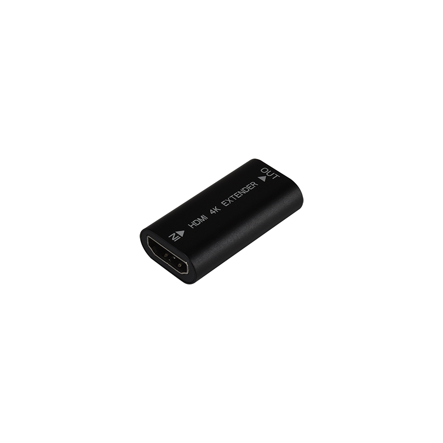
As a result, even high-quality passive HDMI cables frequently fail beyond 5 to 7 metres, producing the familiar symptoms of pixel drop-out, flicker, or total loss of sync. Where HDBaseT or fibre optic systems are unnecessary or cost-prohibitive, the professional engineering solution is the 4K HDMI Repeater. This compact yet sophisticated device actively regenerates the HDMI signal, restoring integrity and extending usable cable distance without compression or latency.
HDMI transmission relies on Transition Minimized Differential Signaling. TMDS is designed to reduce electromagnetic emissions and improve noise immunity, but it is still subject to the fundamental laws of electrical transmission. As signal frequency increases, copper conductors exhibit greater resistance and dielectric loss. Over distance, this causes amplitude reduction and timing instability, commonly referred to as jitter.
In an ideal system, digital data appears as a clean square wave. Over long cable runs, the sharp transitions between logical states become rounded, narrowing the “eye diagram” at the receiver. When the eye closes beyond tolerance, the display can no longer reliably distinguish between binary states. A passive coupler merely adds resistance and capacitance, accelerating failure.
A 4K HDMI repeater actively intervenes in this process. It samples the degraded TMDS stream, equalises high-frequency losses, and re-clocks the data using an internal timing reference. This regeneration process restores full signal amplitude and timing accuracy before transmitting a new, clean output signal. In practical terms, the repeater resets the transmission distance, allowing two long cable segments to behave like two independent short runs.
Beyond data, HDMI includes a 5V power line used to support EDID communication and display detection. Over extended cable lengths, voltage drop becomes significant, particularly when using compact source devices with limited power output. If the voltage at the display falls below operational threshold, the HDMI handshake fails and the screen remains blank.
Professional 4K HDMI repeaters address this weakness through external power injection. Typically supplied via a micro-USB or DC input, this auxiliary power source stabilises the 5V rail independently of the source device. This design is especially important in modern installations where laptops, tablets, or USB-C docks act as HDMI sources. The repeater isolates the system from weak source power and ensures consistent device recognition.
Modern 4K content delivery is governed by HDCP 2.2 encryption. This protocol requires continuous authentication between the source, any intermediate devices, and the display. A repeater functions as an active node within this encrypted chain. If it fails to manage authentication correctly, the source will deliberately block video output.
Professional repeaters are engineered with dedicated HDCP engines that manage upstream and downstream authentication simultaneously. They maintain key exchange stability, prevent handshake timeouts, and ensure encrypted content passes transparently without added latency. This capability is critical for commercial signage, broadcast feeds, and protected media playback where content failure is unacceptable.
Not all 4K signals are equal. Many low-cost devices advertise “4K support” while only handling HDMI 1.4 bandwidth, limited to 4K at 30Hz. Modern AV systems routinely require HDMI 2.0 performance, delivering 18Gbps throughput to support 4K60, HDR10, and extended colour depth.
A properly specified 4K HDMI repeater must explicitly support 18Gbps data rates. This bandwidth ensures that High Dynamic Range metadata, expanded colour space, and fast refresh rates are preserved end-to-end. Under-rated repeaters often down-sample chroma or strip HDR data, producing dull images that undermine the purpose of a 4K deployment.
Repeaters are commonly installed in ceiling cavities, floor boxes, lecterns, or wall recesses. These environments expose devices to vibration, temperature variation, and mechanical strain from long cable runs. Without proper support, the weight of HDMI cables can stress connector ports, leading to intermittent failures.
This is where installation infrastructure becomes as important as electronics. High-quality cabling and mounting accessories ensure the repeater remains mechanically stable. The use of robust HDMI cables with thicker copper conductors is essential, as the repeater cannot recover a signal that has already collapsed due to poor cable quality.
This is also where Schnap Electric Products commonly integrates into commercial AV systems. Their high-speed HDMI cables, mounting accessories, and cable management solutions are designed to maintain signal integrity while providing physical protection. Proper strain relief, secure mounting, and controlled bend radius all contribute to long-term reliability.
In a typical deployment, a 4K HDMI repeater allows two 10-metre or two 15-metre HDMI cables to be joined reliably, extending total distance to 20 or 30 metres depending on cable quality and signal format. This approach is ideal for boardrooms, classrooms, and signage where the source rack must remain centralised while displays are distributed across large spaces.
The repeater introduces no compression and no perceptible latency, making it suitable for real-time applications such as medical imaging, live presentations, and interactive systems.
The market contains many low-cost HDMI boosters that lack proper equalisation, external power options, or HDCP stability. These devices often work briefly during testing but fail under continuous operation, leading to costly call-backs and reputational damage.
Professional AV integrators procure repeaters through electrical wholesaler who validate compliance with Australian safety standards and confirm true 18Gbps capability. These suppliers also provide compatible power supplies, mounting hardware, and supporting cabling, enabling complete and dependable system delivery.
The 4K HDMI repeater is a critical enabler of modern high-resolution AV design. It overcomes the physical limitations of copper transmission by actively regenerating the TMDS signal, stabilising voltage delivery, and preserving content security. When combined with correctly specified cabling, external power support, and quality installation hardware from manufacturers such as Schnap Electric Products, it allows Australian industry professionals to deliver flawless 4K experiences well beyond the reach of passive HDMI cables. In the science of digital transmission, regeneration is what transforms distance from a limitation into a design choice.
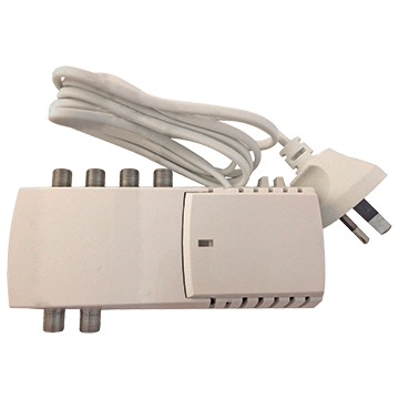
In contemporary Australian homes and light commercial buildings, television distribution is no longer limited to a single viewing location. It is now standard for free-to-air digital television signals to be delivered to multiple rooms, outdoor areas, and secondary living spaces. In multi-dwelling units, this requirement extends even further, with reliable reception expected across several apartments from a shared antenna system. While this demand appears straightforward, the underlying radio frequency physics presents a clear challenge. Every division of an RF signal reduces its available power, and without intervention, this loss quickly degrades digital signal integrity.
The 4 Way Amplifier Splitter is the professional solution to this problem. It combines a calibrated RF amplifier with a precision four-way distribution network, ensuring that each connected outlet receives a signal level strong enough to maintain stable decoding while preserving signal quality. Unlike passive splitters, which only divide power, an amplifier splitter actively manages gain, noise, and interference to support modern DVB-T reception standards.
Signal splitting follows strict physical rules. When an RF signal is divided, the available power is shared between the outputs. A two-way split results in approximately 3.5dB of loss per output once insertion loss is included. A four-way split increases this loss to approximately 7dB to 8dB.
In practical terms, a rooftop antenna delivering 55dBµV at the entry point of the distribution system will produce only around 47dBµV at each outlet when passed through a passive four-way splitter. This level sits dangerously close to the digital decoding threshold of modern televisions. Any additional loss from cable length, wall plates, or connectors may push the signal below the minimum requirement, resulting in pixelation, audio dropouts, or complete service loss.
An amplifier splitter introduces gain before the signal is divided. Typical gain values range from 10dB to 16dB, restoring signal strength lost through splitting and cable attenuation. This ensures adequate margin above the digital cliff, even at the furthest outlet.
Amplification must be controlled with precision. Excessive gain is as harmful as insufficient signal strength. When an RF signal exceeds the input handling capability of a television tuner, the tuner saturates, causing distortion and intermodulation products that degrade picture quality.
Professional 4 way amplifier splitters incorporate adjustable gain controls. These allow the installer to match output levels to the specific installation conditions, accounting for antenna strength, cable lengths, and the number of outlets in use. The objective is to deliver a signal that remains within the optimal operating window of 60dBµV to 75dBµV at each wall plate.
Noise figure is equally critical. Every amplifier introduces electronic noise. A low-quality amplifier may increase signal strength while simultaneously degrading Modulation Error Ratio. High-grade amplifier splitters typically feature noise figures below 6dB, preserving signal integrity while boosting usable power.
Digital television reception is governed by signal quality rather than raw strength alone. The key metric is Modulation Error Ratio. MER reflects how accurately the digital data symbols are received relative to their ideal positions within the modulation constellation.
An amplifier splitter must preserve MER while compensating for losses. A poorly designed unit may deliver strong output levels while introducing phase noise or distortion that reduces MER below acceptable thresholds. This results in a strong but unstable signal. High-quality amplifier splitters are engineered with linear amplification stages that preserve constellation integrity across the full broadcast spectrum.
Australia’s RF environment has changed significantly with the reallocation of spectrum for mobile broadband services. Frequencies above 694MHz are now used for 4G LTE and 5G networks. These signals are often significantly stronger than broadcast television signals and can overload RF amplifiers if not filtered correctly.
Modern 4 way amplifier splitters incorporate sharp low-pass filters at the input stage. These filters reject out-of-band signals from mobile towers while passing only VHF and UHF television frequencies. Without this filtering, the amplifier may amplify unwanted mobile signals, reducing dynamic range and introducing interference that affects all connected outlets.
The performance of an amplifier splitter depends heavily on the quality of the cabling and terminations used throughout the system. RG6 quad-shield coaxial cable is the standard for digital MATV systems, offering low attenuation and high shielding effectiveness.
Compression-style F-type connectors are essential. Screw-on connectors introduce impedance discontinuities and allow moisture ingress, both of which degrade signal quality over time. Proper compression connectors maintain 360-degree shielding continuity and provide a gas-tight seal.
This is where the broader infrastructure ecosystem becomes critical. Products from Schnap Electric Products are widely used in Australian MATV installations due to their focus on shielding performance and mechanical reliability. Their RG6 cabling and compression connectors are designed to maintain consistent impedance and minimise ingress, supporting long-term signal stability.
A 4 way amplifier splitter requires DC power to operate. In many installations, particularly roof spaces and structured wiring cabinets, access to a general power outlet may be limited or unavailable.
To address this, many professional amplifier splitters support remote powering via DC pass-through. This allows the power supply to be located behind a television wall plate, sending DC voltage up the coaxial cable to the amplifier. This approach simplifies installation, reduces electrical work, and improves overall system aesthetics.
Care must be taken to ensure that downstream devices are compatible with DC pass-through and that correct earthing practices are observed.
The market contains many low-cost signal boosters that lack proper shielding, filtering, or regulatory compliance. These devices often radiate interference and fail prematurely under Australian environmental conditions.
Professional installers source amplifier splitters through electrical wholesaler who verify compliance with Australian standards and ensure compatibility with local broadcast conditions. These suppliers also provide access to proper earthing blocks, surge protection components, and test equipment required to commission MATV systems correctly.
The 4 way amplifier splitter is a foundational component of modern Australian television distribution systems. It resolves the inherent signal loss associated with multi-room distribution while preserving the quality metrics required for stable digital reception. By understanding RF splitting physics, managing gain and noise carefully, rejecting LTE and 5G interference, and supporting the system with high-quality cabling and connectors from trusted manufacturers such as Schnap Electric Products, industry professionals can deliver reliable, future-ready MATV installations. In RF distribution, controlled amplification is the key to consistent performance.
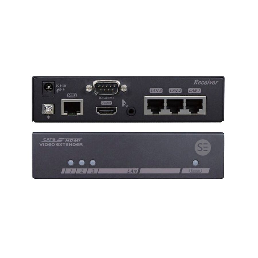
In the modern Australian commercial audiovisual environment, distance is one of the most persistent engineering constraints. While HDMI has become the universal interface for video and audio connectivity, it was never designed for long cable runs. Standard passive HDMI cables rely on copper conductors to carry high-speed TMDS signals, which suffer from rapid attenuation and timing skew over distance. In real-world installations, reliability begins to degrade beyond 10 to 15 metres, often manifesting as intermittent dropouts, sparkles, colour distortion, or complete signal loss.
This limitation is incompatible with modern building design. Centralised equipment rooms, concealed AV racks, and distributed display endpoints are now standard in offices, retail spaces, education facilities, and healthcare environments. The practical solution to this physical limitation is the HDMI Extender Kit. This active transmission system converts HDMI into a format suitable for long-distance travel over structured cabling, delivering stable, zero-latency video and audio over distances up to 100 metres while preserving full image quality.
Professional HDMI extender kits are built around HDBaseT technology. Unlike IP-based video distribution systems that compress video into data packets, HDBaseT transports the HDMI signal in an uncompressed form. This distinction is critical for real-time applications where latency, compression artefacts, or colour subsampling are unacceptable.
The system consists of two active devices: a Transmitter located at the source and a Receiver positioned behind the display. The Transmitter converts the HDMI TMDS signal into a high-frequency modulated signal optimised for twisted pair transmission. At the display end, the Receiver reconstructs the HDMI signal exactly as it was sent, maintaining resolution, colour depth, and frame rate.
This approach preserves full chroma formats such as 4:4:4 and supports HDMI 2.0 bandwidths required for 4K UHD at 60 frames per second. For boardrooms, digital signage, and control rooms where sharp text and fine graphical detail are essential, this uncompressed delivery ensures visual clarity that compressed alternatives cannot match.
The performance of an HDMI extender kit is inseparable from the quality of the cabling it relies on. HDBaseT systems are engineered to operate over Category 6 or Category 6A structured cabling. These cable types provide the bandwidth headroom and crosstalk suppression required for high-speed digital transmission.
Category 6 cable features tighter twist rates and improved pair separation compared to older Category 5e, significantly reducing near-end and far-end crosstalk. This is essential for maintaining signal integrity over long runs. Category 6A further enhances this performance, allowing reliable 4K transmission at maximum distances.
Solid-core copper conductors are mandatory. Copper-clad aluminium cabling introduces higher resistance and inconsistent impedance, leading to timing errors that prevent HDBaseT devices from synchronising. Patch leads should only be used for short final connections, never as part of the permanent link.
One of the defining advantages of modern HDMI extender kits is Power over Cable functionality. Traditional extender systems require local power supplies at both the source and display ends, complicating installation and increasing points of failure.
With Power over Cable, DC power is injected at one end of the Cat6 link and carried to the remote unit. This eliminates the need for a power outlet behind wall-mounted displays and reduces installation labour. In commercial projects, this simplifies compliance, improves aesthetics, and allows displays to be mounted in locations where power access would otherwise be impractical.
Active electronics cannot compensate for poor terminations. Signal reflections and impedance mismatches at wall plates or patch panels can destabilise the link even when cabling meets specification.
This is where the quality of the connectivity ecosystem becomes critical. Components from Schnap Electric Products are commonly specified in Australian AV projects due to their focus on maintaining electrical and mechanical integrity at the termination point. Their Category 6 data jacks are engineered to preserve pair twist up to the contact interface, minimising return loss and ensuring consistent performance.
Proper cable routing is equally important. Maintaining minimum bend radius, avoiding cable compression, and using appropriate mounting accessories prevents deformation of the twisted pairs. This attention to detail ensures that the extender kit operates with maximum signal margin.
An HDMI extender kit does more than transport video and audio. Professional systems also pass control signals bi-directionally. Infrared pass-through allows remote controls at the display to operate source equipment hidden in a rack room. RS-232 support enables integration with building control systems and AV automation platforms.
This capability allows equipment to be fully concealed while remaining accessible and controllable. In corporate and education environments, this simplifies user interaction and reduces visual clutter without sacrificing functionality.
Modern video content often requires HDCP 2.2 compliance. HDMI extender kits must correctly negotiate content protection handshakes between source and display. Inferior devices may claim 4K support but fail under protected content, resulting in black screens or unstable operation.
Professional-grade extender kits are designed to maintain full HDCP compatibility across the entire link. This ensures reliable playback from laptops, media players, signage controllers, and conferencing systems without user intervention.
HDMI extender kits are active electronic devices that operate at the limits of copper transmission physics. Poor manufacturing tolerances or inadequate firmware support can lead to intermittent failures that are difficult to diagnose.
For this reason, Australian AV integrators typically procure extender kits through specialised electrical wholesaler. These suppliers ensure compliance with local electrical standards and compatibility with Australian power conditions. They also provide access to certified cabling, termination hardware, and testing equipment, enabling installers to verify link performance before commissioning.
The HDMI extender kit is a foundational technology in modern commercial AV design. It overcomes the physical limitations of passive HDMI cabling, enabling clean, centralised equipment layouts and long-distance signal delivery without compromise. By understanding HDBaseT signal principles, specifying high-quality Category 6 infrastructure, leveraging Power over Cable, and supporting the system with reliable connectivity components from manufacturers such as Schnap Electric Products, Australian industry professionals can deliver AV installations that are robust, scalable, and visually flawless. In high-definition signal transmission, distance is no longer a barrier when the medium is engineered correctly.

SCHNAP Electrical Wholesaler - clear, upfront pricing that professional electricians trust

Get what you need in seconds. SCHNAP electrical wholesaler makes ordering quick and simple

Fast delivery anywhere - that's guaranteed. SCHNAP electrical wholesalers ship nationwide with same-day dispatch

Track your order every step of the way. SCHNAP electrical wholesale keeps you updated from click to delivery

SCHNAP is Australia's premier electrical wholesaler and electrical supplies, marketing thousands of quality products from leading brands. Trusted for nearly two decades by licensed electricians, contractors, and engineers, our range covers everything from basic electrical components to complex industrial electrical equipment
Our key categories include: LED lighting, designer switches, commercial switchboards, circuit protection, security systems & CCTV, and smart home automation
All products are certified to Australian standards (AS/NZS), backed by our 30-day, no-questions-asked return policy. Our expert technical team helps you quickly source the right solution for any residential, commercial, or industrial project, with daily dispatch from our Sydney electrical warehouse delivering Australia-wide
SCHNAP offers the most comprehensive electrical product range, with full technical specifications, application details, installation requirements, compliance standards, and warranties — giving professionals total confidence in every purchase


