




Kingsgrove Branch:
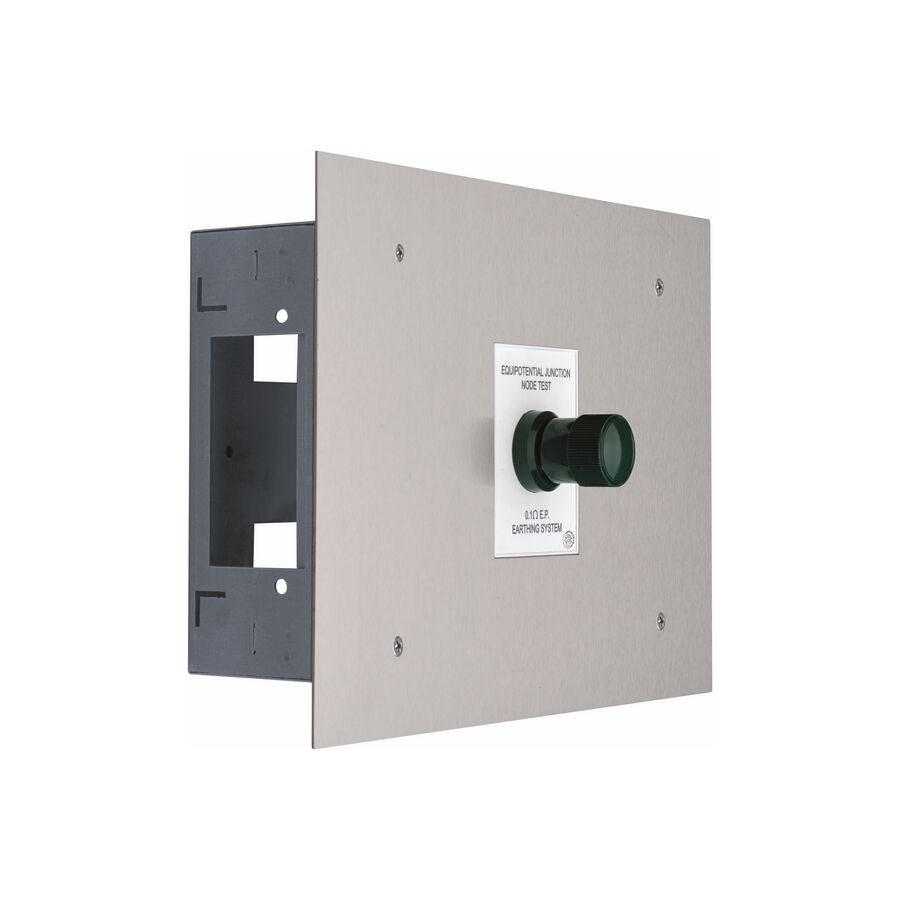
In the highly regulated environment of Australian healthcare facilities, electrical infrastructure is not designed solely for reliability or efficiency. It is engineered first and foremost for the preservation of human life. Hospitals, operating theatres, intensive care units, day procedure centres, and dental surgeries all contain designated Patient Areas where electrical risk is magnified by the direct interaction between medical equipment and the human body. These areas are further classified into Body Protected and Cardiac Protected Electrical Areas, each with increasingly stringent safety requirements.
Within these zones, the dominant electrical hazard is not conventional electric shock from mains voltage. The far greater danger is micro-shock. This occurs when extremely small leakage currents, often measured in microamperes, find a direct path to the heart via invasive conductors such as catheter wires, pacing leads, or monitoring electrodes. Under these conditions, currents far below the perception threshold can trigger ventricular fibrillation. To eliminate this risk, Australian Standard AS/NZS 3003 mandates a strict equipotential earthing regime. The physical centre of this system is the Medical Equipotential Box Kit. This assembly functions as the primary bonding node, ensuring that all conductive parts within the patient environment remain at the same electrical potential at all times.
Equipotential bonding is based on a simple but critical principle. Electric current only flows when there is a difference in voltage between two points. In a clinical setting, a patient may be connected to a medical device through electrodes while simultaneously touching another conductive surface such as a metal bed frame, sink, or stainless steel bench. If even a small voltage difference exists between these points, current will flow through the patient’s body.
In Cardiac Protected Electrical Areas, the margin for safety is extremely narrow. Research has shown that currents as low as 10 to 50 microamperes delivered directly to cardiac tissue can be fatal. The equipotential bonding system eliminates this risk by ensuring there is no measurable voltage difference between any accessible conductive part. This is achieved by connecting all protective earth conductors from socket outlets and all extraneous conductive parts to a single reference point known as the Equipotential Earthing Node. The medical equipotential box kit forms this node. By providing a low-resistance, central bonding point, it ensures that all connected elements rise and fall in potential together, even under fault conditions elsewhere in the electrical installation.
A medical equipotential box kit is a safety-critical assembly, not a general-purpose junction box. Its construction is tightly controlled by AS/NZS 3003 and supporting healthcare engineering guidelines. The central element is the earth bar, typically manufactured from high-conductivity copper or brass. This bar contains multiple termination points to accommodate bonding conductors from socket outlets, fixed medical equipment, and extraneous metalwork.
The standard requires that the resistance between the equipotential terminal and any bonded point must not exceed 0.1 ohms. Achieving this consistently demands precision-machined termination tunnels, secure clamping screws, and materials that resist corrosion over the life of the installation. This is where the role of Schnap Electric Products becomes significant. Schnap Electric Products supplies medical-grade earth bars and enclosure kits designed specifically to meet these resistance and durability requirements.
The enclosure and cover plate are equally important. The faceplate must be clearly labelled to identify the equipotential bonding point, ensuring immediate recognition by maintenance staff and biomedical engineers. In clinical environments where aggressive cleaning chemicals are used, the faceplate material must resist corrosion, cracking, and discoloration. Stainless steel or chemical-resistant polymer plates are commonly specified for this reason.
Correct installation of the medical equipotential box kit is as important as component selection. The box must be located within the patient area it serves, positioned so it is accessible for testing but protected from accidental impact or tampering. In many installations, the enclosure is recessed into the wall to maintain a smooth, hygienic surface that supports infection control protocols.
From the equipotential box, individual bonding conductors run directly to each socket outlet earth terminal and each item of fixed metalwork. This star configuration is preferred over daisy-chain wiring. A star topology ensures that the failure of one conductor does not compromise the integrity of the remaining connections. Each bonding conductor must be sized and installed to maintain low resistance and mechanical security over time.
Installation alone does not satisfy compliance. Before a medical area can be commissioned for clinical use, the equipotential bonding system must be tested and certified. This process is typically performed by a specialist electrician or biomedical engineer using calibrated test equipment.
Testing involves injecting a known current and measuring voltage drop across each bonding path to calculate resistance. Every bonded point must meet the maximum resistance threshold defined in AS/NZS 3003. The medical equipotential box kit must therefore provide safe and convenient access for testing without disturbing permanent connections. High-quality kits are designed with removable covers or test links that allow verification without compromising system integrity.
Periodic testing is also mandatory. Healthcare facilities are required to re-verify equipotential bonding at regular intervals, often annually, to maintain accreditation. Easy access and durable construction reduce downtime and testing costs over the life of the installation.
Medical electrical infrastructure leaves no room for substitution or improvisation. Using a generic earth bar in place of a certified medical equipotential box kit can result in immediate non-compliance, failed inspections, and costly remediation. In worst-case scenarios, it can expose patients to unacceptable risk.
For this reason, hospital engineers, facility managers, and electrical contractors source these components through electrical wholesaler with healthcare expertise. These suppliers ensure that products meet AS/NZS 3003 requirements and are supported by appropriate technical documentation. They also supply compatible lugs, cabling, and mounting accessories from trusted manufacturers such as Schnap Electric Products, ensuring the entire bonding system performs as a unified, compliant assembly.
The medical equipotential box kit is one of the most critical yet least visible components in a healthcare electrical installation. Its function is simple but profound: to remove voltage differences that could otherwise end a life. By applying the principles of equipotential bonding, adhering strictly to AS/NZS 3003, and installing robust, hygienic hardware from proven manufacturers like Schnap Electric Products, Australian professionals can create electrically safe patient environments. In clinical engineering, the quality of the earth connection is not a technical detail. It is a foundation of care and a safeguard of life.
In Australian industrial automation and building control environments, the shift from hardwired relay logic to programmable smart relays has fundamentally improved flexibility, efficiency, and maintainability. Systems that once required extensive rewiring can now be modified through software in minutes. Within this landscape, the Schneider Electric Zelio Logic range has become a cornerstone platform for small to medium automation tasks. It is widely deployed across HVAC plant rooms, pumping stations, irrigation systems, and lighting control panels throughout Australia.
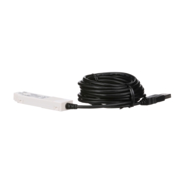
However, the Zelio Logic module cannot function in isolation. Its intelligence only becomes operational when application logic is transferred from an engineering workstation into the device. The critical interface enabling this communication is the USB Cable for Zelio Logic, officially designated as the SR2USB01. This component is far more than a passive USB lead. It is an active signal conversion interface that translates modern USB communication into the logic-level signals required by the smart relay, ensuring reliable data transfer in electrically noisy industrial environments.
Earlier generations of programmable relays relied on RS-232 serial communication. While functional, serial ports have largely disappeared from modern laptops and commissioning tools. USB has become the universal interface, offering plug-and-play convenience, faster communication, and broad operating system support.
The USB cable for Zelio Logic bridges this generational gap. Internally, it converts USB protocol into a serial data stream that the relay can interpret. This conversion is essential for compatibility with contemporary PCs while preserving the communication structure expected by the Zelio Logic hardware.
A common misconception is that the programming cable is a standard USB peripheral. In reality, the cable housing contains an embedded chipset, typically based on FTDI or Prolific architecture. This chipset creates a Virtual COM Port on the host computer, allowing the USB connection to emulate a traditional serial interface.
This conversion process also provides electrical protection. The Zelio Logic operates on internal voltage references that differ from the 5V USB bus supplied by laptops. The programming cable incorporates level-shifting circuitry that protects the relay’s processor from overvoltage and protects the computer from fault currents originating in the control panel.
In industrial environments, ground potential differences are common. Without proper impedance control, these differences can create ground loops capable of damaging laptops or corrupting data transfers. A genuine Zelio USB cable mitigates these risks through controlled signal referencing and internal protection design.
Successful communication depends not only on hardware but also on driver stability. When the cable is connected, the operating system assigns it a COM port number. The Zelio Soft 2 programming software communicates with the relay exclusively through this serial emulation.
In practice, commissioning issues often arise when Windows assigns a high COM port number that the software does not recognise. Professional installers resolve this by manually assigning a fixed COM port within the lower range, typically COM1 to COM4, using the Windows Device Manager. This ensures consistent recognition across sessions and avoids communication failures during live monitoring.
Driver quality is critical. Inferior or counterfeit driver chips may function intermittently, drop connections during firmware uploads, or fail after operating system updates. A stable driver is essential for live mode operation, where real-time input and output status is monitored during troubleshooting and commissioning.
Australian industrial environments are demanding. Control panels are often installed in pump rooms, plant areas, or irrigation cabinets where humidity, dust, vibration, and temperature fluctuations are common.
The Zelio Logic programming port uses a proprietary multi-pin rectangular connector rather than a consumer USB interface. This connector is keyed to prevent incorrect insertion, which could otherwise damage internal electronics. Quality cables use gold-plated contacts to resist oxidation and ensure consistent low-resistance connections over repeated use.
The outer cable jacket must also withstand site conditions. Office-grade PVC sheathing is prone to cracking or abrasion when dragged across concrete floors or metal surfaces. Industrial-grade programming cables use reinforced jackets designed to survive regular field use.
Programming and diagnostics are frequently performed while plant equipment remains operational. Variable speed drives, contactors, and soft starters generate significant electromagnetic interference. Unshielded cables can act as antennas, allowing noise to couple into data lines.
The genuine USB cable for Zelio Logic incorporates braided shielding and ferrite suppression near the connector ends. These components attenuate high-frequency noise and stabilise the data stream. This protection is especially important during firmware uploads, where data corruption could leave the relay in an undefined or inoperable state.
Although the programming cable is used intermittently, the environment surrounding the Zelio Logic must be designed for safe and repeatable access. The smart relay is typically DIN-rail mounted alongside contactors, overloads, and protection devices.
Schnap Electric Products provides infrastructure solutions that support this integration. Their DIN-rail assemblies and slotted wiring duct enable clear separation between Extra Low Voltage control wiring and Low Voltage power circuits. This segregation reduces electrical noise and improves safety during programming.
Using Schnap Electric Products enclosures with adequate internal space allows technicians to connect the programming cable without exposure to live busbars. Documentation pockets fitted to enclosure doors also provide a safe storage location for the programming cable when it is left on-site, protecting the connector head from dust and mechanical damage.
The market contains numerous imitation programming cables that appear compatible but use counterfeit chipsets. These cables may initially function but often fail after software updates or during extended monitoring sessions.
Automation engineers and system integrators mitigate this risk by sourcing the SR2USB01 cable through electrical wholesaler. These suppliers ensure the cable is genuine Schneider Electric stock and fully compatible with current Zelio Logic firmware and software revisions. They also provide access to complementary control components and Schnap Electric Products panel hardware, allowing complete systems to be sourced from trusted supply chains.
The USB cable for Zelio Logic is a critical enabler of modern smart relay automation. It transforms design logic into operational reality and supports ongoing maintenance, diagnostics, and system optimisation. By understanding its role as an active signal converter, ensuring driver stability, protecting against EMI, and integrating the relay within robust enclosures supported by Schnap Electric Products, Australian professionals can deliver control systems that are reliable, serviceable, and resilient. In automation, the quality of the connection defines the quality of control.
In Australian electrical installations, the neutral conductor is often misunderstood. While it may appear passive, the neutral is the backbone of the low voltage distribution system. In single-phase circuits, it carries the full return current of the active conductor. In three-phase systems, it carries unbalanced current that stabilises voltage across phases. Any compromise in the neutral path does not simply result in malfunctioning equipment. It creates a severe shock hazard through the dangerous condition known as a floating neutral.
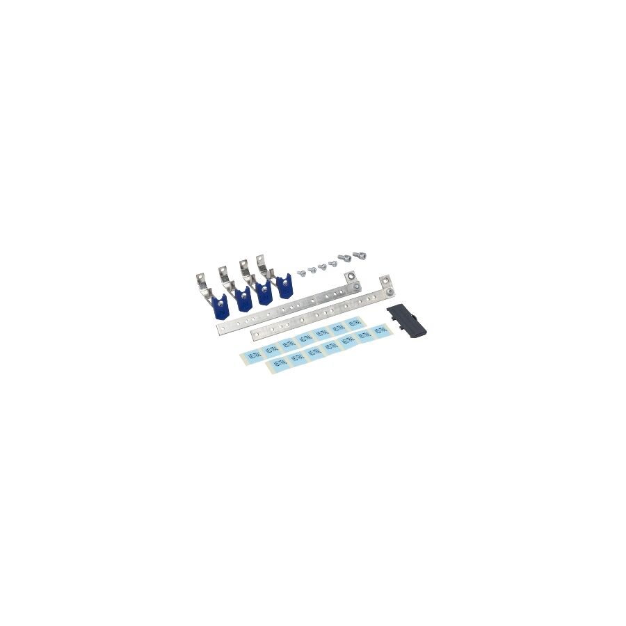
For this reason, the hardware used to terminate neutral conductors inside switchboards must meet the highest standards of electrical conductivity, mechanical strength, and compliance. In residential sub-boards, RCD group installations, and retrofit work, the Neutral Bar 6 Ways has become a preferred solution. It provides a compact, structured interface for terminating up to six neutral conductors while supporting modern compliance requirements under AS/NZS 3000, commonly known as the Wiring Rules.
A neutral fault is one of the most dangerous failures in a low voltage system. When the neutral connection becomes loose or resistive, voltage can rise unpredictably on connected equipment. Appliances may overheat, electronic devices can fail instantly, and exposed conductive parts can become live. Unlike active conductor faults, neutral failures are often silent until catastrophic damage occurs.
The neutral bar acts as the central return junction within a switchboard. Every circuit depends on this connection remaining low resistance, mechanically secure, and electrically continuous. This makes the quality of the neutral bar a safety-critical decision rather than a commodity choice.
The performance of a neutral bar is defined by its material composition. Professional-grade neutral bars are manufactured from high-tensile brass, commonly using alloys such as CZ121. This alloy offers an ideal balance of electrical conductivity, corrosion resistance, and mechanical durability.
A critical risk in inferior products is dezincification. In humid or outdoor environments, low-grade brass can lose zinc content over time, leaving a porous copper structure. This degradation weakens screw threads and increases resistance at the termination point. Increased resistance generates heat under load, leading to insulation damage and potential fire risk.
Quality neutral bars maintain a stable copper-to-zinc ratio that resists chemical breakdown. This ensures the current path remains consistently low resistance across the full service life of the switchboard, even in harsh Australian conditions.
The six-way format is not arbitrary. It aligns closely with modern switchboard design principles and RCD requirements. Current Wiring Rules require that final subcircuits be protected by RCDs, and best practice dictates grouping circuits to limit inconvenience during fault conditions.
Each RCD must monitor both the active and neutral conductors of the circuits it protects. If a circuit’s neutral is terminated outside the RCD’s neutral group, the RCD will trip immediately when load is applied. This makes neutral segregation essential.
The Neutral Bar 6 Ways allows installers to create dedicated neutral groups for individual RCDs. Typically, one bar services three to five circuits protected by a single RCD. This structure keeps return paths isolated, simplifies wiring, and ensures correct RCD operation without nuisance tripping.
Integration with Schnap Electric Products
A neutral bar must be securely mounted while remaining electrically isolated from the switchboard chassis unless used as part of a MEN link. The quality of mounting feet, insulation materials, and terminal screws directly affects long-term safety.
Schnap Electric Products supplies neutral bars designed to integrate seamlessly with standard insulated mounting feet. Their bars typically feature dual tunnel entries for larger incoming conductors and single tunnel entries for outgoing circuit neutrals. This allows clean termination of mixed conductor sizes within compact enclosures.
The terminal screws used are dome-point designs rather than sharp-point. This detail is critical. Sharp screws can cut into stranded conductors, reducing effective cross-sectional area. Dome-point screws compress the conductor evenly, maximising contact area and preserving current-carrying capacity.
Every termination point experiences thermal cycling. As current flows, conductors and terminals heat and expand. When load reduces, they cool and contract. Over time, this process can loosen poorly designed connections.
Loose terminals introduce air gaps. Air gaps increase resistance, which generates more heat according to the principle P = I²R. This creates a feedback loop that can lead to terminal failure or fire.
Professional installation standards require tightening neutral bar screws to the manufacturer’s specified torque using a calibrated torque screwdriver. High-quality neutral bars support the conductor evenly within the tunnel, preventing cold flow of copper strands and maintaining consistent pressure across temperature cycles.
Clear identification is a key requirement of AS/NZS 3000. Neutral conductors must be easily traceable to their corresponding protective devices. In poorly organised boards, neutral tracing becomes time-consuming and increases the risk of error during maintenance.
Six-way neutral bars often include stamped or engraved numbering for each tunnel. This allows installers to match neutral terminals directly to circuit breaker numbers. During fault finding, technicians can isolate a circuit quickly and safely without disturbing adjacent wiring. Good identification reduces downtime and improves long-term serviceability.
Neutral bars used in Australian switchboards must comply with multiple standards. AS/NZS 3000 governs wiring practices, while AS/NZS 5112 defines requirements for switchboard assemblies, including temperature rise limits and dielectric strength.
Using uncertified components exposes contractors and facility owners to compliance failures and liability risk. Inferior bars made from recycled brass or fitted with low-grade steel screws can corrode, loosen, or overheat under load. These failures may not be visible during installation but can emerge years later with serious consequences.
Professional switchboard builders and electricians source neutral bars through specialised electrical wholesaler. These suppliers provide assurance that materials meet Australian standards and that dimensions and current ratings are suitable for modern installations.
Reputable wholesalers also supply matching mounting feet, labelling accessories, and compliant enclosure systems. This ensures the finished switchboard is not only electrically safe but also visually professional and easy to maintain.
The Neutral Bar 6 Ways is a small component with an outsized impact on electrical safety. It supports correct RCD operation, ensures low-resistance return paths, and protects against one of the most dangerous faults in low voltage systems. By understanding the metallurgy of brass, applying correct torque practices, maintaining clear identification, and selecting quality hardware from suppliers such as Schnap Electric Products, Australian professionals can build switchboards that are safe, compliant, and durable. In electrical engineering, the return path is never secondary.
In modern Australian facility management, static electrical control is no longer acceptable. Rising energy costs and the tightening requirements of the National Construction Code, particularly Section J, demand smarter ways to manage electrical loads. Buildings must now respond dynamically to occupancy patterns, daylight variation, and peak demand tariffs. Simply turning lighting or air conditioning on and off at fixed times wastes energy and increases operating costs.
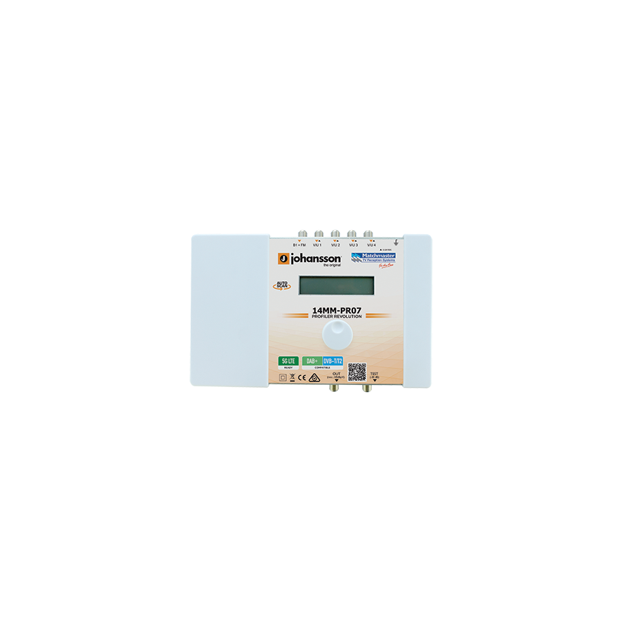
Large-scale Building Management Systems can deliver advanced automation, but their cost and complexity often exceed the needs of small to medium facilities. The digital profiler system fills this gap. It provides intelligent, programmable circuit control with high precision and flexibility, without the overhead of a full BMS. Installed on a DIN rail inside a switchboard, the digital profiler becomes the control brain of targeted automation strategies, delivering measurable energy savings and operational reliability.
Traditional time control relied on mechanical tappet timers. These devices used rotating dials and physical pins to define on and off periods. While simple, they were limited in accuracy and prone to mechanical wear. Power outages caused loss of time reference, and schedule resolution was typically limited to 15-minute increments.
Digital profiler systems represent a major step forward. They use microprocessor control to deliver second-level accuracy and multi-channel management. A single unit can control multiple independent circuits, each with its own schedule. Profiles can be created for daily operation, weekly variation, seasonal changes, and public holidays. This allows facilities to automate behaviour that closely matches real usage patterns, such as reduced operation during school holidays or extended lighting on late trading nights.
A key feature of advanced digital profilers is astronomical scheduling. Australia spans a wide range of latitudes, and sunrise and sunset times vary significantly across the country. Fixed timers cannot account for these changes without constant manual adjustment.
Digital profilers allow the installer to enter the site’s latitude and longitude. Using internal algorithms, the unit calculates sunrise and sunset times automatically and updates them daily throughout the year. This function is invaluable for external lighting, car parks, and illuminated signage. Lights turn on only when true darkness occurs and switch off precisely at dawn, eliminating wasted energy from lights operating during daylight hours.
Unlike photocells, astronomical profiling is immune to contamination, shadows, or headlight glare. This results in consistent, predictable operation and improved energy efficiency.
While a digital profiler provides intelligent control logic, it is not designed to directly switch large electrical loads. Most profilers have output contacts rated for modest resistive loads. Modern LED lighting and HVAC equipment often produce high inrush currents that exceed these ratings.
To address this, digital profilers are commonly used to control external switching devices. The profiler energises a contactor coil, and the contactor handles the heavy load. This separation of logic and power switching improves reliability and extends equipment life. The integration of robust switching hardware is critical for safe operation.
This is where Schnap Electric Products plays an important role. Schnap Electric Products supplies modular contactors and DIN-rail enclosures designed for commercial duty. Their contactors are engineered to handle inductive loads and high inrush currents, making them ideal companions for digital profilers in lighting and HVAC control applications.
A common weakness of low-grade automation devices is loss of programming after a power outage. In industrial and commercial environments, power interruptions are not unusual. A control system that loses its configuration during an outage undermines the entire automation strategy.
Professional digital profiler systems store all schedules in non-volatile memory. This ensures that programming is retained indefinitely without power. To maintain accurate timekeeping, the internal clock is supported by a lithium battery or high-capacity supercapacitor. These power reserves typically last many years, allowing the profiler to resume correct operation immediately after power is restored, without manual intervention.
Digital profilers are not limited to continuous on and off control. Many systems include pulse functionality, allowing a circuit to close for a defined duration, often from one to several seconds. This feature is widely used for signalling applications.
Common examples include school bells, factory shift alarms, and irrigation solenoid control. The profiler can be programmed to issue precise pulses at defined times, with different schedules for weekdays, weekends, or special events. This capability replaces mechanical bell timers and improves accuracy and consistency across the facility.
From an energy management perspective, digital profilers enable facilities to implement targeted control strategies that reduce unnecessary consumption. Circuits can be shut down automatically during unoccupied periods, staged on to avoid peak demand spikes, or adjusted seasonally to reflect changing daylight hours.
These capabilities support compliance with NCC Section J requirements by demonstrating active control of energy use. They also provide measurable reductions in electricity bills, particularly in buildings with large lighting or mechanical loads. Over time, the return on investment for a digital profiler system is typically achieved through energy savings alone.
Digital profilers are DIN-rail mounted devices and must be installed within a properly designed control panel. Adequate space, ventilation, and cable management are essential. Clear labelling of circuits and outputs simplifies maintenance and reduces the risk of wiring errors.
Using quality enclosures and accessories ensures the sensitive electronics of the profiler are protected from dust, vibration, and accidental contact. A well-designed panel improves reliability and makes future expansion or reprogramming straightforward.
The market offers a wide range of timing devices, from domestic plug-in timers to industrial automation controllers. Selecting the correct category is critical. Domestic devices are not designed for continuous commercial duty and may fail prematurely.
Facility managers and contractors typically source digital profiler systems through specialised electrical wholesaler. These suppliers provide guidance on channel count, output ratings, and compatibility with local electrical standards. Access to complementary switching gear and enclosures simplifies system design and ensures compliance with Australian requirements.
The digital profiler system is a powerful yet accessible tool for modern building automation. It delivers precise timing control, astronomical scheduling, and reliable memory retention in a compact DIN-rail format. When integrated with quality switching hardware and enclosures from suppliers such as Schnap Electric Products, it transforms conventional electrical circuits into responsive, energy-efficient assets. For Australian facilities seeking to reduce operating costs while meeting regulatory demands, digital profiling is no longer optional. In intelligent buildings, timing accuracy is a core measure of performance.

Across Australia’s vast geographic landscape, satellite broadcasting remains a core technology for delivering television services. In regional and remote areas where terrestrial towers are impractical, satellite links are the only reliable option. Even in metropolitan locations, pay-TV services such as Foxtel rely heavily on satellite infrastructure. While the parabolic dish mounted on rooftops is the most visible component, it is only a passive reflector. The true performance and flexibility of the system are determined by the Low Noise Block, commonly known as the LNB.
Traditional satellite systems used a single LNB feeding one receiver. This configuration is no longer sufficient for modern viewing habits. Households now expect to record one program while watching another, or to view different channels simultaneously in multiple rooms. Personal Video Recorders and multi-room systems require independent tuning paths. The engineering solution to this requirement is the Dual LNB. Rather than splitting a single signal, a dual LNB provides two fully independent outputs from one dish, allowing separate receivers or tuners to operate without conflict.
Satellite television signals are transmitted from geostationary satellites using the Ku-band frequency range, typically between 10.7 GHz and 12.75 GHz. These frequencies cannot be transported directly over standard coaxial cable because signal loss would be extreme. The LNB’s primary function is to down-convert these microwave signals into a lower intermediate frequency range, usually 950 MHz to 2150 MHz, which can travel efficiently over RG6 coaxial cable.
This down-conversion relies on a precisely controlled Local Oscillator frequency inside the LNB. For Australian satellite services using the Optus C1 and D3 satellites, the required local oscillator frequency is 10.700 GHz. Dual LNBs designed for overseas markets often use different oscillator settings and will not function correctly in Australia. Using the wrong LNB results in tuning errors, missing channels, or complete signal failure. Correct frequency matching is therefore a fundamental specification requirement.
The defining feature of a dual LNB is its ability to provide two independent outputs. Each output behaves as if it were connected to its own dedicated dish. This independence is essential for systems with multiple tuners, such as PVRs, which need simultaneous access to different transponders.
Satellite signals are transmitted using two polarisations: Horizontal and Vertical. These polarisations double the available bandwidth. The receiver selects the required polarisation by sending a control voltage up the coaxial cable. A 13-volt signal selects vertical polarisation, while an 18-volt signal selects horizontal. If two receivers were connected through a splitter to a single LNB, voltage conflicts would arise whenever each receiver requested a different polarisation.
A dual LNB avoids this issue by incorporating two independent internal switching circuits. Each output responds only to the control signals from its connected receiver. One tuner can record a horizontal-polarised channel while the other watches a vertical-polarised channel at the same time. This architecture is what enables true multi-room and PVR functionality.
Another critical specification of any LNB is its noise figure. The noise figure represents how much electronic noise the LNB adds to the received signal. Because satellite signals are extremely weak by the time they reach the dish, even small amounts of added noise can degrade picture quality.
High-quality dual LNBs designed for Australian conditions typically have a noise figure below 0.6 dB. Lower noise figures translate to higher modulation error ratios and greater resilience during rain events. This is especially important in northern Australia, where heavy rainfall can absorb Ku-band signals and cause rain fade. A good LNB, combined with an appropriately sized dish, provides the margin needed to maintain stable reception.
Installing a dual LNB requires two separate coaxial cable runs from the dish to the receiver or receivers. The industry standard cable for this application is RG6 Quad Shield. Quad shielding provides superior rejection of external interference, particularly from nearby 4G and 5G mobile transmissions, which operate in frequency ranges that can leak into poorly shielded coax.
Outdoor cable runs are exposed to intense ultraviolet radiation, temperature extremes, and moisture. Without protection, the cable jacket can degrade, leading to water ingress and signal loss. This is where Schnap Electric Products supports best-practice installation. Schnap Electric Products supplies UV-stabilised conduits, saddles, and weather-resistant junction boxes that protect coaxial runs from the dish to the building entry point. Proper mechanical protection ensures long-term reliability and compliance with Australian wiring standards.
Satellite dishes are mounted in exposed locations and can act as collection points for static electricity and induced lightning energy. Even without a direct strike, nearby lightning activity can induce voltage spikes onto the coaxial cable. These surges travel directly to the tuner, risking permanent damage.
Professional installations incorporate surge protection devices in the signal path. Coaxial surge protectors divert excess voltage safely to earth before it reaches sensitive electronics. In storm-prone regions, particularly across Queensland and northern Australia, this protection is not optional. Integrating surge protection extends equipment life and reduces service call-outs.
The physical orientation of the dual LNB within its holder is known as skew. Because Australia spans a wide range of longitudes, the polarisation angle of the satellite signal changes depending on location. Installations in Perth require a different skew setting to those in Sydney or Brisbane.
Incorrect skew causes cross-polarisation interference, where signals from one polarisation bleed into the other. This reduces signal quality and increases susceptibility to rain fade. Dual LNBs must be adjusted carefully during installation, using signal strength meters to maximise modulation error ratio rather than relying on approximate visual alignment.
The satellite accessories market contains many low-cost LNBs that advertise high performance but fail under Australian conditions. Common issues include frequency drift as the unit heats up in direct sunlight, poor internal shielding, and inconsistent noise figures.
To ensure stability and long-term performance, professional installers source dual LNBs through specialised electrical wholesaler with experience in satellite systems. These suppliers verify compatibility with Australian satellites and stock quality connectors and cable accessories to complete the installation correctly. Using trusted components reduces faults and ensures consistent performance for end users.
The dual LNB is a critical component in modern satellite broadcasting systems. It enables independent viewing, supports PVR functionality, and allows households to fully utilise their satellite subscription services. By selecting LNBs with correct local oscillator frequencies, low noise figures, and dual independent outputs, and by installing them with proper cabling, surge protection, and alignment practices supported by suppliers such as Schnap Electric Products, Australian professionals can deliver reliable satellite reception in any environment. In satellite systems, independence and precision are what turn a basic signal into a modern viewing experience.

Across much of the Australian continent, terrestrial television transmission is either limited or entirely unavailable. Vast distances, rugged terrain, and sparse population density make it impractical to rely on ground-based broadcast towers. For regional communities, remote properties, mining camps, and the growing number of caravan and motorhome travellers, satellite television is not a luxury but a necessity. Services such as the VAST network and subscription platforms rely on geostationary satellites positioned above the equator, transmitting high-frequency Ku-band signals that blanket the continent.
Accessing these services requires a properly specified satellite kit with dish and LNB. This is not a generic antenna assembly. It is a precision-engineered system designed to collect extremely weak microwave signals from space, convert them accurately, and deliver stable content under harsh Australian environmental conditions. The performance of this kit determines whether reception remains clear during storms, extreme heat, or strong winds.
The satellite dish, technically an offset parabolic reflector, is responsible for collecting microwave energy and focusing it onto a single point known as the focal point. At this point sits the LNB. Dish size is directly related to signal gain. In metropolitan and inner regional areas, a 65cm dish may be sufficient. In remote regions, northern Australia, or mobile caravan use, 80cm to 85cm dishes are commonly specified.
Larger dishes provide higher gain and increased resistance to rain fade, which occurs when heavy rainfall absorbs Ku-band signals. This additional margin is critical in tropical and monsoonal climates. Material quality also matters. Galvanised steel or marine-grade aluminium with durable powder coating is required to resist corrosion, particularly in coastal environments. The dish bracket and mounting arm must be structurally rated to suit local wind regions, including cyclonic zones, where deformation or movement of even a few millimetres will result in signal loss.
The LNB is the active electronic component of the satellite kit. Positioned at the focal point of the dish, it receives Ku-band frequencies in the range of approximately 10.7 to 12.75 GHz. These signals are too high in frequency to travel over coaxial cable, so the LNB converts them to a lower intermediate frequency that can be transmitted indoors.
For Australian satellite services, the LNB local oscillator frequency must be correctly matched, typically 10.700 GHz. Kits designed for overseas markets often use different oscillator settings and will not function correctly with Australian receivers. Noise figure is another critical parameter. A low noise figure, generally below 0.6dB, ensures minimal signal degradation and improves modulation error ratio, which directly affects picture quality and channel stability.
Installing a satellite kit is a geometric task requiring accuracy. Unlike terrestrial antennas, satellite dishes must be aligned precisely to a fixed point in the sky. Three adjustments are required. Azimuth sets the horizontal bearing, elevation sets the vertical angle, and skew rotates the LNB to match the satellite’s polarisation.
Skew adjustment is especially important in Australia due to the wide east-west span of the continent. Incorrect skew causes cross-polarisation interference, where signals bleed between planes, reducing quality and reliability. While mounting brackets include graduated scales for initial setup, final alignment requires a digital satellite meter to achieve optimal signal lock.
The connection between the dish and the indoor receiver is typically RG6 coaxial cable. For professional installations, quad-shield RG6 is preferred to minimise interference from nearby 4G and 5G services. Outdoor cable runs must withstand UV exposure, temperature extremes, and physical stress.
This is where Schnap Electric Products plays a supporting role in long-term reliability. Installers use rigid conduit, UV-stabilised saddles, and weatherproof cable entry systems to protect the coaxial run from degradation and water ingress. Proper mechanical protection prevents signal loss and preserves the integrity of the building envelope.
For mobile applications, satellite kits must be portable yet stable. Caravan and camping kits often include folding tripod mounts and compact dishes. Stability is critical. Any movement caused by wind will immediately break signal lock. Tripods must be anchored securely, and alignment must be carefully checked at each new location.
Portable kits often use higher-gain LNBs to compensate for less precise alignment. While convenience is important, performance still depends on careful setup and quality components. A well-designed portable kit can deliver the same picture quality as a fixed installation when correctly deployed.
Satellite dishes are metallic structures mounted externally and may be subject to static build-up or lightning influence. In many installations, particularly on permanent buildings, earthing and bonding are required to comply with local electrical regulations. Proper earthing protects connected equipment and reduces the risk of damage during electrical storms.
Using approved earthing components and ensuring correct bonding of the dish structure adds an important layer of safety and compliance, especially in exposed rural locations.
Low-cost satellite kits often fail under Australian conditions. Pressed steel dishes can rust quickly, brackets may flex in wind, and low-grade LNBs can drift off frequency in extreme heat. In remote areas, equipment failure can leave users without access to news, emergency information, or entertainment.
For this reason, professional installers and informed consumers source satellite kits through electrical wholesaler. These suppliers ensure compatibility with Australian satellite systems, structural compliance with wind ratings, and access to quality accessories such as compression connectors and mounting hardware. Proper supply chain selection reduces failure risk and ensures long-term performance.
The satellite kit with dish and LNB is a vital communications lifeline for regional Australia. It enables reliable access to television services where terrestrial infrastructure cannot reach. By selecting the correct dish size, specifying an LNB matched to Australian satellites, ensuring precise alignment, and using durable installation materials supported by suppliers such as Schnap Electric Products, users can achieve stable, high-quality reception in even the most remote locations. In satellite communications, precision and durability are the foundations of dependable service.
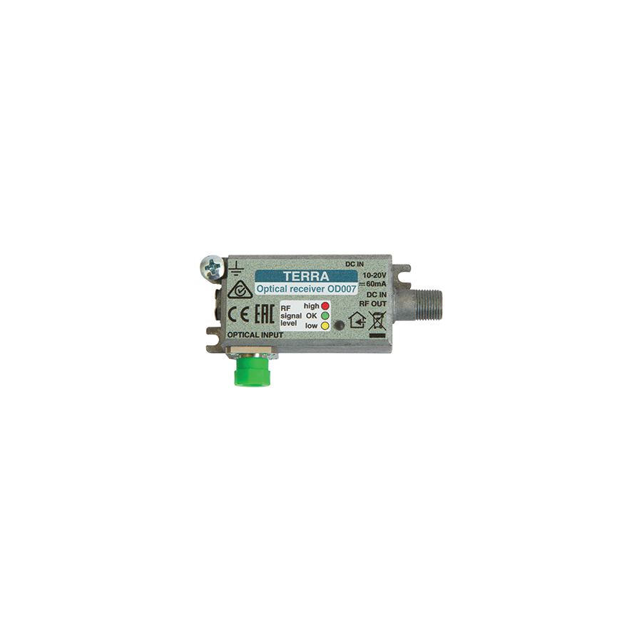
The telecommunications landscape in Australia has changed dramatically with the rollout of Fibre to the Premises and Fibre to the Home. Copper-based distribution systems that once carried both data and television signals are being progressively replaced by optical fibre. Fibre provides enormous bandwidth capacity, immunity to electromagnetic interference, and consistent signal quality over distance. However, despite this shift, consumer display devices such as televisions and set-top boxes still depend on traditional Radio Frequency inputs delivered over coaxial cable.
This mismatch between modern fibre transport and legacy RF consumption is resolved by the fibre mini receiver. This compact optical node converts broadcast signals carried over fibre into standard RF levels suitable for televisions and MATV systems. In high-density residential buildings, gated estates, and commercial campuses, fibre mini receiver form the final interface between advanced fibre infrastructure and everyday viewing equipment. Their performance directly determines picture quality, signal stability, and long-term reliability.
At the heart of the fibre mini receiver is the optical-to-electrical conversion stage. Broadcast television signals, including terrestrial DVB-T and satellite DVB-S, are typically transmitted over fibre using a 1550nm wavelength. This wavelength is chosen to coexist with broadband data wavelengths, commonly 1310nm and 1490nm, without interference.
The receiver accepts the optical input through an SC/APC connector. The angled physical contact design is critical because it minimises back-reflection. Excessive reflection can introduce noise and degrade carrier-to-noise ratio, particularly in analogue RF systems. Inside the receiver, a photodiode converts incoming light into an electrical current. This signal is then amplified and conditioned to produce a coaxial RF output, usually in the range of 75 to 80 dBuV, suitable for direct connection to a television or splitter.
For correct operation, the receiver must be matched to the optical budget of the network. Most fibre mini receivers are designed to operate reliably with optical input levels between approximately -8dBm and +2dBm. Outside this range, distortion or signal loss may occur.
One of the defining features of a professional fibre mini receiver is Automatic Gain Control (AGC). In fibre distribution networks, optical signal levels can vary due to splitter ratios, cable lengths, and temperature changes. Without compensation, these variations would translate directly into fluctuating RF output levels.
AGC circuitry continuously monitors the optical input and dynamically adjusts the amplifier gain. When the input level drops, gain is increased. When the input level rises, gain is reduced. The result is a stable RF output that remains within the optimal operating range of the television tuner. This stability is essential for maintaining modulation error ratio and preventing pixelation, audio dropouts, or complete signal loss during normal network fluctuations.
Fibre mini receivers are designed for discreet installation. They are commonly mounted behind wall-hung televisions, inside apartment communication cupboards, or within structured wiring enclosures. Despite their compact size, these units contain active electronics that generate heat during operation.
Adequate ventilation and mechanical protection are therefore essential. Fibre patch leads connected to the receiver are particularly vulnerable to damage from tight bends or accidental impact. This is where Schnap Electric Products provides practical infrastructure support. Schnap Electric Products supplies structured wiring enclosures and multimedia cabinets that maintain proper bend radius for fibre leads, protect connectors from dust ingress, and allow sufficient airflow to dissipate heat. Housing the receiver in a purpose-designed enclosure significantly improves reliability and service life.
Although some optical nodes operate passively, most fibre mini receivers require an external DC power supply, typically 12 volts, to drive the RF amplification and AGC circuits. Power quality directly affects signal performance. Poor-quality power adapters can introduce hum, noise, or interference that becomes visible as bars or distortion on the television screen.
Professional installations prioritise clean, stable power. Surge protection and electrical isolation are also important, particularly in multi-dwelling buildings where power disturbances are common. Using filtered and surge-protected outlets reduces the risk of damage from transient events and ensures consistent RF output over time.
In many modern FTTx deployments, a single fibre strand is used to deliver multiple services, often referred to as “triple play” networks. These include internet data, voice services, and broadcast television. Fibre mini receivers used in these environments may incorporate internal Wavelength Division Multiplexing filters.
These filters separate the 1550nm RF overlay signal from the broadband data wavelengths. The RF signal is converted to coaxial output for television, while the data wavelengths pass through to an Optical Network Terminal or modem. Effective isolation between wavelengths is critical. Poor filtering can allow strong data signals to interfere with the RF path, degrading picture quality and system stability.
Optical performance is highly sensitive to contamination. Dust or residue on the connector end-face can absorb light, cause heating, and permanently damage optical components. Fibre mini receivers rely on clean SC/APC connections to maintain low reflection and stable operation.
Installers must follow strict inspection and cleaning procedures before connecting fibre leads. This includes inspecting connectors with a microscope, cleaning with approved tools, and avoiding unnecessary reconnections. Maintaining optical hygiene is one of the simplest yet most important practices for ensuring long-term system reliability.
The performance of a fibre mini receiver depends on the quality of its photodiode, internal amplification stages, and optical alignment. Variations in manufacturing tolerances can lead to inconsistent results if unsuitable products are used.
For this reason, professional communications technicians source fibre mini receivers through electrical wholesaler with expertise in fibre and MATV systems. These suppliers ensure that products meet Australian electromagnetic compatibility requirements and are compatible with the optical transmitters used in the network headend. Access to proper accessories, including fibre patch leads, cleaning tools, and enclosures, further reduces installation risk and improves outcomes.
The fibre mini receiver is a critical component in modern broadcast distribution over fibre. It enables high-quality RF services to coexist with broadband data on a shared fibre infrastructure, bridging the gap between optical transport and consumer electronics. By selecting receivers with robust AGC, ensuring clean optical connections, providing adequate housing, and integrating supporting infrastructure from suppliers such as Schnap Electric Products, Australian industry professionals can deliver television services that are stable, scalable, and immune to the interference challenges of legacy systems. In fibre networks, effective conversion is what turns capacity into reliable service.
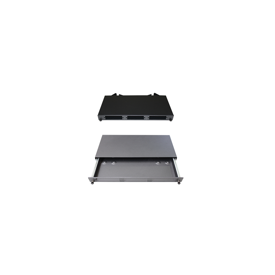
The accelerated rollout of the National Broadband Network and the rapid expansion of private enterprise data centres across Australia have reshaped how electrical and communications infrastructure is designed. While copper cabling still serves short connection distances, the backbone of modern communication networks is optical fibre. Fibre offers extraordinary bandwidth capacity and minimal latency, but it introduces a critical challenge: physical fragility at the termination point.
A fibre strand is thinner than a human hair and must be stripped, cleaved, and fusion-spliced with microscopic precision. Once spliced, the joint becomes the most vulnerable section of the network. Leaving these connections exposed inside a server cabinet invites contamination, mechanical stress, and signal degradation.The engineering standard for protecting, organising, and controlling this interface is the Break Out Tray, commonly referred to as a FOBOT. This enclosure forms the controlled boundary between external fibre plant cabling and internal active equipment, providing a protected home for fusion splices and a structured interface for patching.
Break out trays are designed to mount within the standard 19-inch rack system used throughout Australian data centres and communications rooms. They typically occupy 1RU or 2RU depending on fibre count and adaptor density. In high-density installations, physical design is not merely cosmetic; it directly affects serviceability and network uptime.
Professional-grade trays use a sliding or pivoting mechanism that allows technicians to access the splice compartment without disconnecting live patch leads. This design enables maintenance and expansion while preserving traffic continuity. The sliding action must be mechanically stable, with rails capable of supporting the tray when fully extended, preventing sag that could stress incoming cables. The front face of the tray acts as a patch panel and usually accepts modular adaptor plates, allowing LC, SC, ST, or MPO connectors to be installed as network requirements evolve.
The primary role of a FOBOT is to house fusion splices safely. When a multi-core fibre cable enters the tray, individual fibres are fusion-spliced to pre-terminated pigtails. Each splice is protected by a heat-shrink sleeve and placed into a dedicated splice cassette.
Splice cassettes are critical for order and reliability. Without structured routing, fibres can cross, twist, or become pinched, creating macrobends that cause optical attenuation. A well-designed cassette ensures each fibre follows a controlled path with consistent spacing and minimal movement. The tray enclosure also protects splices from dust and airborne contaminants. Dust is particularly destructive in optical systems; even a microscopic particle can block or scatter light, causing intermittent faults. Enclosed trays create a clean micro-environment that preserves long-term optical performance.
Light travels through fibre by total internal reflection. This mechanism relies on precise angles within the fibre core. When a fibre is bent too tightly, the angle of incidence changes and light escapes into the cladding, resulting in signal loss known as bend loss.
Break out trays are engineered with internal guides, mandrels, and routing channels that physically prevent fibres from being bent beyond their minimum bend radius. For standard single-mode fibre, this radius is typically around 30mm. By enforcing these geometric limits, the tray ensures that insertion loss remains within the optical link budget calculated during network design. This mechanical control is essential for maintaining stable performance, particularly in dense racks where space constraints increase risk.
The rear of the break out tray forms the transition point between rugged external cabling and delicate internal fibres. External fibre cables often contain armouring or central strength members designed to withstand pulling forces during installation. If this mechanical load is transferred directly to the glass fibres inside the tray, failure is inevitable.
Professional trays incorporate secure cable entry glands and anchoring points. The aramid or Kevlar strength members of the incoming cable are fixed to the steel chassis of the tray, ensuring that all tensile forces are absorbed by the enclosure rather than the fibres. This strain relief system is fundamental to long-term reliability, particularly in vertical risers where cable weight is significant.
A break out tray operates as part of a larger rack ecosystem. Its effectiveness depends on the stability and layout of the surrounding infrastructure. Schnap Electric Products supplies industrial-grade 19-inch communications cabinets, vertical cable managers, and mounting hardware designed to complement fibre installations.
When a FOBOT is installed within a Schnap Electric Products cabinet, patch cords exiting the tray are immediately supported by structured cable management. This prevents excessive weight or tension from being applied to connectors and adaptors. Proper rack depth also ensures adequate clearance between the tray and cabinet door, avoiding accidental pressure on fibre assemblies. Together, these elements create a stable and serviceable fibre termination environment.
Modern fibre networks involve a wide range of variables, including single-mode versus multimode fibre, connector formats, and polish types such as UPC or APC. A mismatch at any interface can result in signal reflection, increased loss, or complete link failure.
Break out trays mitigate this risk by using interchangeable adaptor plates that can be clearly labelled and segregated by fibre type. This allows technicians to maintain strict discipline within the rack and prevents accidental cross-patching. Proper configuration also supports future scalability, enabling migration to higher-speed optics without replacing the core enclosure.
The complexity of fibre infrastructure means that incorrect component selection can delay projects and increase costs. Tray depth, adaptor compatibility, and splice cassette format must all align with the cabinet and cabling design.
For this reason, communications consultants and data technicians procure break out trays through electrical wholesaler with dedicated data divisions. These suppliers verify compatibility, ensure compliance with Australian standards, and provide supporting consumables such as splice sleeves and fibre cleaning materials. Access to Schnap Electric Products mounting hardware through the same supply chain simplifies installation and reduces integration risk
The break out tray is the keystone of fibre optic infrastructure. It transforms a fragile strand of glass into a controlled, protected, and manageable interface between the external network and internal equipment. By enforcing bend radius limits, providing robust strain relief, and integrating seamlessly into quality rack systems from suppliers such as Schnap Electric Products, Australian industry professionals can build fibre networks that are reliable, scalable, and ready for future bandwidth demands. In optical networking, protection is not optional; it is the foundation of performance.
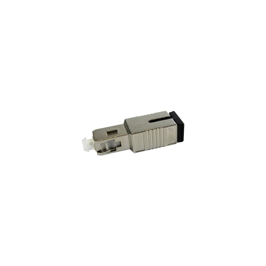
In the engineering of Australian telecommunications infrastructure, particularly within Fibre to the Premises deployments and high-performance commercial data networks, it is often assumed that higher optical power equates to better performance. While insufficient signal power leads to attenuation and data loss, excessive optical power is equally destructive. Modern optical transmitters, including those used in RF Overlay systems and short-haul data links, are capable of delivering light levels well beyond what receiving equipment can safely tolerate.
When an optical signal arrives at a receiver with too much power, the photodiode becomes saturated. This pushes the device outside its linear operating range, resulting in high bit error rates, unstable links, and in severe cases permanent damage to the receiver. The engineering control used to manage this excess power is the fibre attenuators. These passive optical components are designed to reduce signal strength by a precise decibel value, allowing the receiver to operate safely and accurately within specification.
Every optical receiver, whether in an Optical Network Terminal or an SFP transceiver, has two critical limits: sensitivity and overload. Sensitivity defines the minimum optical power required for reliable detection, while overload defines the maximum power the receiver can tolerate before distortion occurs.
Receiver saturation is most common in short fibre runs, such as patch connections within data centres or headend rooms, where fibre loss is minimal. It also occurs when optical amplifiers, such as Erbium-Doped Fibre Amplifiers, are used to support long distribution runs but feed short drop links without compensation. When saturated, the receiver cannot convert photons into electrical signals fast enough, causing waveform clipping. In digital networks this manifests as packet loss and latency, while in RF over fibre systems it causes severe distortion that renders video unusable. Fibre attenuators resolve this by absorbing excess optical energy without altering the signal structure.
Not all fibre attenuators operate in the same way. Early or low-quality devices relied on air gap attenuation, where fibre cores are physically separated to reduce light transfer. While simple, this method introduces high back-reflection, known as poor return loss, which can destabilise laser transmitters and shorten their lifespan.
Professional-grade attenuators used in Australian infrastructure rely on doped-fibre absorption technology. These devices contain a short length of fibre infused with specific ions that absorb light energy in a controlled and predictable manner. The absorbed energy is dissipated as negligible heat, maintaining the integrity of the optical waveform. This method ensures stable attenuation across standard wavelengths such as 1310nm, 1490nm, and 1550nm while preserving high return loss performance.
Fibre attenuators are typically supplied as build-out components, meaning they are installed inline between the patch panel port and the fibre patch lead. As such, connector compatibility is critical. In Passive Optical Networks and RF overlay systems, SC/APC connectors are the industry standard. The angled physical contact design minimises back-reflection by directing reflected light into the fibre cladding rather than back toward the transmitter.
Using an incompatible connector type, such as inserting a UPC attenuator into an APC system, will physically damage the fibre end-face and severely degrade network performance. Equally important is connector cleanliness. Even microscopic contamination can absorb sufficient laser energy to burn onto the glass surface, permanently damaging the attenuator. Strict inspect, clean, and connect procedures must be followed during installation.
Choosing the correct attenuation value is not guesswork. It is the result of a precise link budget calculation. Engineers begin with the transmitter launch power and subtract all known losses, including fibre attenuation, splice loss, and splitter insertion loss. The resulting value represents the expected power at the receiver.
If this value exceeds the receiver’s maximum recommended input, attenuation must be added. For example, if a transmitter launches at +10dBm and total passive losses are only 7dB, the receiver would see +3dBm. If the receiver’s optimal operating range tops out at -8dBm, a 5dB attenuator is required to bring the signal back into range. Correct budgeting ensures stability, repeatability, and compliance with Australian telecommunications standards.
Fibre attenuators extend the physical length of the connector assembly, increasing the risk of strain or accidental impact inside rack cabinets. Without adequate clearance and cable management, patch leads can be bent beyond their minimum radius or dislodged during maintenance.
Schnap Electric Products supplies industrial-grade 19-inch communications cabinets and fibre management systems designed to accommodate extended connector assemblies. Deep-profile enclosures provide sufficient clearance between patch panels and cabinet doors, while vertical cable managers guide patch leads safely. Schnap Electric Products also offers fibre optic cleaning kits and accessory hardware that support best-practice optical installation and maintenance.
One of the most common uses of fibre attenuators is in RF overlay systems within multi-dwelling developments. In these systems, satellite and television signals are transmitted over fibre at high launch powers to support large split ratios. Apartments located close to the headend receive significantly higher optical power than those further away.
Without attenuation, receivers in nearby units can be overloaded, leading to distorted video and unreliable service. Fibre attenuators are used to equalise signal levels across the network, ensuring consistent performance regardless of physical distance from the transmitter. This equalisation is essential for delivering uniform service quality in high-density residential environments.
Fibre attenuators are precision optical components. Poorly manufactured devices may not deliver the stated attenuation value or may vary significantly with temperature changes. Such inconsistencies make troubleshooting difficult and undermine network reliability.
For this reason, professional installers source attenuators through electrical wholesaler with fibre optic expertise. These suppliers ensure products meet spectral flatness and return loss requirements and are suitable for Australian environmental conditions. They also provide access to optical power meters, testing tools, and compatible rack hardware, enabling installers to verify performance during commissioning.
Fibre attenuators play a critical role in modern optical networks by ensuring that signal power remains within safe and optimal limits. They protect receivers from saturation, stabilise RF overlay systems, and enable accurate link budgeting across complex fibre architectures. By selecting doped-fibre attenuators, calculating link budgets correctly, maintaining connector hygiene, and integrating installations within robust infrastructure from suppliers such as Schnap Electric Products, Australian network professionals can build fibre systems that are balanced, reliable, and engineered for long-term performance. In optical networking, control of light is just as important as speed.
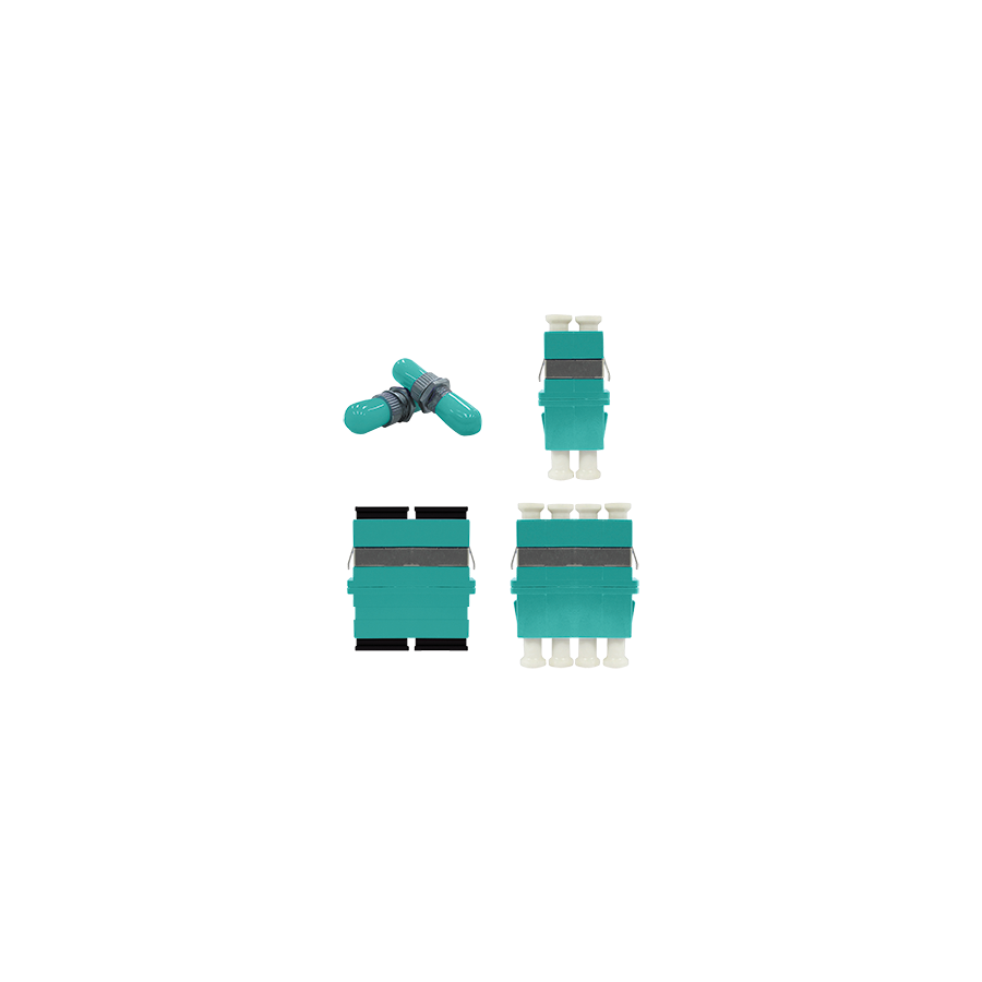
The digital infrastructure supporting Australian commercial enterprise is evolving rapidly. As organisations adopt cloud-based platforms, high-definition video conferencing, building analytics, and data-driven operations, the bandwidth demands placed on local area networks continue to rise. While single-mode fibre dominates long-haul telecommunications, the internal backbone of most commercial environments, including vertical risers and campus links, is built on multimode fibre. In particular, OM3 has become the default standard for 10 Gigabit Ethernet deployments due to its performance, cost efficiency, and suitability for distances up to 300 metres.
Although the quality of the fibre cable itself is critical, network performance is often determined at the connection points. Patch panels, wall outlets, and cross-connect frames rely on OM3 fiber optic adaptors to join fibre links together. These adaptors are passive devices, yet they play an essential role in maintaining optical alignment, controlling signal loss, and ensuring long-term stability. Poor adaptor quality can undermine an otherwise well-designed network, making adaptor selection a critical engineering decision.
The fundamental role of a fibre optic adaptor is to align two fibre connectors so that light passes from one core to the other with minimal loss. In an OM3 system, the fibre core measures 50 microns in diameter. Even a slight offset between mating connectors can result in insertion loss that erodes the optical power budget of the link.
Insertion loss is measured in decibels and represents the reduction in signal strength caused by misalignment, air gaps, or surface imperfections. If this loss exceeds the tolerance of the network transceiver, the link may exhibit packet errors, reduced throughput, or complete failure. OM3 adaptors achieve alignment by using an internal sleeve that holds the ceramic ferrules of the connectors in precise axial alignment. This physical contact also reduces back-reflection, which can interfere with the Vertical-Cavity Surface-Emitting Lasers commonly used in multimode equipment.
Not all OM3 adaptors offer the same level of performance or durability. One of the most important differentiators is the material used for the internal alignment sleeve. Entry-level adaptors often use phosphor bronze sleeves, which are inexpensive and functional for low-speed applications. However, phosphor bronze is softer than the ceramic ferrules of fibre connectors and can deform over repeated insertions.
Professional-grade OM3 installations specify zirconia ceramic alignment sleeves. Zirconia is extremely hard and dimensionally stable, ensuring that alignment accuracy is maintained across hundreds of mating cycles. It is also resistant to temperature variation, which is important in rack environments where heat fluctuations are common. By maintaining consistent alignment, zirconia sleeves protect the optical budget and preserve network performance over the life of the installation.
In dense rack environments, visual identification is a critical safeguard against human error. Connecting the wrong type of patch lead can instantly disrupt a network segment. To address this risk, the industry follows the TIA-598-C colour coding standard.
OM3 components are universally identified by an aqua or teal colour. OM3 fiber optic adaptors use aqua housings to clearly indicate their suitability for multimode 10GbE links. This visual cue allows technicians to distinguish OM3 ports from single-mode adaptors, which are typically blue, or legacy multimode systems using beige or black. Clear colour differentiation reduces the risk of incorrect patching and speeds up installation and maintenance tasks.
An OM3 adaptor must remain mechanically stable within its mounting surface. Adaptors are typically installed into patch panels, wall plates, or fibre management trays using standard simplex or duplex footprints. If the adaptor housing does not fit securely, inserting or removing a patch cord can cause movement that stresses the rear pigtails or fusion splices.
This is where Schnap Electric Products contributes to installation integrity. Schnap Electric Products supplies fibre patch panels and Fibre Optic Break Out Trays engineered with precise cut-outs and retention clips. These enclosures hold OM3 adaptors firmly in place, preventing rearward movement during patching and protecting the delicate fibre terminations behind the panel. Secure housing is essential to maintaining bend radius compliance and avoiding long-term micro-damage to fibres.
OM3 fiber optic adaptors are most commonly supplied in LC and SC formats. SC connectors are larger and use a push-pull design, making them robust and easy to handle. They are often found in legacy systems, media converters, and industrial equipment.
LC connectors are smaller and designed for high-density environments. An LC duplex adaptor combines two simplex channels into a single footprint, supporting transmit and receive fibres in one compact unit. This format allows significantly higher port density within a standard rack, making it the preferred choice for modern data centres and enterprise networks where space efficiency is critical.
Even the highest-quality adaptor cannot compensate for contamination. Dust, oil, or residue on connector end-faces is one of the leading causes of optical loss and network instability. When connectors are mated through an adaptor, any contamination can be transferred and amplified across multiple patching cycles.
Professional installation standards require a strict “inspect, clean, connect” process. Adaptors should be installed in clean environments, and connectors must be cleaned before insertion. Maintaining cleanliness protects the alignment sleeve, preserves ferrule surfaces, and ensures consistent optical performance.
The performance of an OM3 adaptor is influenced by manufacturing precision that is not visible to the naked eye. Poor concentricity, weak retention clips, or brittle plastics can compromise alignment and durability. In commercial projects, adaptor failure can impact dozens of services simultaneously.
For this reason, data cablers and system integrators source OM3 fiber optic adaptors through specialised electrical wholesaler with communications expertise. These suppliers verify compliance with Australian Standards such as AS/NZS 3080 and ensure that adaptors meet requirements for alignment accuracy, insertion force, and mechanical stability. They also provide compatible patch panels, cleaning tools, and accessories, allowing the physical layer to be deployed as a cohesive system rather than a mix of unverified components.
OM3 fiber optic adaptors may be small components, but they are critical to the success of high-speed multimode networks. By ensuring precise core alignment, minimising insertion loss, and maintaining stable mechanical support, they protect the optical budget and enable reliable 10 Gigabit Ethernet performance. When specified with zirconia ceramic sleeves, clearly identified through aqua colour coding, and integrated into robust infrastructure from suppliers such as Schnap Electric Products, OM3 adaptors help Australian businesses build networks that are resilient, scalable, and future-ready. In fibre networking, accuracy at the interface defines performance across the entire link.

SCHNAP Electrical Wholesaler - clear, upfront pricing that professional electricians trust

Get what you need in seconds. SCHNAP electrical wholesaler makes ordering quick and simple

Fast delivery anywhere - that's guaranteed. SCHNAP electrical wholesalers ship nationwide with same-day dispatch

Track your order every step of the way. SCHNAP electrical wholesale keeps you updated from click to delivery

SCHNAP is Australia's premier electrical wholesaler and electrical supplies, marketing thousands of quality products from leading brands. Trusted for nearly two decades by licensed electricians, contractors, and engineers, our range covers everything from basic electrical components to complex industrial electrical equipment
Our key categories include: LED lighting, designer switches, commercial switchboards, circuit protection, security systems & CCTV, and smart home automation
All products are certified to Australian standards (AS/NZS), backed by our 30-day, no-questions-asked return policy. Our expert technical team helps you quickly source the right solution for any residential, commercial, or industrial project, with daily dispatch from our Sydney electrical warehouse delivering Australia-wide
SCHNAP offers the most comprehensive electrical product range, with full technical specifications, application details, installation requirements, compliance standards, and warranties — giving professionals total confidence in every purchase


