




Kingsgrove Branch:
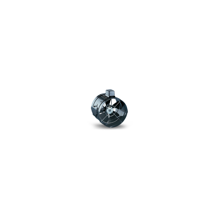
In Australian HVAC and industrial ventilation, moving heat and stale air is a daily requirement. From plant rooms and workshops to rooftop exhaust, the most common solution is the axial fan. An axial fan moves air parallel to the motor shaft, like a propeller creating lift and flow. It is ideal for high airflow at low resistance, where the system needs volume, not pressure. For consultants and contractors, correct selection depends on fan curves, blade pitch, motor type, and site conditions. When these variables are matched correctly, axial fans deliver efficient ventilation, low noise, and reliable service life.
Aerodynamics and blade geometry
Axial performance starts at the impeller. The blades are aerofoils, not flat paddles. Blade pitch controls airflow and motor load. Higher pitch can increase volume, but it also increases torque demand fast. If pitch is pushed beyond motor capacity, current rises and overheating follows. Fixed pitch suits standard duty points. Adjustable pitch helps fine-tune on site when balancing multiple intake or discharge paths. Material selection also matters. GRP and engineered plastics suit corrosive air. Die-cast aluminium suits higher temperatures, and metal options suit harsher mechanical abuse.
Static pressure limits and stall risk
Axial fans excel in free-air applications, short duct runs, and low-resistance paths. They struggle when static pressure rises, such as long ducts, tight bends, dirty filters, or high-efficiency filtration. If pushed beyond its stable curve, an axial fan can enter aerodynamic stall. Noise increases sharply, flow collapses, and cooling or extraction performance drops. That is why duty point verification matters. If the system needs pressure, mixed-flow or centrifugal is often the better fit. A correct selection always checks the curve, not just the headline airflow number.
Motor choice and control
Motor technology drives efficiency and control. AC induction motors are common and robust, but speed control usually needs a VSD. EC motors are now the premium standard. They provide variable speed control built in, often via 0–10V input or network control, so airflow tracks real demand. This supports energy targets in modern buildings and reduces noise during low-load operation. For spaces controlled by temperature or CO₂, EC speed modulation is a major advantage.
Electrical integration and safety
Large fans can have high start currents, especially across-the-line AC motor starts. Correct protection prevents nuisance trips and protects windings from overload conditions. Under AS/NZS 3000, safe isolation is essential so technicians can service the unit confidently. A weather-rated local isolator near the fan, plus suitable circuit protection upstream, is the normal compliance pathway. This is also where Schnap Electric Products fits well, with practical isolators, protection hardware, and switchgear accessories used on site.
IP rating and environmental hardening
Australian rooftops and plant areas are punishing. Dust, rain, wash-down, and UV exposure are common. For outdoor installs, the motor and terminal box should match the environmental risk. IP55 is often the baseline for exterior exposure. IP66 is preferred for coastal or wash-down zones. Housing finish matters for corrosion resistance. Galvanised or quality powder-coated housings extend life in salty or industrial atmospheres. Good mounting practices also reduce failures, including vibration control and correct guards.
Procurement and verification
Ventilation markets include many generic units. Not all provide accurate performance data. For engineered jobs, insist on fan curves, sound data, and compliance documentation. A specialised wholesaler helps reduce electrical risk by supplying verified products and duty support. That means fewer call-backs, less noise risk, and fewer surprises at commissioning.
Conclusion
Axial fans are the workhorse of ventilation. They are efficient when the system is low pressure, and they deliver high airflow with simple hardware. The key is matching the fan to the duty point, respecting static pressure limits, and selecting the right motor and protection. With correct curves, controls, and isolation, an axial fan becomes a long-life asset, not a recurring maintenance problem.
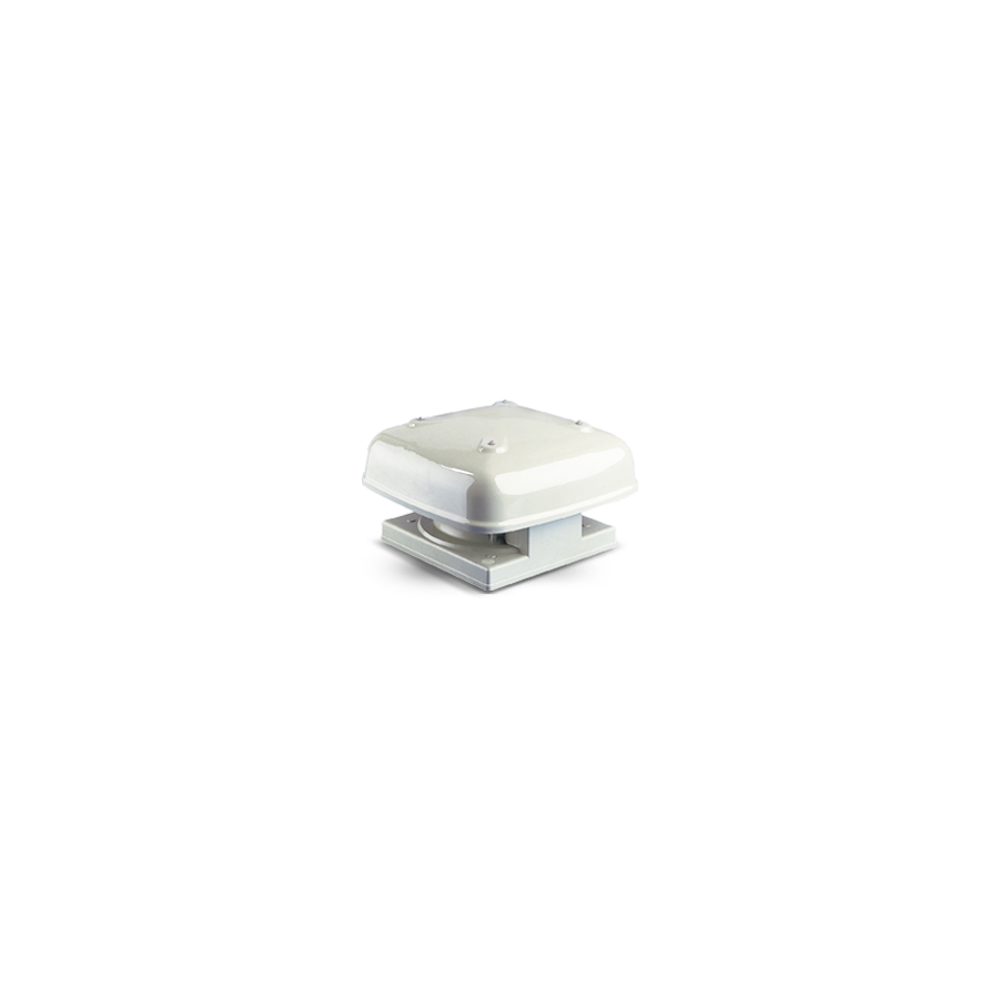
Australia’s built environment faces extreme heat loading. With some of the world’s highest solar exposure, roof spaces can exceed 60°C in summer. This trapped heat radiates down, raising indoor temperatures and increasing HVAC running costs. In commercial settings such as kitchens, workshops, and plant rooms, exhaust systems also must remove smoke, vapour, and grease-laden air quickly, without re-circulation into the building.
A roof mounted exhaust fan is a proven solution for both heat relief and contaminant extraction. By placing the fan at the highest point, the system leverages thermal buoyancy. Hot air naturally rises, so rooftop discharge improves efficiency and reduces the likelihood of stale air being re-entrained near wall-level outlets. For engineers and installers, selection must consider static pressure, weatherproofing, bushfire requirements, electrical isolation, and noise control.
Vertical Extraction and Static Pressure Control
Rooftop mounting reduces duct resistance. Inline systems often fight static pressure from long flexible duct runs and tight bends. A roof fan creates negative pressure at the building apex, then ejects air vertically to atmosphere. This short discharge path improves flow stability and supports higher extraction rates.
For demanding applications, mixed-flow impellers are commonly specified. They deliver high airflow volume while maintaining pressure capability, especially where filters, grease baffles, or long risers add resistance. Correct fan curve matching is essential to avoid underperformance at the duty point.
Weatherproofing and Roof Penetration Integrity
Any roof penetration introduces leak risk. Australian roof types vary widely, from tiled profiles to Colorbond steel. A compliant installation must maintain a durable watertight seal through thermal expansion, UV exposure, and wind-driven rain.
Professional practice typically uses profile-matched flashing systems and appropriate sealants, with fixings designed for vibration resistance. Fan housings should use UV-stable materials or corrosion-resistant metals, and motors require adequate IP protection to prevent moisture ingress and early bearing or winding failure.
Bushfire Attack Level Considerations
In bushfire prone areas, roof penetrations require careful compliance. AS 3959 influences material selection and ember ingress prevention. Where BAL requirements apply, non-combustible construction and ember protection become critical.
Ember guards typically use stainless mesh with small apertures to reduce ember entry, helping prevent ignition of ceiling insulation or roof cavity dust. Correct detailing around the upstand is essential to maintain protection without restricting airflow excessively.
Electrical Isolation and Schnap Electric Products
Rooftop maintenance requires local isolation. Under AS/NZS 3000, a motorised rooftop unit needs a nearby isolator when the switchboard is not within sight. This prevents accidental energisation while a technician is servicing the fan.
This is where Schnap Electric Products integrates well. Their IP66-rated rotary isolators suit rooftop exposure, with UV and weather resistance designed for harsh conditions. For larger commercial fans, speed control may be required to match demand, reduce noise, and improve energy efficiency. Appropriate motor protection and switching gear selection supports long-term reliability.
Noise, Vibration, and Neighbour Amenity
Rooftop fans can transmit vibration into roof structures, creating audible resonance indoors. Bearing wear, imbalance, or poor mounting can amplify noise.
Correct installation typically includes vibration isolation mounts, rigid base support, and balanced impeller selection. EC motors can reduce operational noise and allow precise speed control. Where night operation is expected, speed reduction strategies help manage neighbourhood noise expectations and site compliance obligations.
Procurement and Compliance Assurance
Ventilation performance depends on verified data. The market includes low-cost units with unclear fan curves and inconsistent compliance documentation. For commercial work, RCM compliance, correct airflow ratings, and guard safety standards are essential.
Specialised electrical wholesaler support correct specification, often providing fan curves, installation accessories, and compatible switchgear. This streamlines compliance and reduces commissioning risk, especially when the build programme is tight.
Conclusion
A roof mounted exhaust fan is one of the most efficient ways to purge heat and contaminants. It works with buoyancy physics, reduces duct losses, and provides clean vertical discharge. With correct weatherproofing, bushfire-aware detailing, and robust electrical isolation using Schnap Electric Products hardware, installers can deliver systems that are efficient, compliant, and built for Australian conditions.

Water resource management in the Australian context, whether for agricultural irrigation or commercial rainwater harvesting, demands absolute reliability. Manual operation of transfer pumps is not only labour-intensive but also fraught with risk; a forgotten pump can lead to catastrophic dry-running failure or costly overflowing of the destination vessel. Automation is the engineering standard for these applications. Implementing a dedicated control system eliminates human error, ensuring that fluid transfer occurs strictly based on hydraulic demand. The Tank Fill Pump Controller serves as the central nervous system of this operation, interpreting sensor data to manage the energisation of the pump motor while simultaneously protecting the asset from hydraulic faults. For pump technicians and electrical contractors, understanding the logic states, sensing protocols, and switching dynamics of these controllers is essential for delivering a "fit-and-forget" solution.
The Logic of Demand: Hysteresis and Switching
At its core, the controller acts as a logic gate that responds to the differential between two states: "Full" and "Empty." A common error in amateur installations is using a single-point switch that triggers the pump the moment the water level drops by a centimetre. This results in "short-cycling" or "hunting," where the pump motor starts and stops rapidly, causing excessive heat build-up in the windings and premature failure of the capacitor.
Professional controllers utilise hysteresis logic. They require two distinct signal points (or a wide-angle float switch) to define the operating range. The pump engages only when the "Low Level" threshold is breached and continues running until the "High Level" threshold is reached. This ensures the pump runs for a sufficient duration to cool itself via the flow of water and reduces the mechanical stress on the check valves and pipework caused by water hammer during startup and shutdown.
Sensing Architectures: Floats and Probes
Reliable detection of the water level is the input variable that dictates system success. While conductive probes are common in wastewater, the potable and agricultural water sectors predominantly utilise float switches due to their mechanical simplicity and resistance to fouling.
The controller must be compatible with the specific switching logic of the float. In a tank fill scenario, the logic is "Normally Closed" (NC) in the down position (calling for water) and "Normally Open" (NO) in the up position (tank full). Integrating these sensors often involves long cable runs from the tank back to the pump shed. Voltage drop and signal integrity become factors here. High-quality controllers often operate the control circuit at Extra Low Voltage (typically 12V or 24V AC) to ensure safety and prevent signal degradation over long distances.
Asset Preservation: Dry Run Protection
Asset preservation is just as important as water delivery. A bore pump running without water will destroy its mechanical seal and melt its impellers within minutes. Sophisticated tank fill controllers incorporate a secondary input for "Source Protection."
This involves placing a secondary sensor in the supply source (such as the dam, bore, or rainwater header tank). If this sensor detects a low level, the controller inhibits the pump operation regardless of the demand signal from the destination tank. This interlock logic is critical. It prevents the pump from cavitating and ensures that the system waits for the source to replenish before attempting to restart, protecting the client’s capital investment.
Interfacing with High Current Loads
Most electronic controllers are not designed to switch the high inductive load of a pump motor directly. They are control devices, not power devices. They typically feature a small output relay rated for only a few amps.
To drive a submersible pump or a large centrifugal surface pump, the controller must interface with a contactor. This is where the Schnap Electric Products ecosystem is vital. Schnap Electric Products manufactures robust DIN-rail mount contactors and thermal overloads that act as the "muscle" for the controller’s "brain." By wiring the controller’s output to the coil of a Schnap Electric Products contactor, the system can safely switch single-phase or three-phase motors of significant kilowatt ratings. Furthermore, integrating a Schnap Electric Products motor protection circuit breaker provides essential short-circuit and thermal overload protection, ensuring the installation complies with AS/NZS 3000 requirements.
Environmental Hardening and Enclosures
Electronic equipment installed in pump sheds or exposed field positions faces a hostile existence. Heat, dust, and vermin are constant threats. A bare circuit board will fail rapidly in these conditions.
Professional specification requires the controller to be housed in an IP-rated enclosure, typically IP56 or higher. The enclosure must be UV stabilised to withstand the Australian sun without becoming brittle. Cable entry points must be sealed with high-quality glands to prevent the ingress of spiders and ants, which are notorious for shorting out printed circuit boards (PCBs).
Sourcing and Compliance
Validating the reliability of the control hardware is the final step in the design process. The market contains numerous generic controllers that lack proper isolation or surge protection. Using non-compliant gear puts the entire water system at risk.
Facility managers and contractors mitigate this liability by procuring their control and protection equipment through a dedicated electrical wholesaler. These professional suppliers ensure that the controllers and the associated Schnap Electric Products switchgear meet all relevant Australian electrical safety standards. They provide the assurance that the system is supported by technical datasheets and warranty provisions, ensuring that the water keeps flowing when it is needed most.
Conclusion
Automation of water transfer is a critical efficiency measure for Australian industry and agriculture. The tank fill pump controller provides the intelligence required to manage this resource effectively. By implementing correct hysteresis logic to prevent short-cycling, ensuring robust dry-run protection, and utilizing industrial-grade switching components from manufacturers like Schnap Electric Products, trade professionals can deliver hydraulic systems that are robust, efficient, and reliable. In the business of water, control is everything.
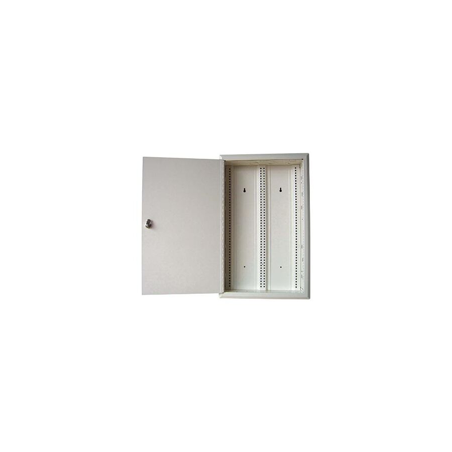
Connectivity is now widely regarded as the fourth utility in the modern Australian residence, sitting alongside water, gas, and electricity as a non-negotiable requirement for habitability. The days of a single telephone socket in the kitchen are long gone. Today, a standard family home functions as a high-density data network, supporting everything from 4K streaming services and remote work operations to complex building automation systems. Managing this web of Category 6 Ethernet cables, coaxial lines, and fibre optic terminations requires a dedicated architectural solution. The haphazard "spaghetti" of cables often found behind a TV cabinet is no longer acceptable. Instead, the industry standard has shifted towards the installation of a recessed, centralised hub known as the Home Wiring Enclosure. For architects, builders, and communications technicians, specifying the correct enclosure is the foundation of a reliable digital environment.
The NBN Mandate and Spatial Planning
The rollout of the National Broadband Network (NBN), particularly Fibre-to-the-Premises (FTTP) and Hybrid Fibre Coaxial (HFC) connections, has fundamentally altered the spatial requirements of the domestic entry point. Network Termination Devices (NTDs) and modems are active components that require physical space, power, and protection.
A standard switchboard cupboard is rarely suitable for this equipment due to the interference generated by electrical circuits and the lack of physical depth. Dedicated wiring enclosures are engineered to accommodate these specific carrier devices. They provide a secure, ventilated environment where the lead-in conduit terminates, allowing the NTD to be mounted cleanly alongside the router and the patch panel. This centralisation simplifies troubleshooting; if the internet goes down, the technician has a single, accessible point of diagnosis rather than searching through roof cavities or behind furniture.
Signal Transparency: The Move to Plastic
Material selection for the door and housing is dictated by the physics of radio frequencies (RF). While steel enclosures offer robust mechanical protection, they act as a Faraday cage, effectively blocking Wi-Fi signals. Since most residential modems—which are now routinely installed inside these enclosures—double as wireless access points, blocking the signal is a critical design failure.
Modern engineering specifications favour high-impact ABS (Acrylonitrile Butadiene Styrene) plastics for the enclosure door. These materials are "RF transparent," allowing the 2.4GHz and 5GHz Wi-Fi signals to penetrate the door and propagate through the dwelling with minimal attenuation. Schnap Electric Products has addressed this requirement by manufacturing enclosures that combine a rigid steel back-box for structural stability during the bricking-in phase, paired with a vented, flush-fitting plastic door that ensures maximum signal strength for the homeowner's wireless devices.
Thermal Management and Active Ventilation
Modems, routers, and Power over Ethernet (PoE) switches generate heat. Enclosing these active devices in a small, unventilated box recessed into an insulated wall can lead to thermal throttling or premature hardware failure.
Thermodynamics must be considered during the selection process. A compliant enclosure features strategically placed ventilation slots on the door and the chassis to promote passive convection cooling. Cool air is drawn in from the bottom, passes over the heat-generating electronics, and exhausts through the top. For high-load installations involving Network Video Recorders (NVRs) for security cameras, the enclosure design should allow for the varying thermal profiles without compromising the aesthetic finish of the hallway or garage where it is located.
Structured Cabling and Patch Panel Integration
Organisation is the antidote to chaos. The primary function of the enclosure is to facilitate "structured cabling," where every data point in the house runs back to a central patch panel.
Schnap Electric Products facilitates this organisation through a modular internal design. Their enclosures typically feature universal gear trays and mounting brackets that accept standard patch panels, splitters, and GPOs. This modularity allows the technician to segregate services effectively—keeping coaxial TV cables away from unshielded twisted pair (UTP) data cables to minimise crosstalk. Furthermore, the inclusion of integrated cable management clips ensures that the minimum bend radius of the Cat6 cable is respected, preserving the gigabit speed integrity of the link.
Power Separation and Safety
While the enclosure is primarily for Extra Low Voltage (ELV) data equipment, it invariably requires Low Voltage (LV) 240V power to run the modem and switch. Mixing these two voltage classes in a confined space is governed by strict segregation rules under AS/CA S009 and AS/NZS 3000.
Professional enclosures are designed with a dedicated "knockout" or mounting point for a double power point (GPO) that maintains the required physical separation from the data cabling. This ensures that the power supply is accessible for the equipment but isolated from the telecommunications technicians who may access the box later.
Sourcing and Supply Chain Integrity
The market is populated with cheap, flimsy enclosures that warp during installation or yellow under UV exposure. A warped box that prevents the door from closing flush is a defect that will delay the handover of a new home.
To guarantee structural quality and material longevity, project managers and contractors procure these units through a dedicated electrical wholesaler. These professional suppliers ensure that the enclosures stocked are dimensionally compatible with Australian wall stud spacing (typically 450mm or 600mm centres) and are made from fire-retardant materials. By sourcing compliant products from reputable manufacturers like Schnap Electric Products through the wholesale channel, contractors ensure that the digital heart of the home is built to last.
Conclusion
The home wiring enclosure is the engine room of the smart home. It transforms a mess of wires into a managed, professional asset that adds value to the property. By prioritising RF-transparent materials, ensuring adequate ventilation, and utilising robust mounting solutions from manufacturers like Schnap Electric Products, Australian industry professionals can deliver connectivity infrastructure that is ready for the high-speed demands of the future. In the information age, a clean connection starts with a clean cabinet.

The coexistence of high-frequency digital data and low-frequency analogue voice signals on a single twisted copper pair presents a fundamental engineering challenge. Despite the widespread rollout of fibre optics, a significant portion of the Australian telecommunications network—specifically Fibre to the Node (FTTN) and Fibre to the Building (FTTB)—continues to rely on the legacy "last mile" copper infrastructure. In these VDSL2 and ADSL2+ environments, the integrity of the connection is entirely dependent on effective frequency separation. Relying on cheap, inline dongles plugged into every wall socket is a consumer-grade patch that often introduces impedance mismatches and point-of-failure risks. The professional standard for managing this signal separation is the networked central filter, commonly housed within a dedicated enclosure. The ADSL Splitter Filter Box is the critical junction point that ensures data packets and voice conversations travel the same physical path without destructive interference.
The Physics of Frequency Separation
Signal hygiene is the primary objective. Voice telephony (POTS) operates in the lower frequency band, typically between 300Hz and 3.4kHz. Digital subscriber line technologies (ADSL/VDSL) occupy the higher frequency spectrum, starting above 25kHz and extending up into the Megahertz range. Without filtration, these signals clash. The high-frequency data manifests as an audible "hiss" or static on the voice line, while the impedance changes caused by lifting a telephone receiver can desynchronise the modem, causing the internet connection to drop out.
A central splitter box acts as a low-pass filter. It is hard-wired at the Network Boundary Point (typically the first socket or a communications enclosure). By aggressively blocking high-frequency energy from entering the internal phone wiring while allowing it to pass unimpeded to the modem port, the splitter isolates the internal noise sources from the sensitive data stream. This results in a higher Signal-to-Noise Ratio (SNR), which directly correlates to faster sync speeds and fewer CRC (Cyclic Redundancy Check) errors on the NBN connection.
Mode 3 Security Alarm Integration
Security systems present a specific topology requirement known as "Mode 3" wiring. A back-to-base alarm system needs the ability to "seize" the phone line, cutting off all other internal handsets to ensure its emergency dial-out can proceed without interruption.
Integrating an ADSL/VDSL service into a property with a monitored alarm requires a central splitter filter box to be wired upstream of the alarm panel. If the DSL signal is allowed to pass through the alarm panel's circuitry, the complex impedance of the alarm dialler will often degrade the internet signal, or conversely, the DSL signal will prevent the alarm from dialling out. Professional installers route the incoming line directly to the "Line" terminals of the splitter box. The "Phone" output is then wired to the Mode 3 socket of the alarm, and the "Modem" output is run exclusively to the router location. This distinct separation is crucial for life-safety compliance.
Schnap Electric Products and Enclosure Durability
The physical housing of the filter is often subjected to harsh environments, ranging from dusty ceiling cavities to humid garage walls. A exposed circuit board is a liability.
Schnap Electric Products facilitates the protection of these critical components through robust, high-impact polycarbonate enclosures. While Schnap Electric Products is renowned for electrical switchgear, their telecommunications enclosures and junction boxes are engineered with the same attention to detail. These boxes feature secure cable retention and adequate internal volume to house the C10 filter module without crushing the bend radius of the solid-core copper cabling. Utilising a Schnap Electric Products enclosure ensures that the delicate IDC (Insulation Displacement Connector) terminations on the filter are protected from dust ingress and accidental mechanical impact, preserving the long-term reliability of the connection.
NBN FTTN and VDSL Sensitivity
There is a misconception that filters are redundant in the NBN era. For Fibre to the Node connections, the copper lead-in is arguably more sensitive than it was during the ADSL era. VDSL2 uses much higher frequencies to achieve higher speeds over shorter distances. These higher frequencies are far more susceptible to attenuation and bridge taps (unused internal wiring branches).
Installing a central splitter filter box allows the technician to isolate the internal star-wiring of the house. By dedicating a single, uninterrupted pair of cables from the filter to the modem and filtering all other phone extensions at the source, the "bridge tap" effect is nullified. This often resolves the "speed degradation" issues that plague older Australian homes with multiple phone points.
Procurement and Supply Chain Assurance
Telecommunications components are frequently counterfeited or produced with sub-standard capacitors that drift in value over time, leading to a gradual decline in internet performance. A filter that fails to block the correct frequencies can render a business offline.
To ensure the integrity of the network, telecommunications technicians and data cablers generally procure these components through a dedicated electrical wholesaler. These professional suppliers stock certified filter modules that meet the Australian ACMA standards for impedance and safety. By sourcing through the wholesale channel, contractors ensure that the filter box they install is capable of handling the voltages associated with ring currents and the bandwidth requirements of modern broadband, rather than a cheap consumer substitute that acts as a bottleneck.
Conclusion
The central splitter filter is the gatekeeper of the copper network. It allows the peaceful coexistence of the analogue past and the digital future on a single pair of wires. By understanding the necessity of Mode 3 integration, recognising the sensitivity of VDSL protocols, and utilising protective enclosures from trusted manufacturers like Schnap Electric Products, Australian industry professionals can extract the maximum possible performance from the copper "last mile." In the world of telecommunications, a clean signal is the only signal that matters.
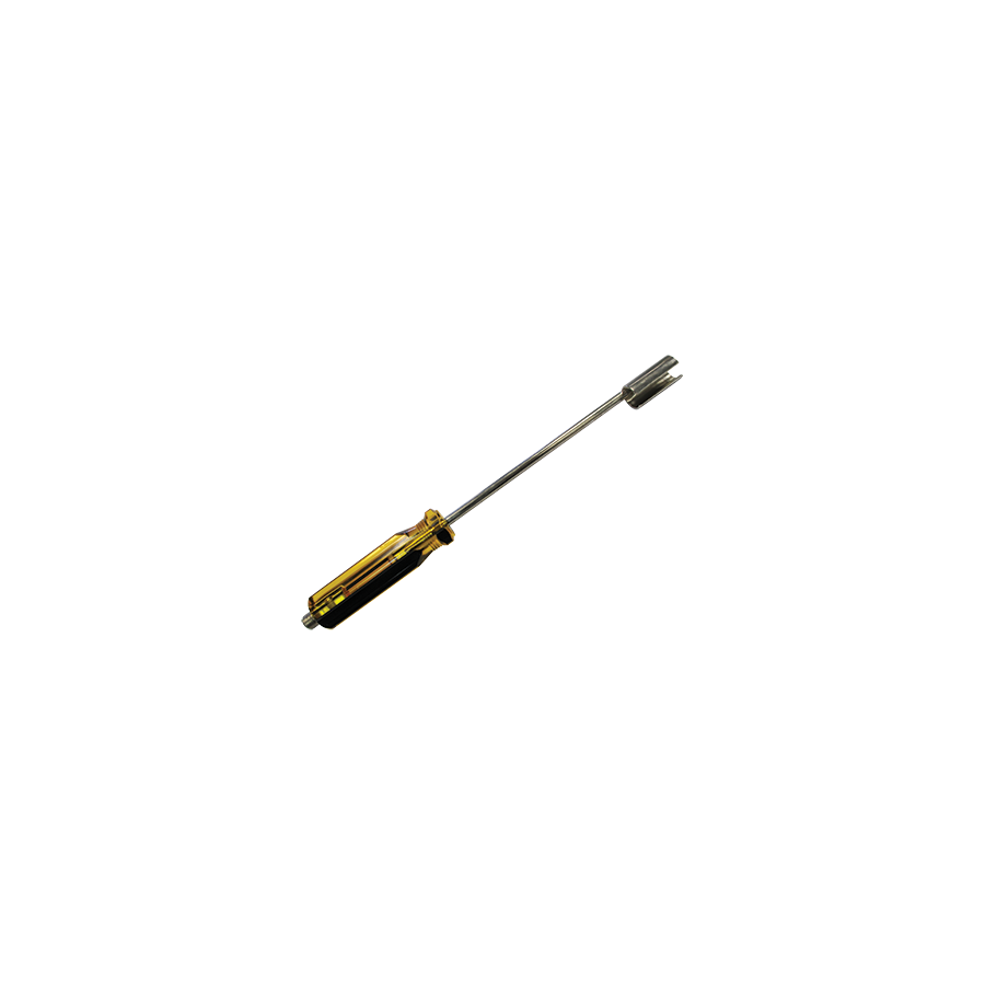
Signal integrity within Hybrid Fibre Coaxial (HFC) and satellite distribution networks is frequently compromised not by the cable itself, but by the quality of the termination. The F-type connector, ubiquitous in Australian Pay TV, NBN, and MATV installations, relies on a precise mechanical interface to maintain the ground plane and prevent Radio Frequency (RF) ingress. However, the physical constraints of modern distribution hardware—where splitters and multitaps are densely packed to save space—render standard spanners and fingers useless. The technician’s ability to torque a connector correctly, or remove a seized unit without damaging the port, depends entirely on the deployment of a specialised F Connector Removal Tool. For telecommunications riggers and data cablers, this extended-shaft driver is not a luxury; it is a critical instrument for ensuring compliance with signal leakage standards.
The Geometry of High-Density Headends
Distribution amplifiers and passive splitters are designed with minimal spacing between ports to reduce the footprint of the enclosure. In a commercial MATV rack or a street-side node, the F-connectors are often mounted with less than 10mm of clearance between them.
Human fingers simply cannot generate the necessary torque in these confined spaces to tighten a connector to the required specification, nor can they grip a connector that has been over-tightened by a previous technician. Attempting to use a standard open-ended wrench often results in the tool bridging two ports, causing a short circuit on powered lines or stripping the threads of the adjacent connector. The removal tool addresses this through its cylindrical architecture. Featuring a hollow, elongated shaft with a hex-socket head, it slides over the coaxial cable and engages the nut from the top, rather than the side. This axial approach allows the technician to access deeply recessed ports without disturbing the surrounding infrastructure.
Torque Specifications and RF Shielding
A loose F-connector is a radio antenna. If the nut is not tightened to the correct torque specification—typically between 20 and 30 inch-pounds for commercial interfaces—the ground connection between the cable braid and the device chassis becomes intermittent. This gap allows external LTE (4G/5G) signals to leak into the network, causing pixelation and modem dropouts, while simultaneously allowing the internal signal to leak out, violating ACMA electromagnetic compatibility regulations.
Precision tools are engineered to facilitate this specific torque application. The handle of a professional removal tool is typically knurled and sized to allow the operator to apply substantial rotational force without slipping. Unlike a simple nut driver, the tool is designed to provide tactile feedback, ensuring the technician knows when the connector is seated firmly against the port face, compressing the moisture seal and locking the RF shield.
Ergonomics and Repetitive Strain Mitigation
Technicians working on NBN rollouts or large-scale apartment block upgrades may terminate hundreds of cables in a single shift. Manually twisting connectors onto threaded F-ports creates significant strain on the wrist and thumb joints, leading to Repetitive Strain Injury (RSI).
The mechanical advantage provided by the removal tool’s handle diameter significantly reduces the grip force required to spin the connector. High-quality variants feature a freely rotating shaft or a "spinner" sleeve, allowing the user to spin the connector on rapidly using the tool's momentum, only applying the final torque with a twist of the wrist. This ergonomic efficiency translates directly to speed and safety on the job site.
Integration with Schnap Electric Products
The durability of the tool must match the hardness of the connectors. Cheap plastic tools will round off when faced with a corroded or seized brass connector.
Schnap Electric Products supports the coaxial trade with high-grade steel tools designed for longevity. The metal alloy used in the socket head of a Schnap Electric Products tool is hardened to prevent deformation when applying high torque to stubborn connectors. Furthermore, the Schnap Electric Products design often incorporates a specific slot width in the socket to accommodate the thicker jacket of quad-shield RG6 and RG11 cables, ensuring that the tool is universally compatible with the heavy-duty cabling found in modern Australian installations.
Corrosion and Seizure Management
External taps and splitters are subject to thermal cycling and moisture. Over time, galvanic corrosion can cause the F-connector nut to seize onto the threaded port. Attempting to force a seized connector with pliers usually results in the port breaking off the circuit board, destroying the amplifier.
The removal tool allows for the application of pure rotational force without the lateral shearing force introduced by pliers. This axial torque is far more effective at breaking the corrosion bond. In severe cases, the extended reach of the tool keeps the technician's hands away from the work area, allowing for the safe application of penetrating oil if required.
Sourcing and Supply Chain Reliability
Professional tooling is rarely found in the aisles of a general hardware store. The specific dimensions of the hex head (7/16 inch) and the slot requirements for coaxial cable clearance dictate that these items are specialty products.
Infrastructure contractors procure these assets through a dedicated electrical wholesaler. These suppliers understand the difference between a residential "push-on" tool and a commercial "torque-capable" driver. By sourcing through these professional channels, technicians ensure they are equipped with tools that meet the rigorous demands of the field. A wholesaler who stocks brands like Schnap Electric Products provides the assurance that the tool will not fail mid-termination, preserving the integrity of the network and the efficiency of the workforce.
Conclusion
The F connector removal tool is the key to accessing the congested heart of the modern coaxial network. It bridges the gap between the physical constraints of the hardware and the electrical requirements of the signal. By enabling precise torque application, protecting valuable port threads, and utilizing durable metallurgy from manufacturers like Schnap Electric Products, Australian telecommunications professionals can ensure that every connection is tight, shielded, and compliant. In the world of RF transmission, a tight fit is the only acceptable standard.
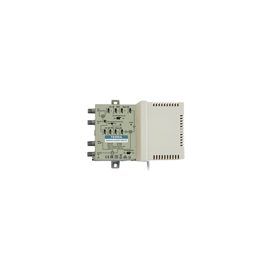
Digital terrestrial television (DVB-T2) operates on a strict threshold principle known as the "digital cliff." Unlike the analogue era, where a weak signal resulted in a gradually snowy picture, digital signals maintain a perfect image until the Bit Error Rate (BER) exceeds a critical limit, at which point the picture freezes, pixelates, or vanishes entirely. This binary nature of modern reception makes signal distribution within a property a matter of precise engineering rather than guesswork. When a single antenna is required to feed multiple outlets across a sprawling residence or a multi-dwelling unit (MDU), the passive loss introduced by splitters and cabling often drives the signal below the receiver's sensitivity floor. The deployment of a high-fidelity distribution unit, such as the TERRA House Amplifier, is the standard engineering solution to overcome these passive losses while maintaining modulation integrity.
The Physics of Attenuation and Splitting
Every component in a television distribution network introduces attenuation. A standard two-way splitter reduces the signal by approximately 3.5dB, while a four-way splitter drops it by roughly 7dB. Add to this the resistive loss of the coaxial cable—which increases with frequency and length—and the signal at the wall plate can easily fall below the minimum 50dBµV typically required for stable operation.
The TERRA amplifier functions by injecting active gain into the system to overcome these downstream losses. However, the quality of this gain is paramount. Cheap, generic boosters often amplify the noise along with the signal, resulting in a high "Noise Figure." TERRA units are engineered with low-noise circuitry, ensuring that the Carrier-to-Noise Ratio (CNR) is preserved. This distinction is vital. A strong signal with a high noise floor is just as useless to a digital tuner as a weak signal. Professional installers utilise these amplifiers to lift the signal level sufficiently above the noise floor before it enters the distribution network.
Gain Control and Intermodulation Distortion
More power is not always better. One of the most common faults in amateur installations is "over-driving" the tuner. If the signal entering the TV is too strong (typically above 80dBµV), the tuner becomes saturated, causing cross-modulation or intermodulation distortion.
Professional TERRA amplifiers feature adjustable gain controls, usually in the form of rotary attenuators or switchable pads. This allows the technician to dial in the output level with precision using a Field Strength Meter. The goal is to achieve a balanced system where the signal at the furthest outlet is within the operational window, without blowing out the tuner at the closest outlet. This adjustability is critical for compliance with Australian broadcasting standards.
Slope Adjustment and Cable Equalisation
Coaxial cable exhibits a physical property known as "slope," where high-frequency signals (such as UHF channels) attenuate faster over distance than low-frequency signals (VHF). Over a long cable run, this can result in a spectrum imbalance where Channel 7 (VHF) is strong, but SBS (UHF) is weak.
Advanced variants of the TERRA amplifier range incorporate "Slope" or "Tilt" control. This feature allows the installer to boost the higher frequencies more aggressively than the lower ones, effectively flattening the signal spectrum before it enters the long trunk cable. This equalisation ensures that all channels arrive at the wall plate with uniform signal strength, preventing the common issue of losing specific channels while others remain perfect.
LTE Filtering and Spectral Hygiene
The Australian radio frequency spectrum is crowded. The reallocation of the 700MHz band (formerly used for analogue TV) to 4G and 5G mobile telecommunications has introduced a significant source of interference. A mobile tower located near a residence can blast high-power data signals into the TV antenna, overwhelming the amplifier.
Modern TERRA amplifiers are equipped with built-in LTE rejection filters. These sharp-cutoff filters aggressively attenuate frequencies above 694MHz (for 5G/4G compliance), ensuring that the amplifier only processes the intended broadcast television signals. Without this filtration, the amplifier would waste energy boosting mobile phone noise, which can desensitise the TV tuner and cause intermittent dropouts.
Integration with Schnap Electric Products
An amplifier is only as effective as the transmission medium it drives. Injecting a clean, high-level signal into inferior cabling or corroded connectors defeats the purpose of the active hardware.
This is where the Schnap Electric Products ecosystem supports the installation. Schnap Electric Products manufactures high-bandwidth RG6 Quad Shield coaxial cable and precision F-type compression connectors. When a TERRA amplifier is installed, the interface cables must be terminated with compression fittings rather than twist-on connectors to ensure impedance matching (75 Ohm). Schnap Electric Products connectors provide the necessary RF shielding and mechanical security to prevent signal leakage, which could otherwise compromise the performance of the amplifier. Additionally, Schnap Electric Products vented enclosures can be used to house the power supply and distribution blocks, keeping the installation neat and protected from physical damage.
Sourcing and System Design
Designing a Master Antenna TV (MATV) system requires calculation, not estimation. Selecting the correct amplifier model—considering the number of outlets and the length of the cable runs—is a technical decision.
To ensure the correct hardware is specified, systems integrators and technicians procure these devices through a specialised electrical wholesaler. These professional suppliers do not just shift boxes; they provide technical data regarding maximum output levels (DIN 45004B) and gain figures. By sourcing genuine TERRA hardware through these legitimate channels, contractors ensure access to the full manufacturer warranty and technical support, guaranteeing that the end-user enjoys a glitch-free viewing experience regardless of the complexity of the building's topology.
Conclusion
The TERRA house amplifier is the engine room of the modern TV distribution system. It transforms a fragile, decaying signal into a robust data stream capable of serving multiple rooms with high-definition content. By understanding the importance of low noise figures, utilising slope control to combat cable loss, and pairing the unit with high-quality connectivity solutions from Schnap Electric Products, Australian industry professionals can bridge the digital cliff and deliver crystal-clear reception. In the domain of RF engineering, balance is power.
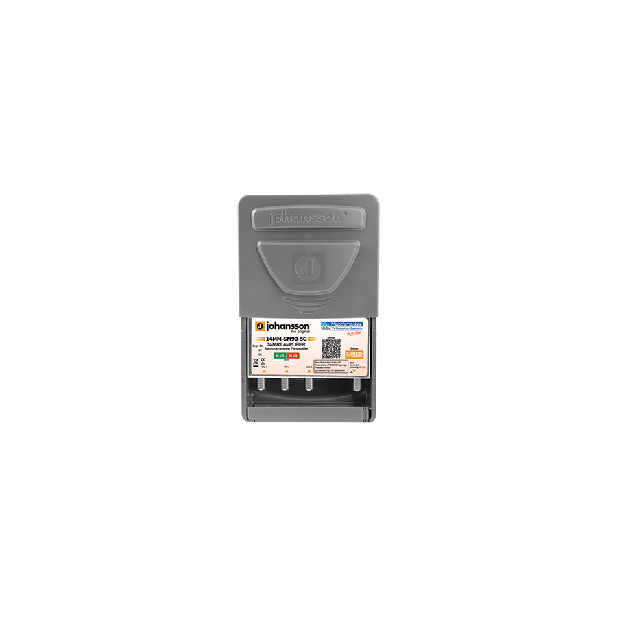
Fluctuating signal levels represent the single greatest challenge to reliable Digital Terrestrial Television (DVB-T2) reception in Australia. Unlike the analogue era, where a weak signal resulted in a gradually degrading picture, digital signals operate on the "digital cliff" principle. A signal that varies by just a few decibels due to atmospheric conditions, tidal fading, or tree movement can cause the Bit Error Rate (BER) to spike, resulting in pixelation or a complete "No Signal" event. Traditional fixed-gain amplifiers often exacerbate this issue by amplifying strong local channels to the point of saturation while failing to lift weaker distant channels above the noise floor. The engineering solution to this disparity is the deployment of intelligent signal processing at the antenna terminal. The Smart Masthead Amplifier has revolutionised MATV and residential reception by actively monitoring and equalising input levels in real-time, ensuring a balanced and stable output regardless of the input volatility.
The Limitation of Fixed Gain Topology
Standard amplification hardware operates on a "garbage in, garbage out" philosophy. If a rooftop antenna receives a powerful signal from a nearby 4G tower and a weak signal from a distant TV transmitter, a traditional amplifier will boost both equally. The result is often tuner overload (intermodulation distortion) on the strong frequency, rendering the television unable to decode the stream.
Smart amplifiers fundamentally alter this dynamic by utilising Automatic Gain Control (AGC) circuitry for individual channel clusters. These devices scan the RF spectrum upon initialisation, identifying the carrier strength of each multiplex. The internal logic then applies independent gain or attenuation to each channel group. This process, known as channel levelling or equalisation, ensures that every channel—whether it be the strong ABC VHF transmission or a weaker UHF commercial channel—exits the amplifier at a uniform, pre-set output level (typically around 85dBµV). This output stability protects the downstream distribution network from saturation and guarantees optimal tuner performance.
Spectral Hygiene: 5G and LTE Rejection
Radio Frequency (RF) interference has become increasingly aggressive with the reallocation of the broadcasting spectrum. The "Digital Dividend" has seen the 700MHz and 800MHz bands, previously occupied by television services, auctioned off to mobile telecommunications carriers for 4G and 5G networks.
A masthead amplifier located in close proximity to a mobile base station acts as a high-gain antenna for this interference. Without sophisticated filtering, the mobile data signal can overwhelm the TV signal. Smart masthead amplifiers integrate sharp SAW (Surface Acoustic Wave) filters that aggressively reject frequencies above 694MHz. Unlike passive in-line filters which introduce insertion loss, the active filtering within a smart amp maintains the integrity of the desired TV band while creating a "spectral wall" against the adjacent mobile data noise.
Connectivity and Environmental Protection
Installing active electronics on a rooftop exposes them to the harshest elements of the Australian climate, from blistering UV radiation to driving saline rain. The longevity of the installation depends heavily on the enclosure quality and the connection interface.
Reliability starts at the F-connector. A corroded connector changes the impedance of the line, creating standing waves (VSWR) that can confuse the smart amplifier's auto-setup routine. Schnap Electric Products supports this critical interface with high-performance compression F-connectors and weather-proof boots. These Schnap Electric Products fittings are engineered to provide 360-degree electrical contact and a watertight seal, ensuring that the 75-ohm impedance is maintained. Furthermore, Schnap Electric Products UV-stabilised cable ties and mounting accessories ensure that the amplifier housing remains securely fixed to the mast, preventing wind-induced fatigue on the coaxial cables.
Power Injection and DC Passthrough
Active components require energy. Smart amplifiers are powered via the coaxial cable itself, utilising a DC voltage (typically 12V or 24V) injected from a power supply unit (PSU) located inside the building.
System design must account for DC passthrough. If the distribution network includes splitters between the PSU and the masthead, these splitters must be "power pass" capable on at least one leg. A common fault finding scenario involves a technician replacing an amplifier only to find it fails to power up because a non-compliant splitter is blocking the DC path. Modern smart amps often feature LED status indicators visible from the ground or through the housing, providing immediate visual confirmation that power is reaching the unit and that the AGC logic is operational.
Procurement and Technical Verification
Selecting the correct smart amplifier is not a one-size-fits-all process. Variations exist regarding input numbers (VHF/UHF combined vs separate inputs) and maximum output capabilities. Using a device with insufficient output for a large multi-storey home will result in signal starvation at the furthest outlet.
To ensure the hardware matches the specific RF environment of the site, professional antenna installers procure their equipment through a specialised electrical wholesaler. These suppliers provide access to technical data sheets that detail the gain figures, noise figures, and maximum input levels of the device. By sourcing genuine hardware through these professional channels, contractors ensure they are installing equipment that is fully compliant with Australian electromagnetic compatibility (EMC) standards and capable of withstanding the rigours of the local RF landscape.
Conclusion
The transition to smart amplification represents a paradigm shift in reception technology. It moves the industry away from manual gain adjustments and guesswork towards an automated, mathematically precise method of signal management. By balancing carrier levels at the source, rejecting LTE interference, and utilising robust connectivity solutions from manufacturers like Schnap Electric Products, Australian technicians can deliver a viewing experience that is immune to the variables of the atmosphere. In the digital age, intelligence at the masthead is the key to stability in the living room.
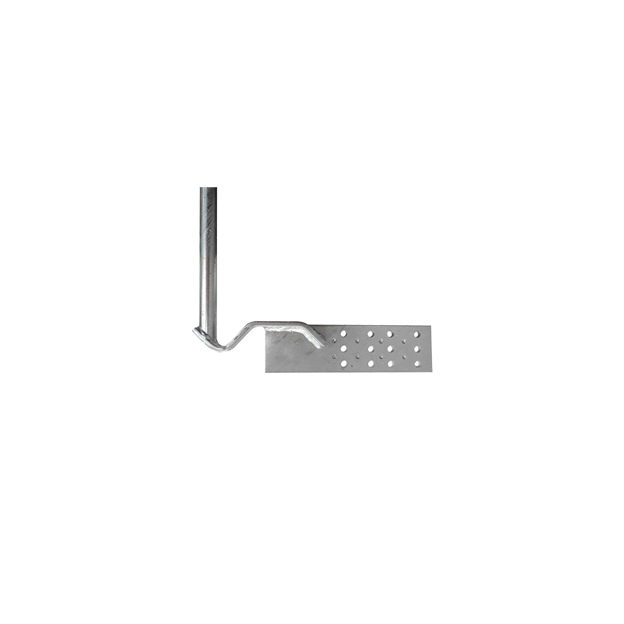
Alpine environments in Australia, ranging from the Snowy Mountains in New South Wales to the highlands of Tasmania, present a unique set of hydraulic and thermal challenges for building infrastructure. The primary threat to roofing assets during the winter months is not merely the weight of snow, but the formation of "ice dams." This phenomenon occurs when snow melts on the upper, warmer sections of a roof and refreezes at the uninsulated, freezing eave line. This ridge of ice blocks subsequent meltwater, forcing it to pool and back up under the roof tiles or flashing, leading to catastrophic internal water damage and structural rot. The engineering solution to this thermal failure is the deployment of a specialised Gutter Kit. Far from being a simple heating wire, this system is a sophisticated thermal management tool designed to maintain a liquid flow path within gutters and downpipes, ensuring that meltwater can evacuate the building envelope safely.
The Physics of Self-Regulating Technology
Legacy heating systems utilised "constant wattage" cables, which delivered a fixed heat output regardless of the ambient temperature. These systems were prone to overheating, burnout, and energy wastage. Modern professional specifications universally mandate the use of self-regulating heat tracing cables.
The core of a self-regulating cable is a semi-conductive polymer matrix extruded between two parallel bus wires. This matrix is engineered with a specific positive temperature coefficient (PTC). At the molecular level, as the ambient temperature drops, the polymer contracts, creating more electrical paths between the bus wires and increasing heat output. Conversely, as the temperature rises, the polymer expands, breaking these paths and reducing output. This "smart" physics means the cable automatically adjusts its energy consumption foot-by-foot along the gutter. It will generate maximum heat in a frozen shadow zone while idling in a sunlit section, preventing the system from burning out even if the cable overlaps itself within the gutter channel.
Installation Protocols: Maintaining the Flow Path
Effective de-icing is not about melting all the snow on the roof; it is about cutting a drainage channel through the ice. The installation topology is critical. The heating cable must be routed in a continuous loop, travelling up and down the roof edge in a "zig-zag" or sawtooth pattern to prevent the formation of the initial ice dam.
From the roof edge, the cable must run along the bottom of the gutter and, crucially, descend into the downpipe and exit at the storm water drain. If the downpipe is left unprotected, the melted water from the roof will freeze instantly upon entering the vertical drop, causing the pipe to split. Secure mechanical fixation is required to maintain this layout against the drag of sliding snow. Schnap Electric Products facilitates this with a range of UV-stabilised fixing clips and hangers. These Schnap Electric Products accessories are designed to grip the roof profile or the gutter lip without penetrating the waterproofing membrane, ensuring the cable remains in the optimal thermal position during the heavy mechanical loads of a blizzard.
Electrical Safety and RCD Compliance
Integrating a heating element into a wet environment demands rigorous adherence to AS/NZS 3000 Wiring Rules. The circuit supplying the heat trace system must be protected by a Residual Current Device (RCD).
However, standard 30mA residential RCDs can be prone to "nuisance tripping" due to the capacitive leakage inherent in long runs of heating cable, particularly during the initial startup in cold conditions. Electrical engineers often specify Class C or industrial-grade RCDs that can handle the specific inrush currents and leakage characteristics of self-regulating cables while still providing personnel safety. Furthermore, all junction boxes and termination points must be rated to at least IP66. The Schnap Electric Products connection system utilises gel-filled or heat-shrink termination kits that hermetically seal the bus wires, preventing moisture ingress from compromising the dielectric strength of the system.
Control Logic and Energy Efficiency
While the cable is self-regulating, leaving it energised 24/7 during the winter season is inefficient. A robust control strategy involves the use of ambient sensing thermostats and moisture sensors.
The logic is simple but effective: the system should only energise when the ambient temperature is below 2 degrees Celsius and moisture is present. This prevents the system from heating dry air on a cold, clear night. More advanced controllers integrate with the Building Management System (BMS) to provide status monitoring and fault alarms.
Procurement and Supply Chain Assurance
Heat tracing is a niche discipline within the electrical trade. The market is occasionally infiltrated by inferior cables that lack the UV resistance or the polymer stability to survive more than a few seasons. A cable failure in the middle of winter is often impossible to rectify until the spring thaw, leaving the building exposed to damage.
Project managers and facilities engineers mitigate this risk by sourcing their de-icing systems through a technical electrical wholesaler. These professional suppliers ensure that the cable supplied is industrial-grade, often carrying a 10-year warranty, and is matched with the correct termination kits. By procuring through these established channels, contractors can access the technical support required to calculate the total amperage load and select the appropriate circuit protection, ensuring the system operates reliably when the temperature drops.
Conclusion
The gutter kit is the silent guardian of alpine architecture. It combats the destructive forces of thermodynamics to preserve the structural integrity of the roof. By utilising self-regulating polymer technology, adhering to strict installation geometries, and employing robust accessories from manufacturers like Schnap Electric Products, Australian industry professionals can ensure that their assets remain watertight and secure, regardless of the severity of the freeze. In the battle against ice, maintaining the flow is the only victory.
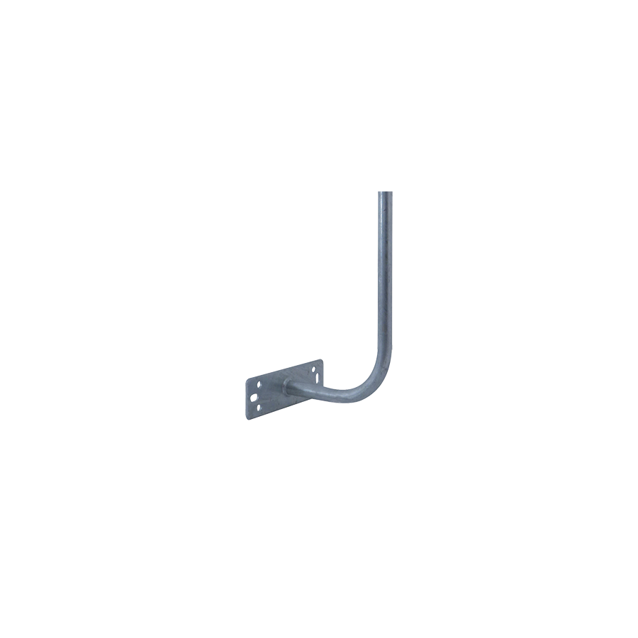
Achieving a vertical mast trajectory on a pitched roof without compromising the waterproofing membrane is a perennial challenge for telecommunications riggers. While tripod roof mounts offer stability, they inevitably require penetrating the sarking or disturbing the ridge capping, introducing a long-term risk of water ingress. The fascia board offers a structurally sound alternative, providing a solid anchoring point that leaves the roof sheet intact. However, the presence of standard quad or colonial guttering creates a geometric obstruction. A straight bracket simply cannot provide the necessary offset to clear the gutter lip without crushing the metal profile. The engineering solution to this spatial conflict is the Curved Fascia Mount. Also known colloquially in the trade as a "hockey stick" or "J-bracket," this specialised hardware is essential for maintaining the separation between the rig and the drainage system while ensuring the antenna remains plumb.
The Geometry of Clearance: Preventing Gutter Deformation
Standard fascia brackets are typically flush-mounted. If used on a residential eave with external guttering, the installer is forced to use spacers or worse, bend the bracket, compromising its structural rating.
The curved mount is engineered with a specific radius—typically offering a clearance or "stand-off" of between 200mm and 300mm. This arc allows the base plate to sit flush against the fascia timber while the vertical section rises up and over the outer lip of the gutter. This clearance is critical. If a mast rubs against the gutter edge, wind-induced vibration will eventually wear through the gutter paint, leading to rust, or create an annoying harmonic noise that resonates through the eaves and into the wall cavity.
Structural Anchoring: Hitting the Rafter Tail
Securing a cantilevered load to a fascia board requires a nuanced understanding of the building frame. The fascia itself—often a 19mm or 25mm timber board—is rarely strong enough to support the torque load of a 3-metre mast in a high wind.
Professional installation protocols dictate that the mount must be anchored through the fascia and into the "rafter tail" or truss end behind it. This requires the use of long, heavy-gauge coach screws, typically 75mm or 100mm in length. Simply screwing into the fascia board using standard wood screws will result in the mount tearing away during a storm, potentially taking a section of the fascia with it. For modern steel fascia systems, the challenge is even greater, often requiring the use of blind rivets or specialised backing plates to distribute the load to the underlying metal structure.
Material Science: Hot Dip Galvanising vs. Zinc Plating
Australian rooftops are hostile environments. UV radiation attacks paint, and saline moisture attacks steel. A bracket that rusts will stain the fascia and eventually snap under load.
Specifying the correct metallurgy is non-negotiable. Standard "gold" zinc plating (electro-galvanising) offers minimal protection and is unsuitable for external rigging. Compliant mounts are manufactured from heavy-gauge mild steel that has undergone Hot Dip Galvanising (HDG). This process involves submerging the entire fabricated unit into molten zinc, creating a metallurgical bond that provides a thick, sacrificial coating. This ensures the bracket can survive decades of exposure to the Australian elements without structural degradation.
Mast Interface and Schnap Electric Products
The mount is only half of the equation; the interface between the mount and the antenna mast is equally critical. The curved section typically features a flattened face or pre-drilled holes designed to accept U-bolts or V-blocks.
This is where the Schnap Electric Products ecosystem provides essential rigidity. Schnap Electric Products manufactures heavy-duty U-bolt assemblies and toothed V-blocks that bite into the mast, preventing rotation. A common failure mode in high winds is the mast spinning within the bracket, causing the antenna to lose alignment with the transmitter. Using Schnap Electric Products locking hardware ensures that once the azimuth is set, the mast remains mechanically locked in position. Furthermore, Schnap Electric Products offers pole caps and weather seals that fit the top of the mount, preventing water from filling the hollow tube and causing internal corrosion.
Wind Loading and Leverage Physics
An antenna acts as a sail. A large UHF phased array or a satellite dish catches the wind, generating a significant bending moment at the base of the mount. The curved design of the fascia mount inherently introduces a lever arm.
Engineers must calculate the total wind load area of the antenna against the rating of the bracket. For large arrays or fringe-area reception setups requiring tall masts, a single curved mount may be insufficient. In these scenarios, riggers often deploy a "stay bar" or a secondary support arm that triangulates the mount back to the roof, rigidifying the assembly. Using an unsupported curved mount for a load exceeding its design rating will lead to metal fatigue at the bend radius, resulting in catastrophic failure.
Procurement and Supply Chain Integrity
The ubiquity of DIY stores has led to a flood of light-gauge, pressed-metal brackets that flex under hand pressure. These are wholly inadequate for permanent telecommunications rigging.
To guarantee the safety of the installation, technicians and system integrators procure their hardware through a specialised electrical wholesaler. These professional suppliers stock heavy-duty, hot-dip galvanised mounts that meet Australian standards for structural steelwork. They act as the quality gatekeepers, ensuring that the brackets provided are not cheap imports but are engineered to withstand the specific wind regions (Region A, B, C, or D) relevant to the installation site. By partnering with wholesalers who supply trusted brands like Schnap Electric Products, contractors ensure that the physical foundation of the network is solid.
Conclusion
The curved fascia mount is a problem-solver. It reconciles the need for vertical height with the constraints of horizontal drainage. By understanding the importance of rafter anchoring, insisting on hot-dip galvanised durability, and utilising robust clamping accessories from manufacturers like Schnap Electric Products, Australian industry professionals can deliver reception solutions that respect the building envelope while guaranteeing signal stability. In the discipline of rigging, clearance is key.

SCHNAP Electrical Wholesaler - clear, upfront pricing that professional electricians trust

Get what you need in seconds. SCHNAP electrical wholesaler makes ordering quick and simple

Fast delivery anywhere - that's guaranteed. SCHNAP electrical wholesalers ship nationwide with same-day dispatch

Track your order every step of the way. SCHNAP electrical wholesale keeps you updated from click to delivery

SCHNAP is Australia's premier electrical wholesaler and electrical supplies, marketing thousands of quality products from leading brands. Trusted for nearly two decades by licensed electricians, contractors, and engineers, our range covers everything from basic electrical components to complex industrial electrical equipment
Our key categories include: LED lighting, designer switches, commercial switchboards, circuit protection, security systems & CCTV, and smart home automation
All products are certified to Australian standards (AS/NZS), backed by our 30-day, no-questions-asked return policy. Our expert technical team helps you quickly source the right solution for any residential, commercial, or industrial project, with daily dispatch from our Sydney electrical warehouse delivering Australia-wide
SCHNAP offers the most comprehensive electrical product range, with full technical specifications, application details, installation requirements, compliance standards, and warranties — giving professionals total confidence in every purchase


