




Kingsgrove Branch:
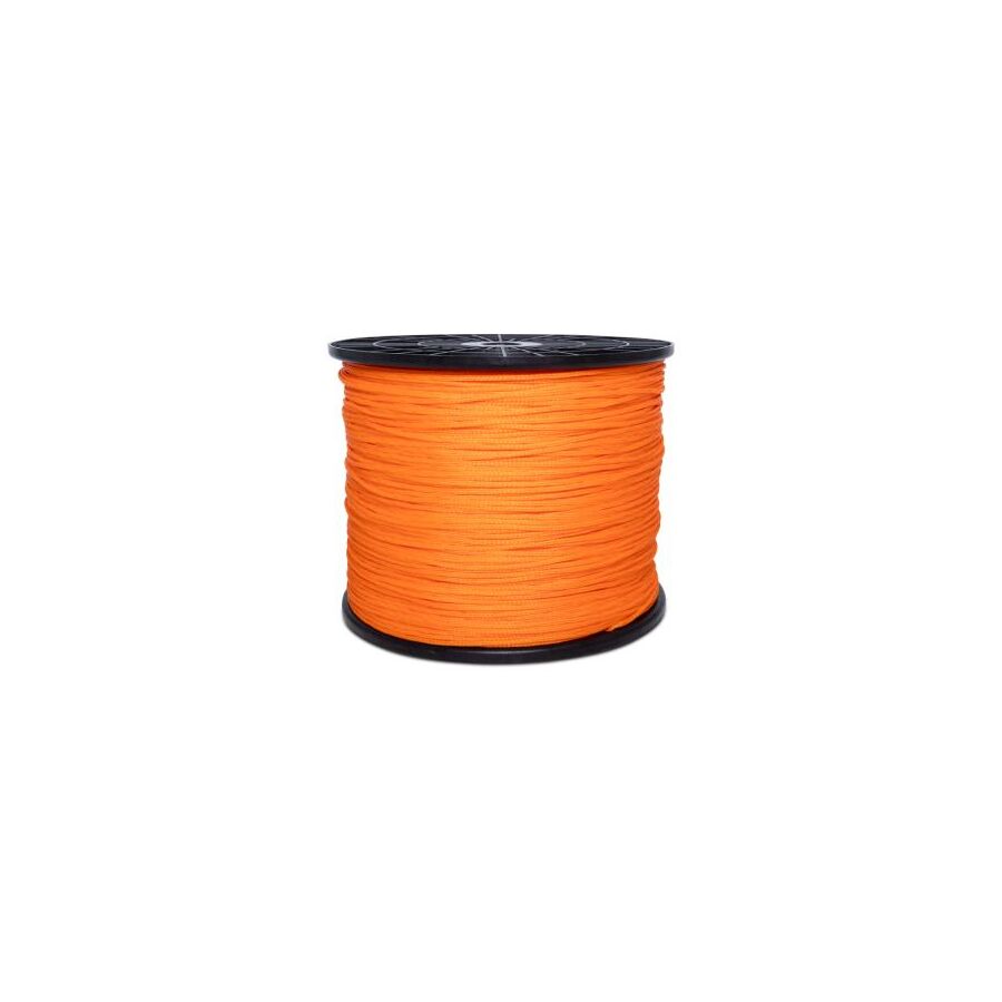
Across Australia’s underground electrical and telecommunications infrastructure, every successful cable installation begins with a single mechanical link. Before heavy copper feeders, fibre optic backbones, or control cables can be installed, a pilot path must be established through the conduit system. This requirement is most critical in long-distance pit and pipe networks, congested duct banks, and waterlogged civil environments where rigid fibreglass rods lose effectiveness due to friction and limited flexibility. The industry-accepted solution is the Pull Line Rope. This specialised cordage provides a continuous, high-tensile connection between pits, enabling the controlled introduction of hauling ropes or lightweight cables. Its selection is dictated by material science, tensile physics, and deployment method, as failure inside a conduit can result in costly delays and re-excavation.
Underground conduit systems are rarely clean or dry. In Australian civil conditions, conduits are commonly filled with groundwater, silt, clay, and organic matter. Natural fibre strings absorb moisture, swell, and degrade rapidly, making them unsuitable for any professional cabling work.
Professional pull line ropes are manufactured from virgin Polypropylene or high-density Polyethylene. These polymers are hydrophobic, meaning they do not absorb water. As a result, the line maintains a consistent weight and handling characteristic regardless of conduit conditions. This property is critical during long pulls where additional mass increases friction and tension.
Polypropylene also offers excellent resistance to rot, mildew, and most industrial chemicals. This makes it suitable for mining, wastewater, and industrial precincts where soil conditions may be acidic or alkaline. The fibrillated structure of high-quality pull lines allows the rope to flatten slightly under tension, spreading load and reducing abrasive contact against conduit walls during high-load hauling.
For long conduit runs, pneumatic installation remains the most efficient deployment method. Often referred to as blow-through installation, this technique uses a foam piston attached to the pull line, propelled by high-volume airflow from an industrial blower.
The success of this method depends on the rope’s strength-to-weight ratio. The pull line must be light enough to remain airborne within turbulent airflow while strong enough to resist abrasion and unspooling forces at high speed. Excessive mass or surface drag causes the piston to stall, particularly in conduits with multiple sweeps.
Professional pull line rope is packaged to eliminate spiral memory. Centre-pull buckets and dispenser boxes allow the line to feed smoothly without tangling or knotting. This controlled dispensing is critical during pneumatic installation, where sudden resistance can snap the line or lodge the piston inside the duct, forcing a full system reset.
Although primarily a pilot line, the pull line rope is frequently used to draw heavier hauling ropes or directly install lightweight cables. For this reason, tensile strength is a non-negotiable specification.
Pull line ropes are rated by breaking strain, typically ranging from 40 kg for data and communications conduits to more than 200 kg for civil and power applications. Selecting an undersized line introduces significant risk. If the line breaks during a pull, recovery is often impossible without re-roding or re-blowing the entire conduit length.
Professional lines are often colour-coded or tracer-marked to identify their tensile rating at a glance. This allows supervisors and installers to verify that the correct line is being used for the distance, conduit size, and expected load, reducing the likelihood of failure under tension.
Friction is the primary enemy of successful cable hauling. Every conduit bend introduces resistance, and over long distances this resistance compounds rapidly. As tension increases, friction generates heat that can soften polymer rope or damage conduit walls.
To mitigate this, installers frequently use cable lubricants during hauling operations. Compatibility between the pull line material and the lubricant is essential to prevent chemical degradation. Polypropylene performs well with common water-based and polymer-based lubricants used in Australian infrastructure projects.
The pull line is also used to run cleaning mandrels and conduit scourers prior to cable installation. This preparation step removes debris and standing water, reducing friction and protecting the final cable sheath during the pull.
The performance of a pull line rope is closely tied to the quality of the conduit it operates within. Smooth internal bore finishes significantly reduce drag and improve hauling reliability.
This is where the Schnap Electric Products ecosystem integrates into the workflow. Schnap Electric Products manufactures rigid and flexible conduit systems designed with consistent internal diameters and smooth bore profiles. When used in conjunction with high-quality pull line rope, these conduits allow the line to glide with minimal resistance, reducing tension spikes during hauling.
Schnap Electric Products also supplies draw springs, conduit accessories, and cable grips that attach securely to the pull line. These components ensure that force transfer from pilot line to hauling rope or cable is controlled and evenly distributed, preventing sheath damage and connector failure.
On large infrastructure projects, logistics matter as much as performance. Running out of pull line mid-installation halts work immediately and can delay entire project schedules.
Professional pull line rope is supplied in robust packaging, typically coils or buckets ranging from 500 m to 3000 m. These containers are designed to survive transport in service vehicles, exposure to mud, and repeated handling on site. UV stabilisation is also critical, as lines are often stored outdoors before deployment.
Electrical wholesaler play a key role in supply reliability. By sourcing pull line rope through specialised distributors, contractors gain access to certified products with consistent tensile ratings and batch testing. A reputable wholesaler also ensures availability of complementary Schnap Electric Products accessories, allowing installers to complete pulling operations without interruption.
Pull line rope operates under significant tension during hauling. Sudden release caused by line failure can result in whiplash injuries or damage to equipment.
Installers must ensure the rope is rated for the intended load and that attachment knots or grips are correctly installed. Clear communication between pit crews is essential during pulling operations, and tension should be applied gradually to identify obstructions before catastrophic failure occurs.
Using a correctly specified pull line reduces these risks and contributes to a safer, more predictable installation process.
The pull line rope is the foundation of every successful underground cabling project. It establishes the pathway that allows power, data, and control systems to be installed efficiently and safely. By selecting hydrophobic, high-tensile materials, matching break ratings to application demands, and integrating the rope with smooth-bore conduit systems from manufacturers such as Schnap Electric Products, Australian industry professionals can eliminate unnecessary delays and reduce installation risk. In the science of connectivity, the strength of the first line determines the success of everything that follows.
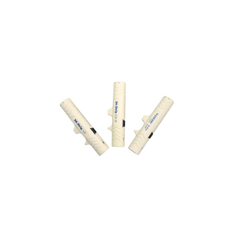
The rapid expansion of rooftop photovoltaic systems across Australia has transformed solar installation into a core electrical discipline rather than a specialist niche. Modern PV arrays operate in an environment defined by extreme ultraviolet exposure, wide temperature swings, and high-voltage Direct Current (DC). To survive these conditions, solar cabling such as PV1-F and H1Z2Z2-K is manufactured with double-insulated, electron-beam cross-linked polymers that far exceed the toughness of standard building wire. While this construction delivers durability, it introduces a critical challenge at termination. Conventional wire strippers designed for soft PVC insulation are not capable of consistently stripping solar cable without damaging the conductor. The industry-accepted solution is the dedicated Solar Cable Stripper. This precision tool is engineered specifically for cross-linked insulation systems, enabling clean, repeatable stripping that preserves conductor integrity and supports safe, gas-tight DC terminations.
Standard electrical wiring in residential and commercial buildings uses Polyvinyl Chloride insulation. PVC is flexible, relatively soft, and easily severed using compression-based stripping tools. Solar cable insulation is fundamentally different.
PV cable insulation is typically Cross-Linked Polyethylene or a comparable thermoset polymer. During manufacture, the polymer chains are chemically cross-linked using electron-beam irradiation. This process dramatically increases heat resistance, abrasion resistance, and long-term UV stability. As a result, the insulation does not soften when heated and cannot be cleanly removed using crushing or tearing methods. When a standard stripper is used on XLPE insulation, the blades often fail to penetrate evenly, forcing the installer to twist or pull the insulation free. This action stretches the copper strands and leaves uneven insulation edges that compromise connector insertion.
A professional solar cable stripper uses hardened, precision-ground blades that shear through the insulation rather than compressing it. The blade profile is engineered to navigate the dual-layer construction in a controlled motion, producing a clean circumferential cut while leaving the conductor undisturbed.
In DC systems, conductor damage at terminations presents a serious fire risk. Unlike Alternating Current, Direct Current does not pass through a zero-crossing point. Once an electrical arc forms, it is self-sustaining and can reach temperatures capable of igniting roof structures and polymer insulation.
One of the most common causes of series DC arc faults is strand damage during stripping. When copper strands are nicked or partially severed, the effective conductor cross-section is reduced. This creates a localised high-resistance point that heats rapidly under load. In a typical solar string carrying 10 to 15 amps continuously, even minor strand loss can generate sufficient heat to degrade the connector interface.
Solar cable strippers are calibrated for common Australian PV cable sizes, typically 4 mm² and 6 mm². The cutting depth is controlled to micrometre accuracy, penetrating the insulation fully while stopping short of the copper. This ensures that all strands remain intact and capable of carrying the designed current for the full service life of the installation.
Solar connectors rely on precise geometry to maintain electrical performance and environmental sealing. The crimp barrel inside a standard MC4-style connector is manufactured to strict dimensional tolerances.
Incorrect strip length introduces two risks. If the insulation is stripped too short, insulation enters the crimp barrel and prevents full conductor compression. This results in a weak electrical connection. If the insulation is stripped too long, exposed copper extends beyond the contact, reducing creepage distance and increasing the risk of moisture ingress or electric shock.
Professional solar cable strippers incorporate an adjustable strip-length stop. This allows installers to set a consistent length, commonly 10 mm or 12 mm depending on connector design. Consistent strip length ensures uniform crimp quality across an entire array and preserves the IP68 rating of the connector system.
The stripper is the first step in a termination process that continues through connectors, isolators, and combiner equipment. Any error at the stripping stage propagates downstream.
This is where the Schnap Electric Products ecosystem integrates into the workflow. DC isolators and combiner enclosures manufactured by Schnap Electric Products are designed for high-voltage PV systems and rely on precise cable preparation. Their terminal cages and clamping mechanisms assume a cleanly stripped conductor with no insulation residue and no damaged strands. Proper preparation using a dedicated solar stripper allows correct torque application and ensures long-term thermal stability within the enclosure.
Solar installation work is performed in physically demanding conditions, often on pitched roofs and in high ambient temperatures. Tools must minimise fatigue and allow safe operation.
Professional solar cable strippers are lightweight and constructed from glass-fibre reinforced polymers. The cutting mechanism is designed for single-handed operation, allowing the installer to grip the roof or ladder with the other hand. The grip-cut-strip action is completed in one controlled squeeze, reducing repetitive strain and speeding up termination work without sacrificing accuracy.
A tool that requires repeated adjustment or excessive force increases installer fatigue and the likelihood of mistakes. Ergonomic design directly contributes to both safety and productivity on the roof.
Australian photovoltaic installations are governed by AS/NZS 5033, which mandates correct cable preparation and termination to minimise fire risk. Tools that produce inconsistent or damaged strips place the entire installation outside compliance.
The market contains generic multi-purpose stripping tools that claim to handle solar cable but lack the hardened blade geometry required for XLPE insulation. These tools dull quickly and produce variable results.
To ensure compliance and long-term reliability, professional contractors source solar cable strippers through electrical wholesaler. These suppliers stock tools designed and tested specifically for Australian PV cable standards. A reputable wholesaler will also supply compatible crimping tools and test equipment, enabling installers to verify insulation resistance and connector integrity before system commissioning.
The solar cable stripper is a critical safety tool in modern photovoltaic installations. It addresses the unique material challenges of cross-linked insulation and protects conductor integrity in high-current DC systems. By ensuring precise strip length, preserving copper strands, and preparing cables for secure termination into high-quality hardware such as that produced by Schnap Electric Products, Australian solar professionals can build systems that are safe, compliant, and capable of delivering power reliably over decades. In solar engineering, precision at preparation defines performance for the life of the array.
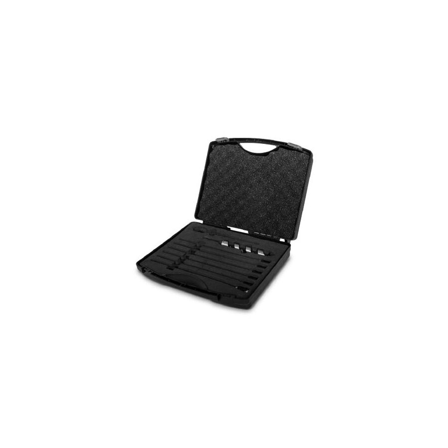
In Australian residential and light commercial construction, retrofit electrical work frequently requires drilling through completed wall cavities rather than open framing. Unlike new builds, where cabling is installed before plasterboard is fixed, renovation projects demand precision drilling through hidden structural members. The primary obstruction in these cavities is the timber frame itself, particularly intermediate noggins and top plates that interrupt vertical cable runs. Standard auger and spade bits, typically limited to 150mm length, are inadequate when the obstruction sits more than a metre above the access point. The professional solution to this spatial limitation is the Woodbit Extension Kit. This modular drilling system extends the effective reach of auger and spade bits, allowing controlled penetration of structural timber from remote access points such as power point cut-outs or roof spaces, without destructive wall removal.
The defining engineering challenge of a drill bit extension is the reliable transmission of torque over a long shaft. When a large auger bit engages dense hardwood or laminated framing, resistance increases dramatically. Any weakness in the extension interface results in slippage, twisting, or shear failure.
Professional woodbit extension kits use a hardened hexagonal shank system, commonly 7/16 inch or 1/4 inch depending on bit size. The hex profile provides positive engagement across six faces, preventing rotational slip under load. Unlike round-shank extensions, which rely on friction alone, hex interfaces maintain alignment and torque integrity even under aggressive cutting forces. The extension rod itself is manufactured from high-tensile alloy steel designed to resist torsional deflection. Inferior extensions behave like torsion springs, storing energy before releasing it unpredictably, increasing the risk of tool failure and operator injury.
One of the most common failure modes during cavity drilling is bit separation. This occurs when the drill is reversed to withdraw the auger and friction within the timber pulls the bit out of the extension, leaving it trapped inside the wall cavity.
To prevent this, professional extension kits use secure locking mechanisms. The most reliable system is the dual grub screw arrangement. Hardened set screws are tightened directly onto the flat faces of the bit shank, creating a mechanical lock that resists axial pull-out. Although this method requires an Allen key, it provides the highest retention strength and is preferred for structural drilling.
Quick-release systems using ball-bearing detents are also available. These offer faster bit changes but must be properly recessed to avoid snagging on insulation or timber fibres during withdrawal. In retrofit environments where access is limited and recovery is difficult, retention strength should always take precedence over speed.
Deep drilling introduces a secondary challenge: waste removal. Auger bits rely on spiral flutes to transport chips out of the hole. When drilling through noggins deep within a cavity, these flutes are often fully embedded in timber, limiting chip clearance.
Packed chips increase friction and heat, leading to bit seizure. Operators must use a controlled pecking technique, withdrawing the bit periodically to clear the flutes. Extension rods are deliberately manufactured with a slightly reduced diameter compared to the cutting head. This clearance prevents the extension from binding against the hole walls and allows debris to move freely along the auger path.
Failure to manage chip evacuation is the most common cause of broken extensions and snapped auger heads in retrofit work.
The purpose of extended drilling is to establish compliant cable pathways through structural timber. Once penetration is achieved, power and data cabling can be routed without breaching wall linings.
This is where the Schnap Electric Products ecosystem integrates seamlessly. After drilling through a top plate using a woodbit extension, electricians typically draw down thermoplastic-sheathed cable or flexible conduit. A clean, accurately aligned hole ensures the cable sheath is not damaged during installation. In external walls, the extension kit may be used to route conduit toward weatherproof outlets or external junction boxes.
Precision drilling ensures compliance with AS/NZS 3000 safe wiring zones, maintaining adequate edge distance from studs and protecting cables from future fastener penetration.
Blind drilling within wall cavities carries inherent risks. Water pipes, gas lines, existing electrical circuits, and structural fasteners may be concealed behind the surface.
Before using a woodbit extension kit, installers must scan the drilling zone using a stud finder capable of detecting metal and live AC voltage. Drilling should only proceed once the path is confirmed clear. Operators must maintain a firm two-handed grip on the drill and use a side handle where available. Long extensions amplify reaction torque if the bit binds on a knot or nail.
Drills fitted with electronic clutch control significantly reduce injury risk. Impact drivers should only be used where the extension kit is explicitly rated for impact torque.
Woodbit extension kits are typically modular, allowing multiple sections to be joined. However, longer assemblies increase torsional stress and vibration. For residential framing, extensions between 300mm and 600mm provide optimal balance between reach and control. Excessive length increases the risk of whip and misalignment.
Extensions should always be matched to the auger or spade bit diameter. Oversized bits on undersized extensions increase shear risk at the coupling point.
The market contains low-grade extension rods manufactured from mild steel or poorly heat-treated alloys. These tools bend, shear, or lose concentricity under load. Failure inside a finished wall often results in plaster removal and costly rectification.
Professional contractors source woodbit extension kits through specialised electrical wholesaler. These suppliers stock extensions rated for high-torque drilling and compatible with Australian-standard auger systems. A reputable wholesaler will also stock cable draw tapes and lubricant, allowing installers to immediately utilise the newly drilled pathway without additional delays.
The woodbit extension kit is a critical enabler of modern retrofit construction. It allows electricians to overcome structural barriers without invasive demolition, preserving finished surfaces while maintaining compliance. By understanding torque transfer mechanics, selecting secure locking systems, and using the tool to install quality infrastructure supported by manufacturers such as Schnap Electric Products, Australian professionals can navigate concealed framing with confidence. In retrofit work, controlled reach defines successful connection.
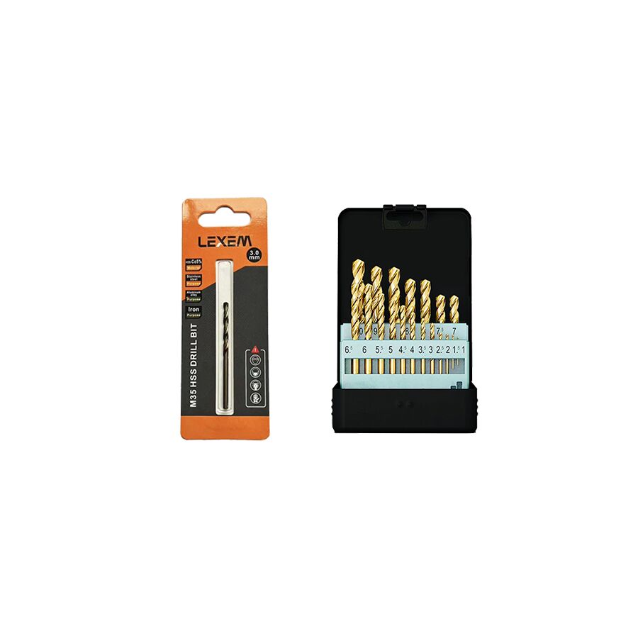
In the heavy engineering and industrial electrical sectors across Australia, the fabrication of switchboards, control panels, and stainless steel enclosures demands tooling that can withstand extreme mechanical and thermal stress. As regulatory standards increasingly specify marine-grade 316 stainless steel for enclosures used in mining, oil and gas, food processing, and wastewater facilities, conventional drilling tools have become a major productivity bottleneck. Standard high-speed steel drill bits lack the thermal stability required for austenitic stainless steels. They overheat, lose edge hardness, and rapidly blunt, often causing work-hardening of the material and irreversible surface glazing. The professional solution to this challenge is the Cobalt Drill Bits Set. Engineered from alloyed high-speed steel with integrated cobalt content, these bits are designed to retain cutting hardness under high heat, enabling precise, repeatable drilling in the most demanding industrial environments.
The defining characteristic of a true cobalt drill bit lies in its alloy composition rather than surface coating. Professional cobalt bits are manufactured from M35 high-speed steel, containing approximately 5 percent cobalt by weight. Higher-end variants such as M42 increase cobalt content to around 8 percent for aerospace and ultra-high tensile alloys.
Cobalt enhances a property known as red hardness. Red hardness refers to the ability of steel to maintain structural hardness when heated to temperatures approaching 600 degrees Celsius. Stainless steel generates intense frictional heat during drilling because it dissipates heat poorly. Standard HSS bits soften under this thermal load, causing edge collapse. Cobalt-alloyed steel maintains hardness, allowing the cutting edge to shear the metal lattice cleanly rather than abrading it. This distinction is critical for maintaining hole accuracy, surface finish, and tool longevity.
Material composition alone does not define performance. Drill point geometry plays an equally critical role. Conventional drill bits typically use a 118-degree chisel point, which is poorly suited to hard metals and prone to wandering on smooth stainless surfaces.
Industrial cobalt drill bits use a 135-degree split point geometry. This design reduces axial thrust requirements and creates four cutting edges rather than two. The split point allows the bit to self-centre immediately on contact, eliminating the need for excessive centre punching. Load is distributed across a broader cutting face, reducing chip thickness and heat concentration. This geometry also minimises grabbing during breakthrough, improving operator control and reducing wrist and hand injuries during panel fabrication.
Austenitic stainless steels such as 304 and 316 are prone to work hardening when subjected to friction without proper cutting action. Excessive RPM or insufficient feed pressure causes surface glazing, making subsequent drilling almost impossible.
Cobalt drill bits are designed to cut at low rotational speed with consistent feed pressure. Operators must allow the bit to cut continuously rather than skim the surface. Proper chip formation is essential. Cutting lubricants or paste should always be used to dissipate heat and evacuate swarf. For example, a 6mm cobalt bit should typically operate around 400–500 RPM when drilling 316 stainless steel. Deviating from these parameters compromises both tool life and workpiece integrity.
Precision drilling is foundational to industrial electrical assembly. Enclosure ingress protection ratings depend heavily on accurate hole geometry and clean edges.
This is where cobalt drill bits integrate directly into the Schnap Electric Products installation ecosystem. When mounting Schnap Electric Products DIN rail, earth bars, cable glands, isolators, or pushbutton stations onto stainless steel backplates, hole tolerance is critical. Cobalt drill bits produce dimensionally accurate pilot holes that allow tapping tools to cut clean metric threads without binding or snapping. A work-hardened hole almost guarantees tap failure.
Cobalt bits are also routinely used to drill pilot holes for hydraulic knockout punches when installing Schnap Electric Products indicators, selector switches, or conduit entries. Accurate centring ensures that punch tools operate smoothly without distorting the enclosure wall.
Despite their hardness, cobalt drill bits are more brittle than standard HSS and must be used correctly. Excessive speed or side loading can cause chipping.
Best practice requires low RPM, firm feed pressure, and constant lubrication. Operators should avoid intermittent drilling or pecking unless chip evacuation demands it. Continuous cutting maintains edge temperature stability and prevents work hardening. Drill presses with rigid clamping are preferred over handheld drilling for stainless fabrication whenever possible.
A professional cobalt drill bits set is structured, not random. Standard sets typically range from 1.0mm to 13.0mm in 0.5mm increments. This progression supports metric fastener preparation, tapping operations, and stepped hole enlargement in thick plate.
Progressive sizing reduces load on larger bits and improves accuracy. It also extends tool life by avoiding aggressive diameter jumps. High-quality sets are supplied in metal index cases that isolate each bit to prevent edge damage. Proper storage is essential, as cobalt bits can chip if allowed to collide during transport.
Cobalt drill bits should never be overheated intentionally. Discolouration indicates improper use. While cobalt retains hardness at elevated temperatures, excessive heat still reduces service life. Bits should be cleaned after use, lightly oiled, and returned to their indexed positions. Regrinding is possible but requires correct geometry and equipment to preserve split point accuracy.
The market contains many products marketed as cobalt bits that are merely coated standard steel. These bits fail rapidly under industrial load and represent a false economy.
To ensure genuine M35 alloy construction, fabrication managers and electrical contractors source cobalt drill sets through specialised electrical wholesaler. These suppliers verify metallurgy, grinding quality, and batch consistency. A reputable wholesaler will also stock Schnap Electric Products cutting compounds, tapping fluids, and enclosure hardware, enabling uninterrupted fabrication workflows without downtime from tool failure.
The cobalt drill bits set is an essential tool for modern industrial fabrication. Its alloy composition, thermal resilience, and precision geometry enable reliable drilling in stainless steel where conventional tools fail. By understanding red hardness metallurgy, respecting RPM discipline, and integrating cobalt tooling with high-quality hardware from manufacturers like Schnap Electric Products, Australian industry professionals can achieve accurate, repeatable results in the most demanding environments. In metal fabrication, the alloy determines the outcome.
Across Australia, moisture is one of the most common causes of building damage inside wet areas. In tropical regions such as North Queensland, humidity loads are constant. In cooler states such as Victoria and Tasmania, winter condensation becomes the enemy. Bathrooms, laundries, and ensuites create short bursts of heavy steam that can overwhelm a space if ventilation stops too early. The result is familiar to every builder and maintenance team: mould blooms in corners, swollen door frames, peeling paint, and stained ceilings.
That is why the National Construction Code (NCC) and the broader building compliance environment place real emphasis on effective mechanical extraction in wet areas. Exhaust fans are the standard solution, but the control method often undermines performance. When the fan is tied to the light switch, it only runs while the occupant is inside the room. The moment the light is turned off, the fan stops. The problem is that moisture does not leave instantly. Water vapour remains suspended, then condenses onto cooler surfaces as the room temperature falls. This is the ideal condition for mould growth.
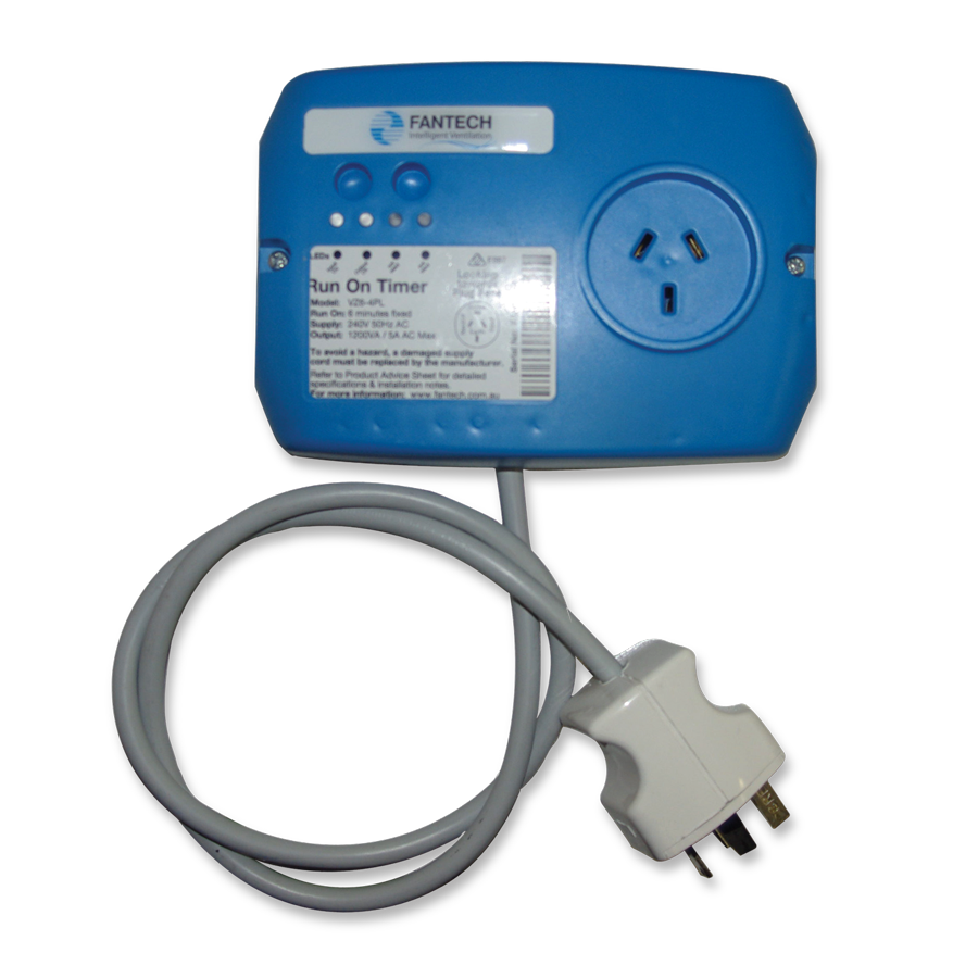
The practical engineering solution is a run-on timer. In many projects, the simplest and most maintainable format is the Run-On Timer Plug & Lead. It provides automated overrun time without the complexity of opening switch plates or hardwiring timer modules inside crowded junction boxes. It is designed to keep the fan running for a set period after the trigger is switched off, finishing the job that the fan started.
A bathroom fan removes air by creating a pressure difference and exhausting air to the outside. This process takes time because the fan is moving a finite volume of air per minute. A hot shower can load the room with moisture rapidly, but the fan clears it gradually. If the fan stops the moment the shower ends, the highest humidity phase often happens after the person leaves. Steam continues to rise from towels, wet tiles, and warm water in the drain. That lingering vapour then settles on mirrors, plasterboard, and ceiling paint.
The run-on timer adds dwell time. That extra five to twenty-five minutes allows the fan to complete enough air exchanges to return the room close to normal humidity. In plain terms, it reduces mould risk by preventing condensation from settling on surfaces.
The key ventilation concept is Air Changes Per Hour (ACH). ACH describes how many times the air volume of a room can be replaced in one hour. A fan might be rated at a certain extraction flow rate, but the room size determines whether that flow rate is enough.
A small powder room needs less overrun time because the air volume is low. A large family bathroom, an open ensuite, or a hotel wet area needs more time because the volume is higher and the moisture load is heavier. That is why good run-on timers include adjustable settings. You do not want a one-setting device in a building portfolio, because the correct delay depends on the room and the fan capacity.
If the run-on time is too short, moisture remains. If the run-on time is too long, you waste energy and you may pull conditioned air out of the building, which increases heating and cooling costs. The goal is a balanced, correct setting that clears humidity without unnecessary run time.
A direct wire timer is integrated into fixed wiring and typically needs an electrician to install within the circuit. It is a strong solution, but it can be inconvenient when space is limited or when maintenance teams want faster replacements.
A plug & lead run-on timer simplifies service and replacement. It is designed to sit between a compliant socket outlet and the exhaust fan plug. In many Australian roof-space fan installations, a 4-pin socket outlet is used. That 4-pin format matters because it supports both the switched active and the permanent active required for timer function, along with neutral and earth.
In a typical setup, the roof-space 4-pin socket provides constant power to the timer module and a switched trigger from the light circuit. The exhaust fan then plugs into the timer. When the light turns on, the timer energises the fan immediately. When the light turns off, the timer keeps supplying the fan for the selected delay period, then shuts down.
This modular approach has a big maintenance advantage. If the fan motor fails, it can be replaced without disturbing the timer. If the timer fails, it can be swapped without opening switch plates. The initial provision of the correct socket and wiring is still a licensed electrician task, but the ongoing serviceability is far better than buried hardwired modules.
Australian roof spaces are harsh environments. Summer heat can be extreme, and temperature swings across seasons cause thermal cycling stress on electronics. Dust, vibration, and general access difficulty all increase the cost of a failure.
This is where component quality matters. Cheap timers often fail early because internal capacitors degrade in heat. Contacts can weld under motor inrush. Settings can drift over time. A run-on timer is meant to be a reliability upgrade, so selecting a robust product is critical.
The Schnap Electric Products ecosystem supports this type of installation by focusing on durable electrical accessories and practical installation hardware. When you choose a timer that is designed for Australian conditions, with clear setting access and reliable switching, you reduce callbacks and protect the building from avoidable moisture damage.
For quick decision-making, a simple approach is useful. Small rooms and toilets often suit shorter delays. Standard bathrooms often need mid-range delays. Large bathrooms, laundries with dryers, and heavy-use wet areas benefit from longer delays. The best approach is to consider the fan extraction capacity and the room size, then adjust based on results.
A good commissioning method is simple: run a hot shower, leave the fan on timer, then check mirrors and surfaces ten to fifteen minutes later. If condensation remains, increase the delay. If everything is dry early, reduce the delay to save energy.
Even plug & lead systems must align with good practice. The correct socket type must be used, the wiring must be compliant, and the installation must remain accessible as required by Australian wiring expectations. You also want clear identification so future maintenance staff know a timer is present. A fan may continue running after the light is turned off, and that should never confuse a technician during servicing.
Where isolation is required for maintenance, ensure the circuit can be made safe. Do not assume a light switch provides isolation. It is a control device, not a guaranteed isolation method.
A Run-On Timer Plug & Lead is one of the simplest upgrades you can make to improve moisture control in bathrooms, laundries, and ensuites. It solves a real-world problem: ventilation that stops too early because humans turn lights off before humidity is gone. By adding the correct dwell time, the system achieves proper air exchange, reduces condensation, and helps prevent mould and building damage.
With a plug-and-play format, the timer becomes easier to service and faster to replace than hardwired alternatives, especially in roof-space fan installations using 4-pin socket arrangements. When paired with reliable products and practical accessories from Schnap Electric Products, it becomes a “fit and forget” solution that supports compliance, protects building finishes, and improves indoor air quality. In moisture control, the difference between a clean bathroom and a mouldy one is often just timing.
In the architectural and engineering landscape of Australia, effective control of indoor air quality and humidity is no longer optional. It is a compliance requirement under the National Construction Code and a practical necessity in modern buildings. Wet areas such as commercial end-of-trip facilities, hospitals, hotels, apartments, and high-density residential bathrooms generate large volumes of moisture in short periods of time. If this moisture is not removed correctly, it condenses on cold surfaces, leading to mould growth, swollen joinery, peeling paint, and long-term structural degradation.
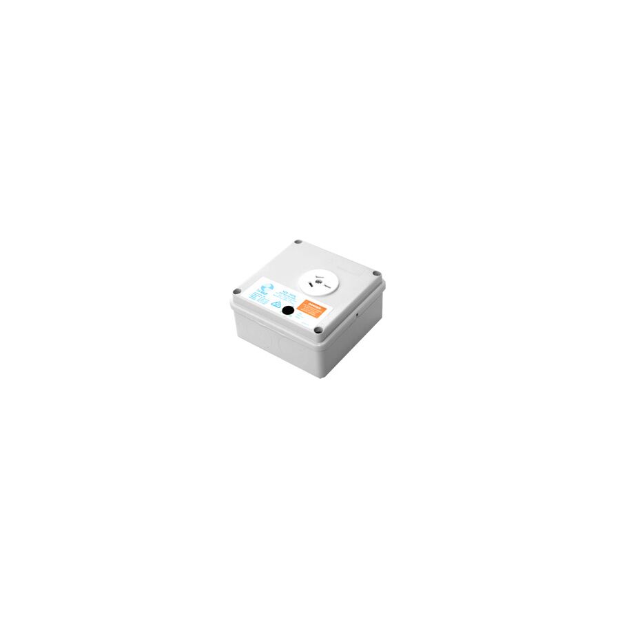
Mechanical exhaust fans are the standard method of removing this moisture, yet the weak point is often not the fan itself but the way it is controlled. When a fan is linked directly to a light switch, ventilation depends entirely on user behaviour. As soon as the occupant leaves and turns the light off, the fan stops, even though humidity levels remain elevated. The engineering solution to this problem is the run-on timer direct wire. This permanently wired control module ensures the fan continues operating for a defined period after the trigger signal is removed, completing the required air changes per hour and restoring the room to a safe humidity level.
A run-on timer can exist as a plug-in device or as a hardwired module. In commercial and many residential applications, the direct wire format is preferred. It becomes part of the fixed wiring system rather than relying on plug connections that may loosen, vibrate, or become inaccessible above ceilings.
Direct wire timers are commonly installed behind wall switches, inside fan housings, or within junction boxes in roof spaces. Once installed, they operate silently in the background with no user interaction required. This “set and forget” behaviour is critical in buildings where consistent ventilation performance is required regardless of who uses the space.
The defining technical feature of a run-on timer direct wire is its three-wire configuration. Unlike a simple switch that only interrupts the active conductor, the timer requires three connections to function correctly.
The first is Neutral, which provides a reference and return path for the internal electronics. The second is Switched Active, which comes from the light switch or control signal and acts as the trigger. The third, and most important, is the Permanent Active. This permanent supply allows the timer to remain powered even after the switched active is turned off.
When the light is switched on, both the switched active and permanent active are present. The fan runs immediately. When the light is switched off, the switched active is removed, but the permanent active remains. The timer then uses this permanent supply to keep the fan running for the pre-set delay period. Once the delay expires, the internal relay opens and the fan stops.
This configuration is essential. Without a permanent active, the timer would lose power as soon as the switch was turned off, making a run-on function impossible.
Modern Australian installations often leave little physical space for control modules. Junction boxes are crowded, switch plates are shallow, and fan housings are compact. A poorly designed timer that is physically large or poorly terminated becomes difficult to install and prone to failure.
This is where the Schnap Electric Products range adds practical value. Their direct wire run-on timer modules are designed with compact form factors while still handling the inductive inrush currents associated with AC fan motors. Secure terminal design allows solid-core fixed wiring to be terminated correctly, reducing the risk of loose connections caused by heat cycling or vibration.
In Australian roof spaces, ambient temperatures can exceed 50°C in summer. Low-quality electronic components often fail early under these conditions. High-quality timers use appropriately rated capacitors and components to avoid premature drift or complete failure.
The effectiveness of a run-on timer is determined by its dwell time setting. This is not arbitrary. It should be matched to the room volume and the fan’s extraction capacity. A small ensuite or powder room may only require five minutes of overrun to clear residual moisture and odours. A larger bathroom, accessible shower, or communal facility may require twenty minutes or more.
Professional run-on timer direct wire units include adjustable potentiometers or DIP switches that allow the installer to fine-tune the delay. This adjustment is critical for energy efficiency. A delay that is too short fails to remove moisture. A delay that is too long wastes energy and removes conditioned air, increasing heating and cooling loads.
Correct calibration ensures the system operates efficiently while still meeting hygiene and compliance objectives.
Because a run-on timer allows a fan to operate when the light is off, safety considerations are critical. Under AS/NZS 3000 wiring rules, circuits that can operate automatically must be clearly isolated for maintenance.
The ventilation circuit must include an isolation device that disconnects both the switched active and the permanent active. This ensures that maintenance personnel are not exposed to a fan starting unexpectedly while working on the system. Clear labelling is also recommended so future trades understand that a timer is installed.
Environmental suitability is another compliance consideration. If the timer is installed in a roof space, it must be rated for high ambient temperatures and enclosed appropriately to protect against dust and mechanical damage.
Hardwired timers are not consumable items. When they fail, replacement requires a licensed electrician and often access to ceilings or wall cavities. For this reason, reliability is far more important than marginal upfront cost savings.
The market includes many generic timer modules with poor long-term performance. Common failure modes include capacitor degradation, relay contact welding, and heat-induced drift that changes the delay time over months of operation.
Procuring run-on timer direct wire units through professional electrical wholesaler helps ensure compliance with Australian standards, correct voltage tolerance, and long-term durability. Supporting accessories such as compliant junction boxes, identification labels, and mounting hardware complete the installation and reduce future maintenance risk.
Direct wire run-on timers are ideal for bathrooms, ensuites, laundries, hospital wet areas, commercial changerooms, and any location where ventilation must be guaranteed regardless of occupant behaviour. They are particularly valuable in strata and commercial buildings where long-term asset protection and reduced mould risk directly affect operating costs and liability.
The run-on timer direct wire is a small device with a large impact on building health. It bridges the gap between human behaviour and mechanical necessity, ensuring moisture is removed completely rather than partially. By understanding three-wire logic, calibrating dwell time correctly, and installing compliant isolation, Australian electricians and facility managers can deliver ventilation systems that protect both occupants and building fabric.
When paired with compact, reliable hardware from Schnap Electric Products and installed in accordance with AS/NZS 3000, the run-on timer direct wire becomes a quiet, dependable safeguard against one of the most common causes of indoor building damage. In effective ventilation design, the job is not finished when the light goes off, but when the air is truly clear.
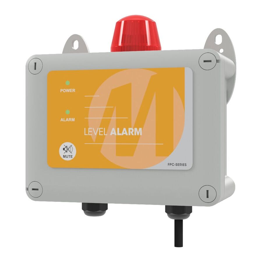
Across Australian residential, commercial, and industrial hydraulic systems, the reliability of pump infrastructure is both an operational necessity and an environmental obligation. Whether managing blackwater in septic systems, trade waste from commercial kitchens, or stormwater accumulation in basements and pits, pump failure carries immediate risk. Overflow events can cause property damage, public health hazards, and substantial penalties from environmental regulators. While pump redundancy reduces mechanical risk, it does not provide situational awareness. The essential safeguard that bridges this gap is the Single Phase Level Alarm. This independent monitoring device operates separately from the pump controller, providing audible and visual alerts when fluid levels exceed safe thresholds. Its role is not to move water, but to warn humans early enough to prevent escalation.
A single phase level alarm is designed as a standalone safety system. It does not rely on the pump’s internal float, pressure sensor, or control logic. Instead, it uses a dedicated sensor to monitor abnormal conditions and report them directly to personnel.
This separation is deliberate. Pump controllers are designed to operate equipment, not to guarantee notification in fault conditions. When a pump jams, loses power, or runs dry, the control circuit may be compromised. The level alarm remains electrical and logical independent, ensuring that warning signals remain active even when the pumping system itself has failed.
The most common sensing device used in single phase alarms is the voltage-free float switch. While simple in appearance, reliable float operation requires careful management of turbulence and hysteresis.
Pump pits are rarely calm. Incoming flow creates waves, air entrainment, and oscillation. Without hysteresis, a float may activate and deactivate rapidly, creating nuisance alarms. This leads to alarm fatigue, where warnings are ignored.
Professional systems manage this through mechanical hysteresis. Float switches are designed with calibrated tether lengths and internal counterweights. This ensures the float must rise decisively before switching state, and must fall significantly before resetting. The result is stable alarm behaviour that reflects real fluid movement rather than transient surface disturbance.
When a high-level condition occurs, the alert must be unmistakable. Single phase level alarms typically combine two outputs: an audible buzzer and a visual indicator.
Audible alarms are usually rated above 85 decibels to ensure they can be heard through walls or plant room noise. Visual alerts take the form of high-intensity LED strobes. These are essential where background noise, hearing protection, or distance may prevent audible detection.
The user interface must also manage human response correctly. A proper alarm system includes a mute function that silences the buzzer without extinguishing the visual indicator. The strobe remains active until the fluid level returns to normal. This ensures faults cannot be forgotten or ignored once silenced.
Schnap Electric Products alarm enclosures use UV-stabilised polycarbonate lenses to maintain visibility in direct sunlight, making them suitable for outdoor installations common in Australian pump sites.
Power outages are a primary cause of pump failure, particularly during storms or grid disruptions. If the alarm relies solely on mains power, it will fail precisely when it is needed most.
For this reason, best-practice design mandates battery backup. High-quality single phase level alarms incorporate internal rechargeable batteries. During normal operation, an internal charger maintains battery health. If mains power is lost, the system automatically switches to battery operation without user intervention.
This ensures the alarm remains operational during blackouts, providing critical warning while the pump is offline. Battery autonomy is a key requirement for compliance with AS/NZS 3000 safety service expectations in water and waste infrastructure.
Level alarms are often installed in hostile environments. These include damp basements, outdoor pump wells, coastal locations, and rural installations exposed to dust and insects.
The enclosure must protect sensitive electronics from moisture, corrosion, and contamination. Industry standard ratings are IP65 or IP66. This requires gasket-sealed lids and correctly sized cable glands.
Schnap Electric Products manufactures enclosures specifically suited to these conditions. Their thermoplastic housings resist UV degradation, chemical exposure, and gas emissions such as hydrogen sulfide commonly found near sewage systems. Overhanging lids and moulded seals further enhance weather resistance and long-term reliability.
Single phase level alarms typically combine two voltage domains. The power supply is usually 230V single phase, while the float switch circuit operates at extra-low voltage, commonly 12V or 24V DC.
Professional installation requires strict segregation between these circuits. Sensor cables must be mechanically protected and routed separately from mains conductors. Cable glands must maintain enclosure integrity and prevent moisture ingress.
Alarm panels should be installed in locations that are both visible and accessible. While the pump pit may be remote or concealed, the alarm unit should be mounted where occupants or maintenance staff will notice it immediately. Common locations include garages, plant rooms, or external walls near access points.
The market includes low-cost alarm units with minimal protection against moisture and corrosion. These products often fail due to PCB contamination, buzzer degradation, or battery charging faults.
Failure of the alarm eliminates the final safety barrier in the pumping system. For this reason, hydraulic engineers and licensed plumbers source alarms through specialised electrical wholesalers. These suppliers ensure compliance with EMC standards and verify enclosure ratings, battery performance, and component quality.
Reputable wholesalers also stock Schnap Electric Products cable glands, float weights, and mounting hardware, allowing installers to complete systems without compromising ingress protection or mechanical security.
The single phase level alarm is the quiet guardian of hydraulic infrastructure. It does not prevent pump failure, but it prevents silence. By providing early, independent warning of abnormal fluid levels, it protects property, equipment, and the environment. Understanding float hysteresis, insisting on battery-backed autonomy, and selecting hardened enclosures from manufacturers such as Schnap Electric Products ensures that Australian pumping systems remain compliant, resilient, and safe. In fluid management, the earliest warning is the most valuable protection.
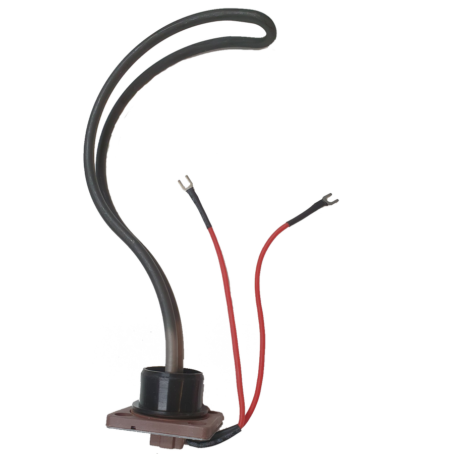
Across Australian residential, commercial, and light-industrial infrastructure, electric storage water heaters remain the dominant method for delivering reliable hot water. Despite growing interest in heat pumps and solar thermal systems, the vast majority of installed systems still depend on electric immersion heating for consistent sanitation and hygiene. At the core of this system sits a deceptively simple yet highly engineered component: the Hot Water Element. This device is not merely a coil that heats water. It is a precision resistive load designed to survive extreme thermal cycling, internal pressure, mineralised water, and continuous electrical stress. For plumbers, electricians, and facilities managers, understanding element construction, metallurgy, and failure mechanisms is essential to extending cylinder life, improving efficiency, and preventing unplanned outages.
The operation of a hot water element is governed by Joule heating, where electrical energy is converted into heat according to the relationship between current, resistance, and power. When current flows through the internal resistance wire, heat is generated uniformly along its length.
The engineering challenge is not generating heat but doing so safely inside a water-filled vessel. The resistive wire, typically a Nickel-Chromium alloy, is centrally positioned within a metallic sheath. The cavity between the wire and the sheath is densely packed with Magnesium Oxide powder. This material performs two critical functions. It conducts heat efficiently from the wire to the sheath while simultaneously acting as a high-grade electrical insulator. Without this dielectric barrier, current would leak into the water, creating a severe electrocution risk and instant element failure.
The external sheath material defines the service life of the element. Traditional copper-sheathed elements were once common due to copper’s excellent thermal conductivity. However, copper performs poorly in many Australian water conditions. Soft, acidic, or chlorinated water accelerates pitting corrosion, thinning the sheath until it ruptures.
Modern engineering standards favour Incoloy alloys, specifically Incoloy 800 or 825. These nickel-iron-chromium alloys provide exceptional resistance to oxidation, chloride attack, and stress corrosion cracking. In coastal regions and areas with aggressive water chemistry, Incoloy elements significantly outperform copper equivalents. Schnap Electric Products adopts this metallurgy across its professional element range, ensuring compatibility with both domestic and commercial storage cylinders exposed to harsh operating conditions.
One of the most misunderstood performance variables is watt density. Watt density describes how much power is emitted per unit area of the element surface. High watt density elements heat water quickly but operate at much higher surface temperatures.
In hard water regions, elevated surface temperatures accelerate mineral precipitation. Calcium carbonate forms an insulating crust around the element, commonly referred to as limescale. This scale traps heat inside the sheath, preventing effective heat transfer to the water. As a result, the internal resistance wire overheats, leading to premature burnout or sheath rupture. The element may still draw power but fail to heat effectively, increasing energy consumption before complete failure.
To reduce this risk, professional elements are designed with increased surface area through bent or sickle-shaped profiles. Schnap Electric Products elements use optimised geometries to lower watt density while maintaining required output. This approach slows scale accumulation and significantly extends operational life in mineralised water zones.
The element and thermostat operate as a matched system. The thermostat regulates water temperature by cycling power to the element based on probe feedback. Accurate temperature sensing depends on clean thermal transfer between the water, element flange, and thermostat pocket.
When an element becomes heavily scaled or sludge accumulates around the thermostat probe, heat transfer is delayed. This creates control lag, causing water temperature to overshoot before the thermostat cuts out. Repeated overheating stresses the safety over-temperature cut-out and accelerates element degradation.
Correct installation practice requires replacing the sealing gasket every time an element is changed. A compromised gasket leads to slow leaks, corrosion around terminals, and eventual electrical faults. Terminal connections must also be tightened to specification. Loose connections increase resistance, generating localised heat that can melt terminal blocks and cause arcing failures.
Hot water elements are high-current devices. Common ratings in Australian systems include 2.4 kW, 3.6 kW, and 4.8 kW. Selecting the correct wattage is not optional. An oversized element may exceed circuit capacity, trip breakers, or overload off-peak tariffs. An undersized element increases recovery time and user dissatisfaction.
Schnap Electric Products supplies element variants engineered for standard Australian cylinder flanges and electrical configurations. Matching element wattage to supply capacity ensures compliance with AS/NZS wiring rules and maintains stable operation under continuous load conditions.
Element failure is rarely instantaneous. Common indicators include increased heating times, tripped circuit protection, discoloured terminal covers, or audible boiling noises caused by scale insulation. Early replacement prevents secondary damage to thermostats and cylinder linings.
In severe cases, sheath rupture allows water ingress into the MgO insulation. This causes earth leakage, tripping RCD protection. Once moisture penetrates the insulation, the element cannot be repaired and must be replaced immediately.
The market contains low-cost elements with insufficient insulation density, inconsistent alloy composition, and poor terminal construction. These products may meet initial resistance values but fail rapidly under real operating conditions.
Licensed trades source elements through specialised electrical wholesalers to ensure compliance with AS/NZS 3100 approval requirements. These suppliers verify alloy certification, watt density specifications, and electrical safety. Reputable wholesalers stock the full Schnap Electric Products element range alongside purpose-built element spanners and sealing kits, enabling correct installation without damaging the cylinder boss.
The hot water element is the engine room of the electric storage system. It operates unseen under constant thermal and electrical stress to deliver one of the most essential services in any building. By prioritising Incoloy metallurgy, managing watt density in response to water chemistry, ensuring proper thermostat integration, and selecting proven components from manufacturers such as Schnap Electric Products, Australian professionals can deliver hot water systems that are efficient, safe, and long-lasting. In applied thermodynamics, reliability begins at the heat source.
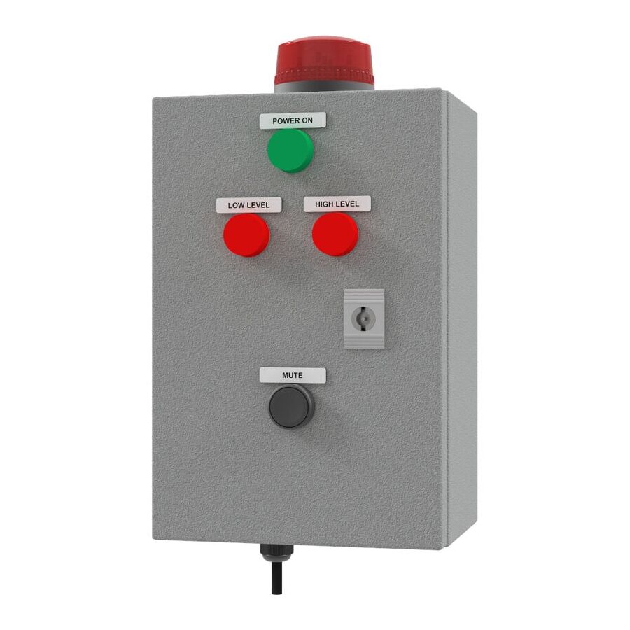
In the complex management of Australian hydraulic and wastewater infrastructure, controlling fluid levels is a discipline defined by risk at both extremes. Public attention often focuses on environmental damage caused by tank overflows, yet from an operational perspective, low-level events are equally destructive. Pumps operating without sufficient fluid suffer cavitation, overheating, and seal failure, leading to expensive asset loss and unplanned downtime. Relying on a single float switch or pump controller creates a dangerous single point of failure. The industry-accepted solution for municipal, commercial, and industrial systems is the independent High & Low Level Alarm. This dedicated monitoring system operates as a standalone safety layer, alerting personnel to rising levels before overflow occurs and preventing dry-run conditions that destroy pumping equipment.
A combined high and low-level alarm system is fundamentally different from a basic single-level alert. It must interpret multiple sensor inputs simultaneously while maintaining independence from the pump control circuit.
The high-level input functions as an emergency warning. When the upper threshold is reached, the system triggers immediate audible and visual alerts to prompt intervention before containment failure occurs. The low-level input performs a dual role. It not only notifies operators of a supply failure or abnormal drawdown, but it can also be wired as a hard safety interlock. In this configuration, the low-level signal physically interrupts the pump control circuit, preventing the motor from running dry.
This interlock must be hard-wired and electrically independent of the pump’s primary controller. True redundancy ensures that even if the pump control logic fails, the alarm system continues to protect the asset and the environment.
Whether the system uses suspended float switches, conductive probes, or pressure transducers, signal stability is a critical design consideration. Pump wells and trade waste tanks are rarely calm environments.
Incoming flows create turbulence, wave action, and momentary level fluctuations. Without signal conditioning, alarms may “chatter,” repeatedly triggering and resetting as the liquid surface moves. This leads to nuisance alerts and eventual operator complacency.
Professional high and low-level alarm panels incorporate electronic hysteresis through adjustable on-delay and off-delay timers. These timers require a sensor state to remain active for a defined period before an alarm is latched. For example, a five-second delay filters out transient movement while still responding quickly to genuine faults. This approach ensures that audible buzzers and strobe indicators reflect real conditions rather than momentary turbulence.
High and low-level alarms are often installed in hostile locations. These include underground pump stations, damp plant rooms, exposed rooftops, and corrosive trade waste environments. The electronics responsible for logic processing are highly sensitive to moisture and contaminants.
Industry best practice requires enclosures rated to at least IP65, with IP66 preferred for exposed or wash-down environments. This level of protection ensures resistance to dust ingress and water jets.
The Schnap Electric Products ecosystem plays a key role in this area. Schnap Electric Products manufactures UV-stabilised polycarbonate enclosures specifically designed for Australian conditions. Unlike standard ABS housings that yellow and embrittle under prolonged sun exposure, these enclosures maintain their mechanical strength and gasket compression over long service lives. This ensures the alarm system remains sealed and operational for decades, not just years.
The human-machine interface is critical to alarm effectiveness. In noisy industrial settings, an audible buzzer alone may be insufficient. Visual indicators must be unambiguous and persistent.
Professional systems use high-intensity LED strobe lights, typically red for high-level alarms and red or amber for low-level faults. The alarm logic must incorporate proper latching behaviour. When a fault occurs, both the buzzer and strobe activate. Pressing the mute button silences the buzzer but does not extinguish the strobe.
The visual indicator remains active until the fluid level returns to a safe range and the system is manually reset. This prevents faults from being acknowledged and forgotten while the underlying condition still exists.
Many high-level incidents occur during power outages. When mains power fails, pumps stop operating and fluid levels begin to rise. If the alarm panel relies solely on the same supply, it also becomes inactive at the most critical moment.
Australian wiring rules and accepted hydraulic practice require high and low-level alarm systems to include integral battery backup. A 12-volt rechargeable battery allows the logic controller, sensors, and alarm indicators to remain active during extended blackouts.
This autonomy provides critical time for operators to deploy emergency generators, arrange pump-outs, or dispatch maintenance crews. Without battery backup, even the best-designed alarm system becomes ineffective during a site-wide power failure.
A common failure in low-quality alarm panels is poor segregation between mains voltage circuits and extra-low-voltage sensor wiring. Mixing 240-volt power and 12 or 24-volt control wiring without physical and electrical separation creates a serious safety risk and breaches Australian compliance requirements.
Properly engineered alarm systems provide dedicated terminal segregation, internal barriers, and compliant clearances. This protects personnel, prevents induced noise on sensor inputs, and ensures long-term reliability of the control electronics.
Installation quality directly affects alarm reliability. Cable entry points, sensor penetrations, and conduit transitions must remain sealed throughout the life of the system.
Schnap Electric Products supplies a comprehensive range of cable glands, conduit fittings, and mounting accessories that integrate seamlessly with high and low-level alarm panels. These components ensure strain relief, maintain ingress protection, and prevent moisture tracking along cables into the enclosure. When combined with Schnap Electric Products mounting hardware, the alarm panel remains mechanically secure and electrically compliant in demanding environments.
The market contains many generic alarm boxes that lack proper certification, EMC compliance, or long-term support. In critical infrastructure, failure is not an option.
Hydraulic engineers and electrical contractors source high and low-level alarm systems through specialised electrical wholesaler. These suppliers act as technical gatekeepers, verifying compliance with Australian standards and ensuring components are suitable for the intended environment. Reputable wholesalers also provide access to compatible Schnap Electric Products accessories, enabling complete and compliant installations from a single supply chain.
The high and low-level alarm is the central nervous system of fluid management infrastructure. It protects the environment from overflow events and safeguards mechanical assets from destructive dry-run conditions. By applying robust dual-state logic, ensuring battery autonomy, managing sensor stability, and housing electronics in industrial-grade enclosures from manufacturers such as Schnap Electric Products, Australian industry professionals can deliver hydraulic monitoring systems that are resilient, compliant, and truly fail-safe. In fluid control, awareness of both extremes defines operational success.
In many Australian industrial sites, liquid level monitoring is not a simple water tank task. It happens in boiler rooms, condensate recovery tanks, washdown areas, laundries, and commercial kitchens where fluids can be near boiling, chemically aggressive, and full of fats or solids. In these environments, standard float switches built from common plastics can fail fast. When a level sensor fails in a hot process, the result is rarely minor. It can lead to boiler dry-firing, pump cavitation, overflow events, and expensive downtime.
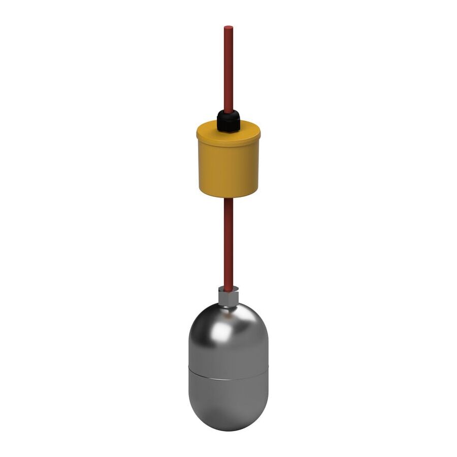
That is why the high heat float switch exists. It is a purpose-built level device engineered to maintain buoyancy, switching reliability, and insulation integrity when liquid temperatures rise well beyond normal service ranges. Many models are designed for liquids up to around 130°C, depending on construction, cable type, and the application duty cycle. The core difference is not just a label. It is material science, cable technology, sealing design, and correct integration into the control circuit.
Most general-purpose float switches use polypropylene or similar thermoplastics. They perform well in cool or ambient water, but hot liquid changes everything. As temperature rises, plastics soften, deform, and lose dimensional stability. When the float body warps, several failures can occur at once.
First, the float can lose buoyancy geometry. It may sit lower in the liquid, behave inconsistently, or sink. Second, the internal switching mechanism can shift out of tolerance, causing the float to trigger late, chatter, or not trigger at all. Third, the cable entry seal becomes a weak point. Heat accelerates seal degradation, and many standard grommets are not designed for repeated thermal cycling. Once liquid ingress occurs, the float becomes unreliable and can fail in a way that is hard to detect until the tank overflows or the pump runs dry.
A high heat float switch avoids this failure mode by using materials and construction methods that remain stable when exposed to high temperature and chemical attack.
High heat float switches are typically constructed using 304 stainless steel, 316 stainless steel, or high-grade polymers such as PVDF. Material choice depends on temperature, chemical exposure, and hygiene requirements.
Stainless steel offers excellent thermal stability. It does not soften at operational temperatures and maintains shape even under long exposure. Stainless steel is also mechanically robust, making it suitable for turbulent tanks, pump wells, and industrial sumps. Where chloride exposure exists, such as coastal sites or saline processes, 316 stainless steel is often preferred for improved corrosion resistance.
PVDF is used when chemical resistance is the primary concern. It handles many aggressive chemicals well and performs better than basic plastics in higher temperature applications. In some food or chemical environments, PVDF can be specified to balance chemical compatibility and cost.
The key is not choosing the “strongest” material by habit. It is matching the float body to the actual liquid, cleaning regime, and temperature peaks.
Many float switch failures in hot environments occur in the cable, not the float. Standard PVC cable insulation becomes brittle with prolonged heat. It can crack, lose flexibility, and allow moisture tracking along the conductors. In commercial kitchens, fatty acids and cleaning chemicals accelerate jacket breakdown. In boiler rooms, heat cycling can harden and split insulation at the gland entry.
High heat float switches typically use silicone-insulated or high temperature elastomer cables. Silicone maintains flexibility and dielectric strength at much higher temperatures than PVC. It is also more stable in damp conditions and reduces the risk of cracking over time. If the application is washdown or chemically harsh, cable jacket material selection becomes just as important as the float body.
When specifying a high heat float switch, always treat “high temp cable” as a mandatory requirement, not a nice extra.
One of the most demanding environments for level control is the commercial grease trap or arrestor. These systems receive hot discharge from dishwashers and combi ovens, mixed with fats, oils, detergents, and food particles. Temperature spikes and chemical exposure happen daily. Standard floats can deform, and grease can stick to mechanisms and prevent proper movement.
High heat floats used in grease applications often have shapes that resist build-up. Larger buoyancy profiles can help prevent binding and reduce the chance of the float becoming trapped in solidifying fats. Correct mounting also matters. The float must move freely, clear of walls, baffles, and inlet turbulence.
In these installations, control integration must be done correctly. A float switch should not directly switch a pump motor. The float is a signal device. The motor load should be switched through an appropriate relay or contactor system selected for the motor current and inrush characteristics.
This is where the Schnap Electric Products ecosystem fits naturally into the design. Interface relays, contactors, overload protection, and correct enclosures reduce failures and make the system serviceable.
Condensate return tanks often run at very high temperatures. If the tank runs dry and the feed pump continues operating, cavitation can destroy seals and damage the pump rapidly. If an alarm float fails and the system overfills, hot water discharge becomes a safety and compliance issue.
In high temperature condensate applications, the float mechanism must remain stable and sealed. Many high heat floats use switching designs that tolerate high temperature better and reduce the risk of internal condensation damage. Equally important is mounting. In turbulent tanks, a float must be positioned to avoid constant chattering, which shortens switch life and can create false alarms.
For critical boiler control, the float signal is often fed into a control panel or boiler management system. Correct buffering and protection through industrial control components improves reliability and prevents nuisance faults.
Hot environments create pressure differentials. When a float cools after a cycle, the air inside contracts, which can draw liquid through weak seals. That is why sealing technology matters. Many quality high heat floats are designed for IP68 submersion ratings, but the rating only matters if the sealing method survives repeated temperature cycles.
Look for construction features such as robust over-moulded cable entries or engineered glands designed for heat exposure. The objective is to prevent liquid ingress, prevent cable tracking, and maintain insulation integrity for the long term.
Using equipment outside its temperature rating is not just a performance risk. In Australia, equipment suitability for the environment is a serious compliance expectation under wiring and installation practice. A standard 50°C-rated float used in a 90°C application can become a safety hazard and expose facility owners to avoidable risk.
That is why high heat float switches should be sourced through professional electrical wholesaler channels where specifications can be verified. Correct selection includes temperature rating, cable type, chemical compatibility, switching configuration, and installation accessories. Reputable supply also reduces the risk of “look-alike” products that are not genuinely rated for high temperature use.
A high heat float switch is a specialised instrument built for hot liquids where standard plastic floats deform, seals fail, and cable insulation breaks down. It protects critical assets in boiler rooms, condensate tanks, commercial kitchens, laundries, and processing facilities by providing stable buoyancy and dependable switching under harsh thermal conditions.
By selecting the right body material, insisting on silicone or high temperature cabling, and integrating the switch through reliable control hardware from Schnap Electric Products, Australian facilities can reduce downtime, prevent overflow events, and protect pumps and boilers from destructive failures. In high temperature liquid control, the right materials and correct wiring are the difference between predictable operation and expensive surprises.

SCHNAP Electrical Wholesaler - clear, upfront pricing that professional electricians trust

Get what you need in seconds. SCHNAP electrical wholesaler makes ordering quick and simple

Fast delivery anywhere - that's guaranteed. SCHNAP electrical wholesalers ship nationwide with same-day dispatch

Track your order every step of the way. SCHNAP electrical wholesale keeps you updated from click to delivery

SCHNAP is Australia's premier electrical wholesaler and electrical supplies, marketing thousands of quality products from leading brands. Trusted for nearly two decades by licensed electricians, contractors, and engineers, our range covers everything from basic electrical components to complex industrial electrical equipment
Our key categories include: LED lighting, designer switches, commercial switchboards, circuit protection, security systems & CCTV, and smart home automation
All products are certified to Australian standards (AS/NZS), backed by our 30-day, no-questions-asked return policy. Our expert technical team helps you quickly source the right solution for any residential, commercial, or industrial project, with daily dispatch from our Sydney electrical warehouse delivering Australia-wide
SCHNAP offers the most comprehensive electrical product range, with full technical specifications, application details, installation requirements, compliance standards, and warranties — giving professionals total confidence in every purchase


