




Kingsgrove Branch:

Across the vast and climatically diverse Australian continent, accurate water level monitoring underpins essential services and industrial productivity. From agricultural bore fields in remote inland regions to stormwater detention systems and municipal sewage lift stations in major cities, the ability to continuously measure liquid levels is central to operational safety, energy efficiency, and regulatory compliance. While traditional float switches remain suitable for basic start-stop control, they provide no insight into trends, inflow rates, or available storage. Modern telemetry, SCADA, and Variable Speed Drive (VSD) systems require continuous, linear data. The instrument that fulfils this role reliably in harsh environments is the hydrostatic level transducer.
Unlike ultrasonic or radar sensors that operate above the liquid surface and are affected by foam, vapour, condensation, or narrow shafts, the hydrostatic transducer is fully submersible. Installed at the bottom of the vessel, it measures the pressure exerted by the liquid column above and converts that force into an electrical signal proportional to depth. This simplicity, combined with robust materials and proven physics, makes it the preferred standard for Australian water and wastewater applications.
The operation of a hydrostatic level transducer is based on a fundamental physical relationship: the pressure exerted by a fluid increases linearly with depth. This relationship is described by the equation P = ρgh, where pressure depends on fluid density, gravitational acceleration, and liquid height.
Inside the sensor body, typically machined from stainless steel, a thin diaphragm is exposed to the surrounding liquid. Behind this diaphragm sits a piezoresistive silicon element arranged in a Wheatstone bridge configuration. As pressure increases, the diaphragm deflects microscopically. This deformation alters the resistance of the silicon strain gauges, producing a proportional electrical change. Internal electronics amplify and linearise this signal into a standard industrial output.
Because water has a stable specific gravity close to 1.0, the pressure measurement translates directly into depth with excellent repeatability. Approximately 10 metres of water column equates to 100 kilopascals of pressure. This predictable relationship allows hydrostatic transducers to achieve high accuracy without complex calibration routines.
One of the most critical design features of a professional hydrostatic level transducer is atmospheric pressure compensation. Pressure at the sensor diaphragm is influenced not only by liquid depth but also by barometric pressure acting on the liquid surface. Weather systems passing over a site can change atmospheric pressure by several kilopascals, introducing level errors of hundreds of millimetres if not compensated.
To eliminate this variable, most industrial hydrostatic transducers use a vented cable. A micro-bore capillary tube runs alongside the signal conductors from the sensor body to the termination point. This tube exposes the rear side of the diaphragm to ambient air pressure, allowing the sensor to measure gauge pressure rather than absolute pressure.
Correct handling of the vent tube is essential. Moisture ingress into the vent line will condense and damage the sensing element. For this reason, the cable termination must include a desiccant breather or atmospheric filter. This component equalises pressure while preventing humidity and dust from entering the vent path. Improper termination is one of the most common causes of long-term transducer failure.
In Australian industrial environments, sensors are often located tens or hundreds of metres from control panels. Voltage-based signals degrade over long distances due to resistance and electromagnetic interference. For this reason, hydrostatic level transducers almost universally employ the 4–20mA current loop standard.
In this configuration, the sensor modulates current rather than voltage. Four milliamps represent the zero or empty condition, while twenty milliamps represent the full-scale measurement. This “live zero” allows immediate fault detection. If the cable is damaged or power is lost, the signal drops to zero milliamps, which is clearly distinguishable from a valid empty reading.
Current loops are inherently immune to voltage drop and electrical noise, making them ideal for pump stations, bore fields, and treatment plants where motors and switching equipment generate significant interference. The result is stable, accurate data delivery to PLCs, remote telemetry units, and SCADA systems.
While the transducer itself is robust, the signal path must be protected. Submersible sensors installed in exposed locations are vulnerable to lightning-induced surges and ground potential rise, particularly in rural installations and elevated tanks.
This is where the Schnap Electric Products ecosystem becomes essential. Signal-rated surge diverters mounted on DIN rail protect the 4–20mA loop from transient overvoltage. Regulated 24V DC power supplies ensure stable excitation voltage, preventing signal drift and improving long-term accuracy. Shielded terminal blocks and cable glands preserve signal integrity and maintain ingress protection at the control panel.
For sites requiring local indication, loop-powered digital displays can be integrated without additional power supplies, providing operators with instant visual confirmation of tank or well levels.
Correct installation is as important as sensor selection. In turbulent environments such as sewage lift stations or stormwater pits, direct exposure to inflow can cause fluctuating readings. Rapid changes in pressure from splashing or aeration distort the signal and increase mechanical stress on the cable.
Best practice is to install the transducer inside a stilling tube. This vertical pipe, perforated near the base, allows the liquid level to equalise while isolating the sensor from turbulence. The transducer measures a calm representative column of fluid, resulting in stable and repeatable output.
Mechanical support must also be considered. The sensor cable should never support the full weight of the device. A dedicated cable grip or suspension clamp at the wellhead transfers load to the structure and prevents damage to conductors and vent tubing.
Selecting the correct measurement range is critical. A transducer rated for excessive depth will have poor resolution when used in shallow tanks. Conversely, installing an underspecified sensor in a deep bore risks diaphragm damage or overpressure failure.
Professional procurement ensures the sensor range matches the maximum expected liquid height with suitable margin. Fluid type must also be considered. While clean water applications can use standard stainless steel diaphragms, sewage and aggressive trade waste may require ceramic or flush diaphragm designs to prevent fouling and corrosion.
The hydrostatic level transducer remains the gold standard for continuous liquid level measurement across Australian water, wastewater, and industrial applications. Its reliability is grounded in simple physics, robust construction, and proven signal standards. When combined with correct atmospheric compensation, surge protection, and disciplined installation practices, it delivers precise, long-term data that supports energy-efficient control and predictive maintenance.
By integrating quality infrastructure and protection components from manufacturers such as Schnap Electric Products, engineers and operators can deploy hydrostatic level systems that perform accurately in the harshest environments. In fluid management, pressure does not lie, and the hydrostatic transducer turns that pressure into actionable intelligence.
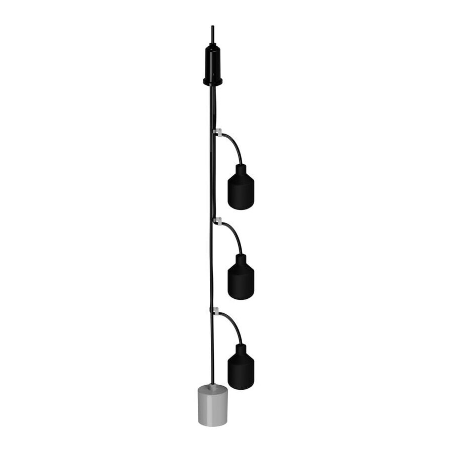
In the hydraulic engineering landscape of Australia, particularly across municipal wastewater and commercial stormwater infrastructure, the reliability of a pump station is rarely limited by the pumps themselves. Modern submersible pumps are mechanically robust, designed to handle abrasive solids and continuous duty cycles. Instead, system failure most commonly originates at the level sensing layer. When level detection becomes unreliable, pumps short cycle, run dry, or fail to start during peak inflow, leading to mechanical damage, flooding, and regulatory exposure.
Historically, float switches were installed individually and suspended loosely from cables at the top of the wet well. While this approach appears simple, it performs poorly in real-world sewage environments. Turbulent inflow, variable pump discharge, and the presence of fibrous debris cause float cables to twist, braid, and eventually entangle. Once this occurs, the logical order of the switching system collapses. The engineering solution adopted by water authorities and experienced contractors is the Multi Level Float Tree. This rigid, vertically structured suspension system establishes fixed geometry for all switching points, preserving operational logic and enabling safe, repeatable maintenance.
A sewage or stormwater wet well is a highly dynamic hydraulic environment. Gravity inflow introduces velocity, turbulence, and rotational currents. Free-hanging float switches respond not only to vertical fluid movement but also to lateral forces. Over time, these forces cause float cables to swing across one another.
When multiple floats operate independently on loose cables, their movement leads to braiding. This condition is amplified by the presence of rags, wipes, and fibrous waste that readily catch on cable insulation. Once cables knot together, floats can no longer move freely. A stop float may remain suspended above its intended level, preventing pump shutdown. The result is pump snoring, cavitation, seal failure, and premature motor burnout.
A multi level float tree eliminates this failure mode by enforcing spatial separation. A rigid central stem, typically manufactured from PVC or stainless steel, provides a fixed vertical axis. Float cables are clipped to this stem at controlled intervals, restricting lateral movement and preventing contact between adjacent floats. Each switch operates within its own defined vertical path, ensuring accurate response to changing liquid levels regardless of turbulence.
The float tree is not simply a mechanical accessory. It is the physical embodiment of the control philosophy programmed into the pump station control panel. In Australian installations, this hierarchy is typically defined by water authority standards and AS/NZS 3000 requirements.
A standard dual-pump lift station will include, from bottom to top, a common stop float, a duty start float, a standby or assist start float, and a high-level alarm float. The vertical spacing between these points is critical. The distance between stop and duty start determines pump cycling frequency. Excessively narrow spacing leads to short cycling, increased electrical wear, and higher energy consumption. Excessive spacing increases wet well volume and may cause odour or sedimentation issues.
The float tree allows installers to accurately set and maintain these vertical offsets. Once configured, the geometry does not drift over time. This consistency is essential for predictable pump operation, balanced runtime between duty and standby pumps, and correct alarm escalation during abnormal inflow conditions.
The environment within a wet well is chemically aggressive. Hydrogen sulfide gas, moisture, and biological by-products attack common plastics and metals. A float tree must therefore be constructed from materials capable of long-term exposure without degradation.
PVC is commonly used in domestic and light commercial applications due to its chemical resistance and ease of handling. For deeper wells, trade waste, or industrial applications, stainless steel stems are preferred for their rigidity and long-term durability. Cable clips and brackets must also be corrosion resistant. Standard nylon ties become brittle in hydrogen sulfide environments and fail without warning.
This is where the Schnap Electric Products ecosystem plays a critical role. Purpose-designed mounting brackets, chemically resistant clips, and stainless steel fasteners ensure that the float tree remains structurally sound throughout its service life. Proper top mounting hardware transfers the weight of the assembly to the pit structure rather than the float cables, protecting electrical terminations from strain.
Sewage wet wells are classified as confined spaces under Safe Work Australia guidelines. Entry requires gas testing, ventilation, permits, and rescue planning. Reducing the need for pit entry is therefore a primary design objective.
A correctly specified multi level float tree incorporates a removable hook or lifting handle at the pit opening. When floats require cleaning or inspection, the entire assembly can be lifted out in one operation. Maintenance personnel can perform cleaning, testing, and adjustment at ground level in a safe environment.
This design significantly reduces exposure to toxic gases and eliminates the need for harnessed entry during routine servicing. For councils and facility managers, this directly lowers operational risk, insurance exposure, and maintenance cost.
No two pump stations are identical. Wet well depth, diameter, inflow configuration, and pump arrangement vary widely. A float tree must be selected and configured to suit site-specific conditions.
Shallow stormwater pits may require compact trees with minimal float spacing. Deep sewage stations demand longer stems with increased rigidity to prevent flexing. In high-flow applications, positioning relative to inlet pipes is critical to avoid false triggering from turbulence or aeration.
Professional wholesalers assist installers in selecting appropriate tree lengths, float counts, and cable types. Hypalon or polyurethane cables may be specified for industrial trade waste, while standard submersible cables suffice for domestic sewage.
The market contains improvised float arrangements assembled from generic conduit and cable ties. While initially functional, these assemblies degrade rapidly and create long-term reliability issues.
Professional procurement ensures that float trees are engineered as systems rather than improvised structures. Specialist suppliers provide complete assemblies matched to control panel logic, wet well depth, and environmental conditions. Ancillary components such as waterproof junction boxes, submersible cable joiners, and strain relief systems complete the installation.
Sourcing through reputable channels ensures compliance with electrical safety standards and long-term serviceability.
The multi level float tree is the structural foundation of reliable pump station control. By enforcing physical separation, preserving switching hierarchy, and enabling safe maintenance, it transforms level sensing from a failure-prone compromise into a disciplined control system.
When constructed from corrosion-resistant materials and supported with robust mounting hardware from manufacturers like Schnap Electric Products, the float tree protects pumps, reduces maintenance risk, and ensures predictable operation under turbulent conditions. In wastewater infrastructure, order and geometry are not conveniences. They are essential engineering controls that define system reliability.
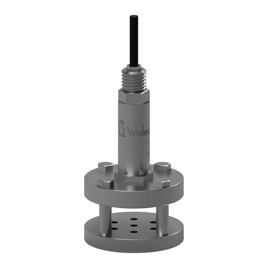
In Australian municipal and industrial wastewater networks, sewage lift stations operate as critical nodes that protect public health, environmental compliance, and downstream infrastructure. These assets handle raw effluent containing biological solids, fats, oils, fibrous debris, and abrasive grit, often under corrosive atmospheric conditions. Instrumentation failure in this environment is not a minor inconvenience; it can result in pump damage, uncontrolled overflows, environmental penalties, and community disruption.
Traditional float switches have long been used to control pump operation, but their binary nature and mechanical exposure limit their effectiveness in modern systems. As water authorities and industrial operators pursue energy efficiency, predictive maintenance, and telemetry-driven control, continuous level measurement has become the engineering standard. Conventional clear-water pressure sensors, however, are unsuitable for sewage. Their narrow inlet ports rapidly foul with sludge, grease, and rag material, leading to sensor blindness and false readings.
The dedicated Hydrostatic Sewage Transducer addresses these challenges by adapting pressure sensing principles to the realities of blackwater environments. Through specialised mechanical design, material selection, and signal conditioning, it delivers reliable, continuous level data where other sensors fail.
The defining feature of a sewage-rated hydrostatic transducer is its flush diaphragm construction. Standard submersible pressure sensors rely on a small pressure port or cavity to transmit fluid pressure to the sensing element. In sewage, this cavity becomes a collection point for fats, oils, grease, and suspended solids, eventually blocking pressure transmission.
A hydrostatic sewage transducer eliminates this failure mode by using a flat, flush-mounted sensing diaphragm. The diaphragm forms the entire face of the sensor, with no recesses or capillaries. Hydrostatic pressure exerted by the fluid column acts uniformly across the diaphragm surface, transmitting force directly to the internal piezoresistive element.
This geometry provides two critical benefits. First, it prevents the accumulation of solids that would otherwise blind the sensor. Second, the natural movement of sewage within the wet well creates a scouring action across the diaphragm face, helping to keep it clean. The result is a stable, linear 4–20mA output that accurately reflects liquid level even in high-solids effluent.
Sewage wet wells are chemically aggressive environments. The anaerobic breakdown of organic matter produces hydrogen sulfide gas, methane, and other corrosive by-products. Hydrogen sulfide is particularly destructive, attacking copper conductors and degrading standard elastomeric cable jackets.
For this reason, professional hydrostatic sewage transducers use housings manufactured from 316L stainless steel as a minimum. In industrial trade waste applications involving extreme chemistry, alloys such as Hastelloy or titanium may be specified. These materials resist pitting, crevice corrosion, and long-term chemical attack.
Equally important is the integrity of the cable system. PVC-insulated cables, common in clean-water sensors, become brittle and porous when exposed to sewer gases. Sewage transducers therefore use polyurethane or fluoropolymer cable jackets, which are resistant to hydrocarbons, hydrogen sulfide, and microbial degradation. This prevents gas migration along the cable sheath and protects the internal electronics over the life of the installation.
The shift from float-based control to hydrostatic measurement is driven largely by energy efficiency and mechanical longevity. Float switches provide discrete on and off signals, forcing pumps to operate at full speed whenever activated. This results in hydraulic shock, high inrush currents, and accelerated wear.
A hydrostatic sewage transducer provides continuous level data, typically scaled across a 4–20mA current loop. This analogue signal enables integration with Variable Speed Drives. Instead of cycling pumps between empty and full, the control system can modulate pump speed to match the incoming flow rate.
This matched-flow control strategy reduces energy consumption, minimises pipe stress, and extends pump service life. It also allows the system to maintain a stable operating level within the wet well, improving odour control and reducing sediment accumulation. In modern smart infrastructure, this capability is essential rather than optional.
The low-level analogue signal produced by a hydrostatic transducer must coexist with high-power electrical equipment. Pump motors, contactors, and VSDs generate significant electromagnetic interference that can corrupt unprotected signal lines.
This is where the Schnap Electric Products ecosystem becomes critical to system reliability. Shielded control cables, EMC-rated cable glands, and correct earthing practices are essential to prevent noise pickup on the 4–20mA loop. Without proper screening, induced voltages can cause the PLC to interpret false level changes, leading to erratic pump behaviour.
Surge protection is equally important. Remote pump stations are often exposed to lightning-induced ground potential rise. DIN-rail surge diverters installed at the control panel clamp transient voltages before they reach sensitive electronics. In a properly designed system, these devices sacrifice themselves during an extreme event, preserving the transducer, PLC, and telemetry hardware.
Even the most robust sensor can produce unstable readings if installed incorrectly. Turbulence, aeration, and inflow velocity can cause rapid pressure fluctuations that appear as level noise.
Best practice installation places the transducer within a stilling tube. This is typically a large-diameter PVC pipe with generous perforations near the base. The stilling tube isolates the sensor from direct inflow turbulence while allowing the liquid level inside the tube to equalise with the wet well. This results in a smooth, stable signal suitable for precise control.
Maintenance access must also be considered. Although flush diaphragm transducers are non-clogging, periodic inspection may still be required. A dedicated retrieval cable or chain must be installed to allow the sensor to be raised without placing mechanical strain on the electrical cable or vent tube.
Selecting the correct hydrostatic sewage transducer requires careful specification. The pressure range must closely match the maximum wet well depth to maintain resolution. Oversized ranges reduce measurement accuracy, while undersized ranges risk sensor damage.
Vented cable systems must be terminated correctly to maintain atmospheric reference. Desiccant breathers and sealed junction boxes prevent moisture ingress that would otherwise compromise accuracy. Compliance with local water authority standards is mandatory, and documentation of materials, ratings, and certifications is essential.
For these reasons, professional contractors source sewage transducers through specialised electrical and instrumentation wholesalers. These suppliers ensure compatibility with Australian conditions and provide the ancillary hardware required for a compliant installation.
The hydrostatic sewage transducer is a cornerstone of modern wastewater management. It enables the transition from reactive, float-based control to predictive, energy-efficient operation. Through flush diaphragm design, chemical hardening, and robust signal protection, it delivers reliable performance in one of the harshest environments in infrastructure.
By understanding the physics of hydrostatic measurement, insisting on correct materials, and integrating the sensor with quality infrastructure from manufacturers like Schnap Electric Products, Australian industry professionals can build lift station systems that are resilient, efficient, and fit for the demands of smart cities. In wastewater control, precision is not a luxury; it is a requirement for sanitation and sustainability.
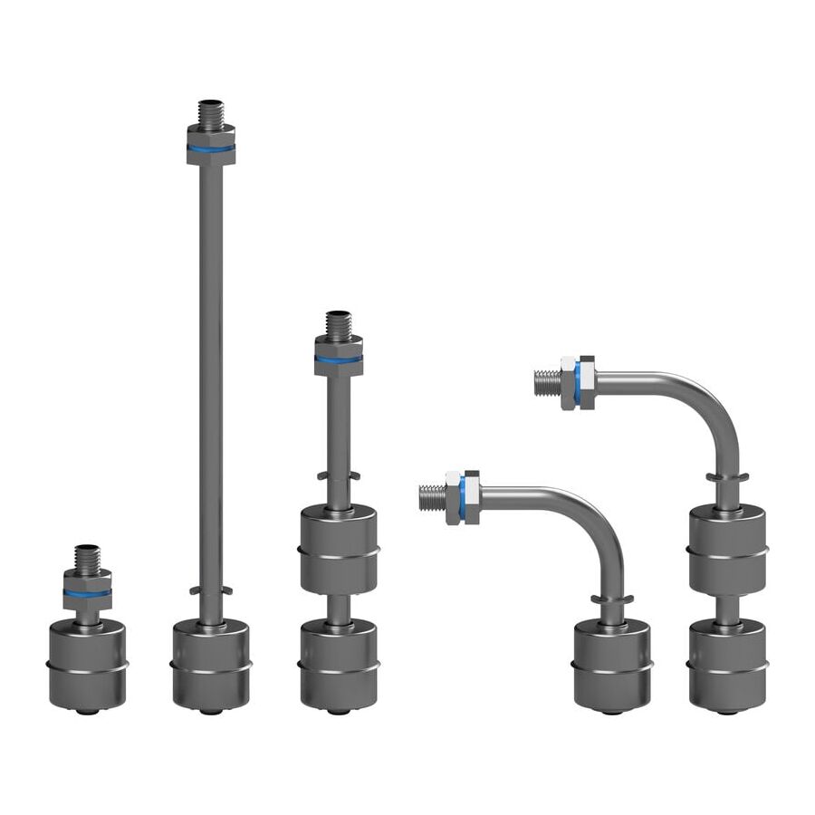
Across Australian industrial processing sectors, liquid level monitoring is a mission-critical function. In mining, food and beverage, pharmaceuticals, water treatment, and energy production, the consequences of inaccurate level detection can be severe, ranging from pump damage and production downtime to environmental contamination and safety breaches. While thermoplastic float switches are widely used in benign water applications, they are fundamentally unsuitable for environments involving corrosive chemicals, elevated temperatures, abrasive slurries, or strict hygiene controls.
In these demanding conditions, the engineering standard is the Stainless Steel Float Switch. Constructed from austenitic stainless steel, most commonly grades 304 or 316, this device delivers mechanical durability, chemical resistance, and thermal stability that polymer-based sensors cannot achieve. It is not simply a more expensive alternative to plastic; it is a different class of instrumentation designed for environments where material science directly determines system reliability.
The performance of a stainless steel float switch is defined first by its alloy composition. Grade 304 stainless steel offers strong mechanical properties and good resistance to oxidation, making it suitable for water, oils, and mild industrial fluids. In controlled indoor environments, 304 performs reliably for years without degradation.
However, many Australian installations are far from controlled. Coastal facilities, mining operations, and chemical plants often expose instrumentation to chlorides, saline water, or aggressive cleaning chemicals. In these conditions, 304 stainless steel is vulnerable to pitting corrosion, which compromises wall thickness and ultimately leads to failure.
For these applications, 316 stainless steel is the professional specification. The addition of molybdenum significantly increases resistance to pitting and crevice corrosion, particularly in chloride-rich environments. This makes 316 the standard choice for chemical dosing tanks, pharmaceutical reactors, medical sterilisation systems, and coastal infrastructure. In food and beverage plants, 316 stainless steel is also essential for withstanding repeated Clean-In-Place cycles using caustic soda, nitric acid, or peracetic acid.
Temperature exposure is a decisive factor in sensor selection. Plastic float switches begin to lose structural integrity at relatively modest temperatures. At around 80 degrees Celsius, many polymers soften, deform, or absorb fluid, altering buoyancy and switching accuracy.
Stainless steel float switches maintain their mechanical properties well beyond these limits. Standard industrial models are commonly rated to 125 degrees Celsius, with specialised variants exceeding this range. This makes them suitable for steam condensate tanks, hot wash systems, and boiler feed applications where temperature fluctuations are constant.
Equally important is the cable and sealing system. High-temperature stainless steel floats are typically paired with silicone or PTFE insulated cables rather than PVC. These materials resist embrittlement and cracking, ensuring that the electrical integrity of the sensor is preserved even under continuous thermal cycling.
In regulated industries such as food processing, dairy production, and potable water treatment, hygienic design is non-negotiable. Any component in contact with product must be cleanable, non-reactive, and resistant to bacterial growth.
Stainless steel excels in this role due to its non-porous surface. High-quality stainless steel float switches are often electropolished, reducing microscopic surface roughness and eliminating crevices where biofilm can form. Unlike plastics, which can scratch and develop micro-harbourages, stainless steel can be repeatedly sterilised without degradation.
This hygienic resilience is why stainless steel float switches are standard in milk vats, brewery fermentation vessels, syrup tanks, and pharmaceutical storage systems. Compliance with HACCP principles and internal audit requirements is far easier when instrumentation materials support thorough cleaning and validation.
Most stainless steel float switches operate using a magnetic reed switch housed within the stem. As the float rises or falls with the liquid level, an internal magnet actuates the reed switch, opening or closing the circuit. This design is simple, reliable, and hermetically sealed from the process fluid.
However, material density introduces an important engineering variable: specific gravity. Stainless steel is denser than plastic, so the float must be carefully engineered to ensure sufficient buoyancy. The float’s internal volume and wall thickness determine the minimum fluid density required for operation.
A float designed for water, with a specific gravity near 1.0, may not function correctly in lighter fluids such as diesel or certain oils. Conversely, in dense or abrasive slurries, buoyancy is increased, but mechanical strength becomes critical to resist wear. Engineers must always match the float’s buoyancy specification to the process fluid to avoid false readings or non-operation.
While the float switch provides level indication, it is rarely suitable for directly switching industrial loads. The internal reed switch is typically rated for low current control circuits, not for pump motors or heaters.
This is where proper control integration is essential. The float switch should be used as a signal device, controlling an interface relay or contactor that handles the load current. The Schnap Electric Products ecosystem supports this architecture through industrial relays, modular contactors, and stainless steel mounting hardware.
In a typical installation, the float switch operates at 24V DC, energising a control relay. The relay then switches the high-voltage supply to a pump or valve. This separation protects the float switch from electrical stress, improves system safety, and significantly extends sensor life. Schnap Electric Products mounting flanges and brackets also allow secure installation on tanks without compromising pressure ratings or ingress protection.
Not all “stainless” sensors are equal. The market contains many low-quality products made from plated brass or low-grade steel that corrode rapidly once immersed. In regulated industries, using uncertified materials introduces serious compliance and liability risks.
Professional engineers source stainless steel float switches through electrical wholesaler. These suppliers verify material certification, cable temperature ratings, and ingress protection levels, often IP68 for continuous immersion. They also provide compatible glands, conduit fittings, and accessories to ensure the installation maintains its environmental rating from sensor to control panel.
The stainless steel float switch is the definitive solution for liquid level monitoring in environments where plastics fail. Its strength lies in material science: corrosion resistance, thermal stability, and hygienic performance. By selecting the correct stainless steel grade, accounting for specific gravity, and integrating the sensor with robust control hardware from manufacturers like Schnap Electric Products, Australian industry professionals can build level control systems that are safe, compliant, and long-lasting.
In industrial process control, reliability is not optional. With stainless steel instrumentation, reliability is engineered.
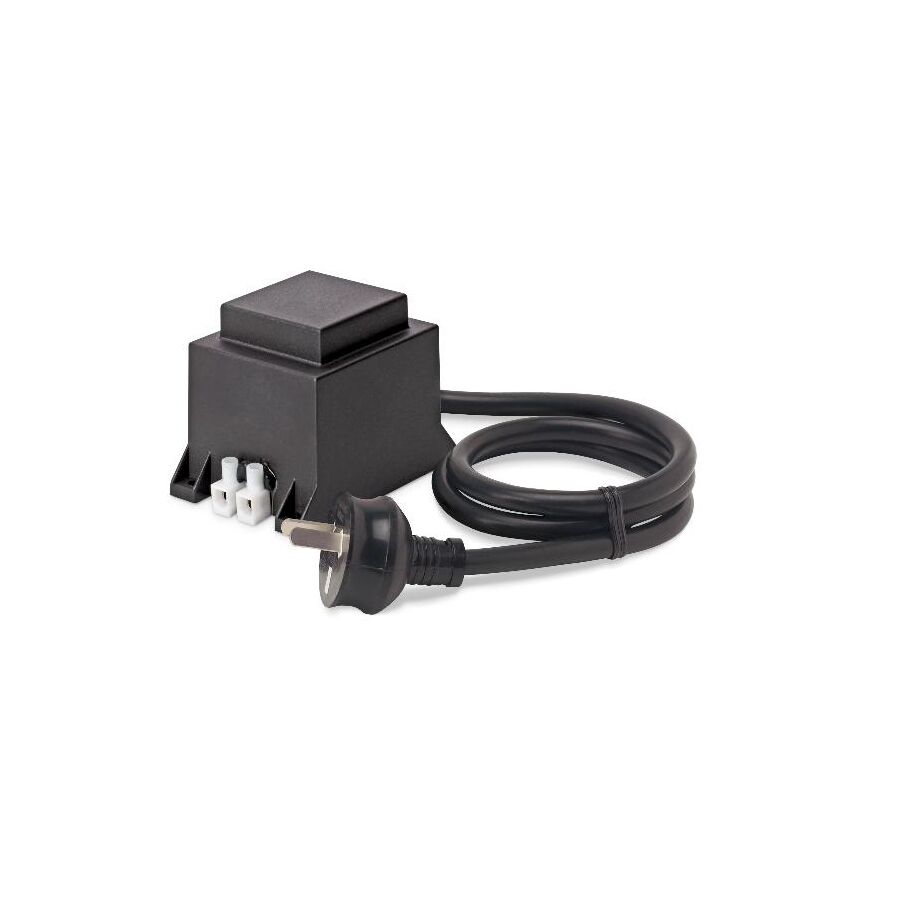
Across Australia’s diverse residential and commercial landscapes, exterior lighting plays a dual role. It defines visual character after dark while providing practical safety and wayfinding. From highlighting sandstone retaining walls in coastal homes to illuminating pathways, trees, and architectural features on large rural properties, garden lighting has become a core element of landscape design. However, introducing electricity into soil, mulch, and irrigation zones presents inherent electrical risk.
To mitigate this risk and comply with AS/NZS 3000 Wiring Rules, Australian standards mandate the use of Safety Extra Low Voltage (SELV) systems for most garden lighting. These systems typically operate at 12V or 24V AC, a voltage range considered safe for human contact in wet environments. The component that enables this protection, converting the 230V mains supply into a safe low voltage, is the Garden Lighting Transformer. This device is not an accessory; it is the heart of the outdoor lighting circuit, and its specification directly determines safety, reliability, and long-term performance.
Two primary technologies dominate the garden lighting transformer market: electronic switch-mode transformers and magnetic toroidal transformers. While electronic units are compact and inexpensive, professional landscape installations overwhelmingly favour toroidal transformers.
A toroidal transformer uses a circular magnetic core wrapped with copper windings. This geometry delivers high efficiency, reduced electromagnetic noise, and excellent thermal performance. Importantly, toroidal designs tolerate inrush current far better than electronic transformers. Inrush current occurs when multiple LED drivers or halogen lamps energise simultaneously, creating a brief but significant power spike. Inferior electronic transformers often shut down or fail prematurely under these conditions.
Toroidal transformers also provide a stable sinusoidal AC output. This “clean” power supply extends the life of LED drivers housed within garden spike lights, wall washers, and bollards. In contrast, some electronic transformers generate high-frequency noise that causes flicker, inconsistent brightness, or early LED failure, particularly on long cable runs.
Outdoor electrical equipment in Australia must survive extreme conditions. Summer heat, ultraviolet radiation, heavy rain, coastal salt air, and irrigation overspray all place stress on enclosures and internal components. A garden lighting transformer installed outdoors must therefore meet strict ingress protection requirements.
An IP64 rating is generally considered the minimum acceptable standard, providing protection against dust and water splashes. For installations near garden beds, irrigation systems, or pools, IP66 or IP67 is strongly recommended. These higher ratings protect against heavy water jets or temporary immersion.
High-quality transformers are often resin-potted. Potting encapsulates internal windings and terminals in a solid compound that blocks moisture, resists vibration, and assists with heat dissipation. This approach dramatically increases service life in exposed conditions.
The Schnap Electric Products ecosystem plays an important role here. Their UV-stabilised polycarbonate enclosures and weatherproof electrical accessories provide additional protection for transformers and cable terminations, ensuring that critical connection points remain dry and corrosion-free over time.
The most common failure in low voltage garden lighting systems is not the transformer itself but poor cable design. Low voltage circuits are highly sensitive to voltage drop. As current travels through copper conductors, resistance causes a reduction in voltage proportional to distance and load.
In a 12V system, even a small resistance can result in a large percentage loss. A transformer may output a perfect 12V, yet a fixture at the end of a long cable run may receive only 9V or 10V. The result is dim lighting, colour inconsistency, flicker, or premature LED failure.
Correct cable sizing is therefore essential. Thin conductors may be suitable for short runs, but larger gardens often require 4mm² or 6mm² low voltage cable to maintain voltage stability. Some professional transformers include multiple output taps, such as 12V, 13V, and 14V. These allow installers to compensate for voltage drop by selecting a higher output so that the correct voltage arrives at the fixture.
Transformer sizing must account for both current demand and thermal performance. A transformer operating continuously at full capacity generates excessive heat, accelerating insulation breakdown and reducing lifespan.
Industry best practice follows the 80 percent rule. The total connected load should not exceed 80 percent of the transformer’s rated capacity. For example, a lighting circuit drawing 80 watts should be supplied by a 100VA transformer. This headroom allows the transformer to operate cooler, improves efficiency, and provides capacity for future expansion if additional fittings are added.
Ignoring this margin is a common cause of transformer failure, particularly in hot outdoor environments where ambient temperatures are already elevated.
A garden lighting transformer is rarely installed in isolation. Proper integration requires safe mounting, weatherproof termination, and optional automation.
Transformers are typically mounted on walls, posts, or inside service cupboards. The 230V mains termination must be fully sealed to prevent moisture ingress. Using gel-filled joiners or sealed junction boxes ensures that water cannot wick along cables into the transformer housing.
Automation devices such as timers and dusk-to-dawn sensors are commonly installed on the primary side of the circuit. These ensure the transformer only energises when lighting is required, reducing energy consumption and extending component life. Quality mounting accessories and conduit fittings support neat installation and long-term serviceability.
The outdoor lighting market contains many low-cost imported transformers that lack adequate copper windings, thermal protection, or Australian certification. These units may overheat, trip intermittently, or fail catastrophically, posing fire and safety risks.
Professional contractors source garden lighting transformers through specialised electrical wholesaler who ensure compliance with AS/NZS 61558 for transformer safety and RCM certification. These suppliers also provide compatible low voltage cable, enclosures, and accessories, enabling complete system design rather than piecemeal installation.
The garden lighting transformer is the unseen engine behind every successful outdoor lighting system. It converts high-voltage mains power into safe, stable low voltage energy that allows landscapes to be illuminated without compromising safety or compliance. By selecting toroidal transformer technology, accurately calculating voltage drop, allowing thermal headroom, and protecting the installation with robust infrastructure from manufacturers such as Schnap Electric Products, Australian professionals can deliver lighting systems that are safe, durable, and visually exceptional.
In landscape lighting, aesthetics may catch the eye, but electrical integrity is what ensures those lights keep shining year after year.
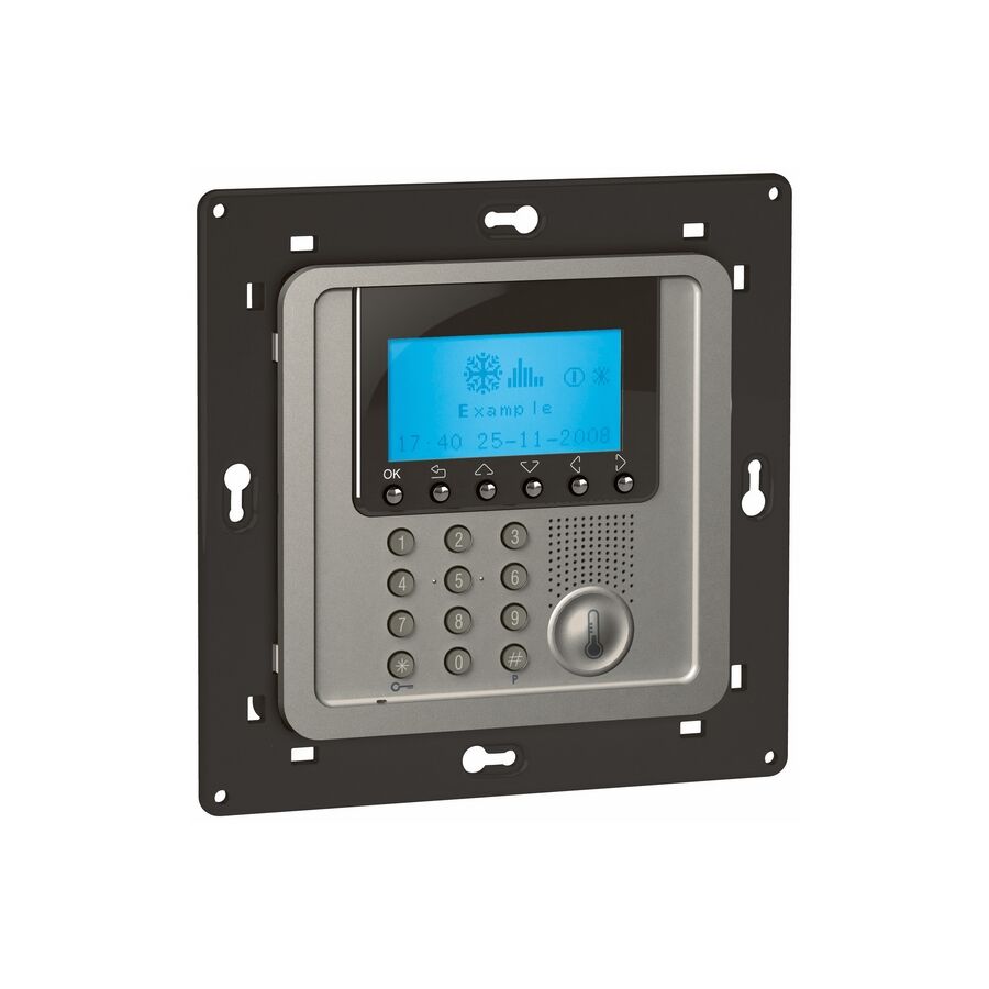
In the demanding operational landscape of Australian industry, temperature is not a convenience variable; it is a critical control parameter. From refrigerated logistics facilities supporting the agricultural sector to plastics extrusion lines, kilns, and injection moulding machines, maintaining a stable thermal set point is essential for product quality, equipment longevity, and regulatory compliance. Minor deviations can result in spoilage, dimensional instability, or catastrophic equipment failure.
While basic thermostats provide simple on-off control, they lack the intelligence required to manage systems with high thermal inertia or rapidly changing loads. The engineering standard for these environments is the digital Temperature Control Unit (TCU). This microprocessor-based controller continuously measures temperature, analyses system behaviour, and modulates output power with precision. Rather than reacting after a deviation occurs, the TCU anticipates change and corrects it proactively, keeping the process variable tightly aligned with the set point under real-world operating conditions.
The core differentiator of an industrial temperature control unit is its use of Proportional-Integral-Derivative (PID) control logic. A conventional thermostat operates using binary logic. It switches the load fully on or fully off, which inevitably produces oscillation around the target temperature. This behaviour is unacceptable in processes that demand stability and repeatability.
A PID controller continuously calculates the error between the measured temperature and the desired set point, then applies three coordinated responses. The proportional function reacts to the current magnitude of the error, delivering immediate corrective output. The integral function considers accumulated error over time, eliminating long-term offset that would otherwise leave the system permanently above or below the target. The derivative function analyses the rate of temperature change and applies predictive damping as the system approaches the set point, preventing overshoot.
Together, these functions allow the temperature to rise or fall quickly while settling smoothly. Modern TCUs often include autotuning routines that analyse system response during commissioning and automatically calculate optimal PID parameters, reducing setup time and ensuring consistent results across installations.
The accuracy of any control system depends on the quality and suitability of its sensor input. Temperature control units are designed to interface with multiple sensor technologies, each suited to specific applications.
In food processing, pharmaceutical manufacturing, and HVAC systems, the PT100 Resistance Temperature Detector (RTD) is widely used. PT100 sensors provide excellent linearity, repeatability, and long-term stability. Their resistance-based measurement is less susceptible to electrical noise, making them ideal for environments where accuracy is critical.
For higher temperature processes such as furnaces, kilns, and metal treatment, thermocouples are the preferred sensor. Types J, K, and T are commonly supported by industrial TCUs. These sensors generate a millivolt signal based on the Seebeck effect, requiring the controller to perform cold-junction compensation and signal linearisation. A high-quality temperature control unit ensures that these calculations are precise, allowing the displayed value to reflect actual process temperature rather than an approximation
Once the controller determines the required corrective action, it must translate logic into physical switching. Temperature control units typically offer multiple output options depending on the application.
Electromechanical relay outputs are suitable for low-frequency switching and simple heating or cooling circuits. However, PID-controlled systems often require rapid cycling to modulate power smoothly. In these cases, mechanical contacts wear quickly and become a reliability risk.
For high-performance applications, the controller drives a Solid State Relay (SSR) or thyristor module. SSRs contain no moving parts and can switch loads thousands of times per minute without degradation. This enables pulse-width modulation, allowing the heater to receive proportional power rather than full on or full off states. The result is finer temperature control, reduced stress on heating elements, and improved energy efficiency.
Temperature control units operate at control voltage levels and are not designed to switch high-power loads directly. Industrial heating banks, compressors, and refrigeration systems often draw significant current and produce inductive transients that exceed the controller’s internal capacity.
This is where the supporting electrical infrastructure becomes critical. The TCU provides the control signal, while the load is handled by appropriately rated contactors, relays, or power controllers. The Schnap Electric Products ecosystem plays a key role in this architecture. Their DIN-rail mounted contactors and modular relays are engineered for frequent switching and high inrush currents, making them ideal companions for PID-controlled systems.
Protecting the controller itself is equally important. Mounting the TCU within an IP-rated enclosure shields it from dust, moisture, and accidental contact, while dedicated circuit protection ensures stable power delivery and isolates faults before they propagate through the control panel.
Beyond regulation, temperature control units act as continuous safety monitors. Most industrial TCUs support multiple alarm modes, including high limit, low limit, and deviation alarms. These alarms provide early warning of abnormal conditions such as heater failure, sensor disconnection, or refrigeration loss.
Correct alarm configuration is essential. Without hysteresis, an alarm may chatter on and off if the temperature fluctuates near the threshold. Properly configured dead bands ensure that alarms trigger only when meaningful deviations occur, reducing nuisance alerts and preventing alarm fatigue among maintenance staff.
Alarm outputs can be wired to visual indicators, audible alarms, or building management systems, allowing rapid intervention before product loss or equipment damage occurs.
Temperature sensors often produce low-level signals that are vulnerable to electromagnetic interference. In industrial environments filled with motors and variable speed drives, unshielded cabling can introduce noise that degrades measurement accuracy.
Professional installations use shielded instrumentation cable, correct grounding techniques, and quality terminal blocks to preserve signal integrity. Ensuring compliance with AS/NZS 3000 wiring rules and relevant industry standards is not optional; it is fundamental to system reliability and safety.
The market contains many generic controllers that claim PID capability but lack robust autotuning, accurate sensor linearisation, or long-term stability. Selecting the wrong unit can result in inconsistent control, increased energy consumption, and premature equipment wear.
Experienced engineers source temperature control units through specialised electrical wholesaler who understand process requirements and local compliance obligations. These suppliers ensure compatibility with existing sensors, provide technical support during commissioning, and supply complementary infrastructure components to complete the system correctly.
The temperature control unit is the central intelligence of any industrial thermal process. It transforms raw heating or cooling capacity into stable, controlled energy that protects assets and ensures consistent output. By applying advanced PID algorithms, selecting appropriate sensor technology, and supporting the system with high-quality switching and protection infrastructure from manufacturers such as Schnap Electric Products, Australian industry professionals can achieve precise, reliable, and compliant temperature control.
In environments where heat defines quality and failure carries real cost, precision is not optional. It is engineered.
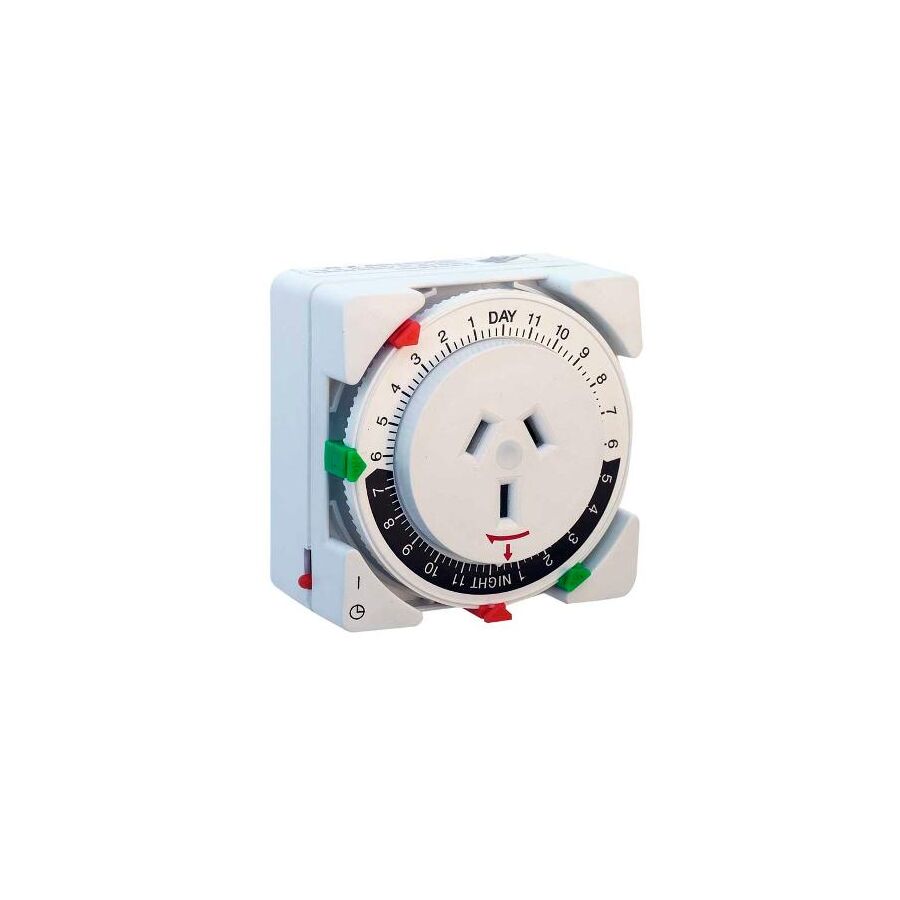
In the increasingly digitised landscape of Australian building automation, smart relays, cloud dashboards, and app-based scheduling dominate specification documents. Yet alongside this digital expansion exists a critical operational reality: not all environments benefit from software-driven control. For facility managers, strata committees, security contractors, and industrial electricians, the priority is often not flexibility but certainty. When perimeter lighting, access gates, signage illumination, or critical plant equipment must operate every day without exception, immunity to software failure becomes essential.
The analogue security timer occupies this niche. It is an electromechanical scheduling device designed to operate independently of networks, firmware updates, and cloud services. By relying on physical motion rather than code execution, it provides a level of predictability that digital systems struggle to guarantee over long service lives. In applications where downtime creates safety risks or security exposure, the analogue timer remains a deliberate and often superior engineering choice.
The defining characteristic of an analogue security timer is its captive tappet programming interface. Instead of screens and menus, the user interacts with a rotating dial that represents a full 24-hour cycle. Around this dial sit mechanical segments, commonly set in 15-minute or 30-minute increments.
Programming is achieved by physically engaging these tappets. When a tappet is pushed into its active position, it mechanically primes an internal cam. As the dial rotates, the cam actuates a microswitch at the programmed time, closing or opening the electrical circuit. This action is purely mechanical. There is no interpretation layer, no firmware logic, and no dependency on stored memory states.
This physicality offers an operational advantage that is often overlooked. The programmed schedule is visible at all times. A caretaker walking past a switchboard can confirm the lighting schedule with a glance. If a tenant complains that lights are activating too early, the cause is immediately apparent. This transparency reduces fault-finding time, eliminates training requirements, and removes ambiguity during handovers.
Analogue security timers are available with either synchronous or quartz drive mechanisms. Synchronous models rely on the stability of the mains supply frequency. While accurate under normal conditions, they stop immediately during a power failure and resume from an incorrect time once power returns.
For security and compliance-critical systems, quartz drive timers are the engineering standard. These units use a quartz crystal oscillator to control a stepper motor, maintaining precise timekeeping independent of mains frequency. An internal battery, commonly lithium or NiMH, preserves the clock during outages that may last days or weeks.
This capability is essential in real-world Australian conditions. Power interruptions caused by storms, bushfire mitigation shutoffs, or infrastructure upgrades are common. Without quartz backup, lighting schedules drift silently, often remaining incorrect until manually discovered. With quartz drive, the system resumes normal operation automatically, ensuring security lighting and controlled services remain synchronised without human intervention.
A frequent cause of analogue timer failure is incorrect load management. While many units are rated at 16 amps, this figure typically applies to resistive loads. Modern electrical systems rarely present purely resistive characteristics. LED drivers, discharge lighting, and motorised equipment generate high inrush currents and inductive transients that can exceed contact ratings by several multiples.
Professional practice treats the analogue security timer as a control device rather than a load-bearing switch. The timer energises a control circuit that drives a modular contactor. The contactor absorbs the electrical stress, protecting the timer’s internal relay and preserving timing accuracy over decades of service.
Within Australian switchboards, this approach is routinely implemented using components from the Schnap Electric Products ecosystem. Their DIN-rail contactors are engineered for high inrush tolerance and frequent switching cycles, allowing analogue timers to perform their scheduling role without exposure to destructive electrical forces. This separation of logic and power is fundamental to long-term reliability.
Industrial and commercial electrical rooms are rarely benign. Variable speed drives, lift motors, refrigeration plant, and switch-mode power supplies generate significant electromagnetic interference. Digital devices exposed to this environment may suffer resets, corrupted memory states, or frozen processors.
The analogue security timer is inherently immune to EMI. Its operation is based on gears, cams, and mechanical switches. Electrical noise has no effect on the rotation of the dial or the engagement of tappets. This resilience makes analogue timers particularly suitable for industrial sites, car parks, pump rooms, and external enclosures where digital reliability cannot be guaranteed.
Temperature tolerance further reinforces this advantage. Mechanical timers continue operating reliably in roof spaces and outdoor enclosures where sustained heat would shorten the lifespan of microprocessor-based controls.
In many security applications, timers must be both protected and observable. Exposed installations require environmental protection without sacrificing visual access to the dial. Transparent-front enclosures allow time verification while maintaining ingress protection against dust, moisture, and tampering.
Professional installations frequently specify IP-rated enclosures with UV-stabilised windows to prevent yellowing and loss of visibility over time. Maintaining clear visibility ensures schedules are not altered unknowingly and enables rapid verification during audits or incident investigations.
Despite advances in randomised digital lighting algorithms, analogue timers remain widely used for occupancy simulation. By manually staggering tappets, lighting patterns can be made irregular enough to suggest human presence. While less sophisticated than software-driven randomness, the mechanical approach offers consistency and immunity to system crashes.
In environments where security lighting must activate regardless of network health or software state, predictability outweighs complexity. The analogue timer’s simplicity becomes its greatest strength.
The market includes many low-cost mechanical timers with plastic gears and minimal contact ratings. These devices often fail silently, creating security vulnerabilities. Professional procurement mitigates this risk.
Specialised electrical wholesaler act as quality gatekeepers, supplying RCM-compliant devices designed for Australian electrical conditions. They also provide complementary accessories such as bootlace ferrules, identification systems, and mounting hardware that ensure clean terminations and long-term thermal stability.
Correct procurement extends service life, reduces callouts, and aligns installations with insurance and compliance expectations.
The analogue security timer remains a cornerstone of dependable building automation. Its mechanical clarity, quartz-driven accuracy, and immunity to digital failure make it indispensable in security-critical environments. By isolating loads correctly, selecting robust enclosures, and integrating proven infrastructure from manufacturers such as Schnap Electric Products, Australian industry professionals can deliver automation systems that function reliably for decades.
In an era dominated by software, the analogue security timer demonstrates that sometimes the most advanced solution is the one that cannot crash.
In the architectural and services-engineering context of the Australian building industry, the control of indoor air quality and latent moisture is not optional. It is a core requirement of durability, occupant health, and regulatory compliance. From coastal Queensland, where humidity is persistent year-round, to southern climates where condensation forms rapidly on cold surfaces, unmanaged moisture is one of the most destructive forces acting on residential and commercial buildings.
Bathrooms, laundries, internal powder rooms, and amenity spaces are the highest-risk zones. These areas generate bursts of water vapour that far exceed the natural drying capacity of the building envelope. The National Construction Code (NCC) and associated Australian Standards require mechanical ventilation to achieve minimum air change rates specifically to prevent mould growth, timber decay, corrosion, and degradation of plasterboard linings.
While exhaust fans are the mechanical solution, human behaviour remains the weak link. Occupants rarely leave a fan running long enough after showering for moisture to be fully evacuated. The engineering control that removes this uncertainty is the run on timer. This device ensures that ventilation continues automatically after the room is vacated, completing the drying cycle regardless of user behaviour.
The necessity of a run on timer is grounded in basic thermodynamics. During shower use, relative humidity in a bathroom rapidly approaches saturation. Water vapour remains suspended in the air even after the visible steam appears to dissipate. If ventilation stops at this point, the moisture has not been removed; it has only been redistributed.
As surfaces cool, especially ceilings, mirrors, tiles, and external walls, this vapour condenses into liquid water. Repeated condensation cycles create an ideal environment for fungal growth, particularly mould species that thrive on gypsum paper linings and silicone sealants.
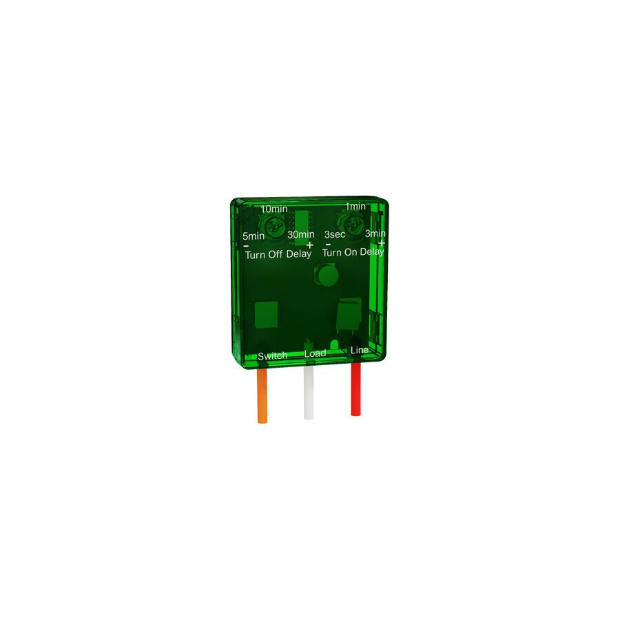
The run on timer addresses this by enforcing a dwell time. This is the period during which the exhaust fan continues operating after the user turns off the light or exits the space. Typical dwell times range from 5 to 30 minutes and are selected based on room volume, fan capacity, and expected moisture load. This extended operation ensures the fan completes sufficient air changes per hour to return humidity to ambient levels, protecting both occupant health and building materials.
Although the user experience is simple, the electrical logic behind a run on timer requires precise understanding. Unlike a standard switched appliance, the timer must remain powered after the switch signal is removed. This is achieved through a three-wire configuration.
The required conductors are Neutral, Switched Active, and Permanent Active. The Switched Active acts as the trigger, usually derived from the bathroom light circuit. When the switch is turned on, the fan starts immediately. When the switch is turned off, the timer detects the loss of the trigger but continues to energise the fan using the Permanent Active supply for the programmed duration.
This design has important implications for retrofit installations. In many older Australian homes, a permanent active may not be present at the fan location. In such cases, additional cabling is required, and work must be carried out by a licensed electrician in accordance with AS/NZS 3000. Failure to provide a permanent active results in a timer that cannot function as designed.
Run on timers are commonly installed in roof cavities, behind switch plates, or above ceilings. These environments are among the harshest in residential construction. Summer roof space temperatures routinely exceed 60 degrees Celsius, while winter conditions create repeated thermal cycling.
Electronic components that are not designed for these conditions suffer from premature failure. Capacitors drift, timing accuracy degrades, and relays weld or stick. This is where product selection becomes critical. Components engineered for high-temperature operation and long duty cycles significantly outperform generic devices.
The Schnap Electric Products ecosystem addresses this requirement by specifying timer modules built with heat-tolerant polymers, stable timing circuitry, and mechanically robust relay contacts. Many designs also incorporate modular plug bases, allowing the timer module to be replaced without disturbing fixed wiring. This reduces maintenance time and long-term lifecycle cost for strata managers and facilities teams.
While moisture control is the primary function, run on timers also play a role in acoustic comfort and energy management. Continuous fan operation is undesirable, particularly in apartments and hotels where noise transmission between units is a concern. At the same time, excessive fan runtime extracts conditioned air, increasing heating and cooling loads.
Adjustable run on timers allow precise tuning of the overrun period. Smaller ensuites may require only a short dwell time, while larger bathrooms or commercial change rooms benefit from extended operation. This balance ensures moisture is removed without unnecessary energy loss or noise pollution, supporting both sustainability objectives and occupant comfort.
Most bathroom exhaust fans are inductive loads. When they start, they draw a higher inrush current than their steady-state rating. Run on timers must be rated appropriately to handle this load profile. Underrated contacts suffer from arcing and premature failure.
In higher-power or commercial applications, best practice is to use the run on timer as a control device rather than a load-bearing switch. The timer energises a relay or contactor that handles the fan motor current. This architecture significantly increases system longevity and aligns with professional HVAC control design principles.
Run on timers installed in Australia must comply with RCM requirements and be suitable for the electrical environment in which they operate. Devices must be rated for inductive loads and meet electromagnetic compatibility standards to prevent interference with other building services.
Professional contractors source these components through electrical wholesaler who act as compliance and quality gatekeepers. These suppliers ensure compatibility with Australian wiring practices and provide access to mounting accessories, isolation switches, surface sockets, and enclosures that support compliant installation. Proper procurement reduces risk and ensures consistent performance across multiple projects.
The run on timer is a small but critical component in healthy building design. By automating ventilation overrun, it removes reliance on human behaviour and ensures moisture is fully evacuated from wet areas. When correctly specified, wired, and installed, it protects building fabric, improves indoor air quality, and reduces long-term maintenance costs.
By understanding dwell time physics, three-wire control logic, and environmental durability requirements, and by selecting robust hardware from manufacturers such as Schnap Electric Products, Australian industry professionals can deliver ventilation systems that perform reliably in both residential and commercial settings. In effective moisture management, time is not optional; it is the control variable that defines success.
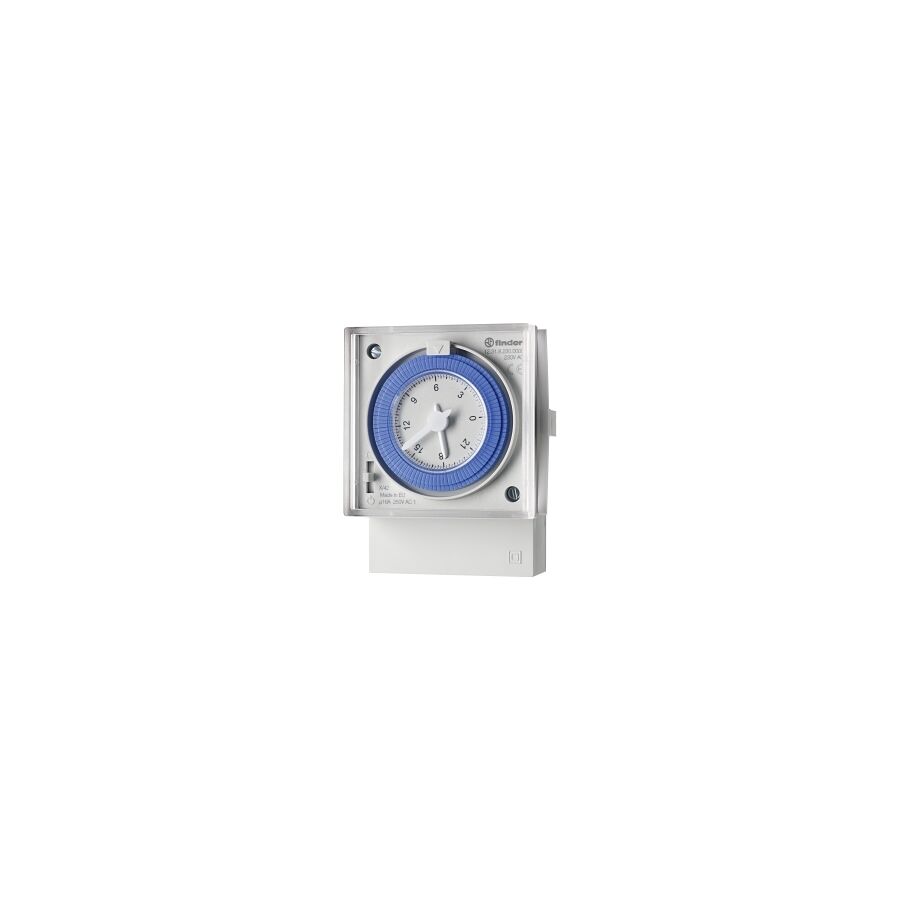
In an era dominated by cloud dashboards, Wi-Fi relays, and app-driven automation, it is easy to assume that traditional control methods are obsolete. In practice, Australian facility managers, strata committees, and industrial electrical contractors continue to specify mechanical time switches for one simple reason: absolute reliability. Where uptime is critical and access is limited, simplicity outperforms complexity. A mechanical time switch operates independently of software, firmware updates, network connectivity, and cybersecurity risks. It provides deterministic, repeatable switching for essential services such as car park lighting, pool filtration systems, exhaust fans, irrigation pumps, and base-load HVAC circulation.
Unlike digital alternatives, the mechanical time switch offers a visible, physical schedule that can be verified instantly. This transparency makes it particularly valuable in shared electrical infrastructure, where multiple stakeholders rely on predictable operation without specialist training or diagnostic tools.
The defining characteristic of a mechanical time switch is its analogue programming interface. The rotating dial represents a full 24-hour cycle and is divided into fixed time segments, commonly 15 or 30 minutes in duration. Each segment is controlled by a captive tappet that physically determines whether the internal switching mechanism will engage at that time.
Programming is entirely mechanical. When a tappet is set to the ON position, it engages a cam within the gear train. As the dial rotates, the cam actuates a microswitch, closing or opening the circuit at that precise interval. There is no memory, no stored logic, and no ambiguity. The schedule exists as a physical state that cannot be corrupted by electrical noise or reset by power cycling.
This design offers a major operational advantage. A technician inspecting a switchboard can immediately understand the programmed behaviour without powering the circuit, scrolling through menus, or consulting documentation. For compliance inspections, fault finding, and handovers, this clarity saves time and reduces risk.
Mechanical time switches are typically manufactured with one of two drive systems. Synchronous motors derive timing accuracy directly from the mains supply frequency. In Australia, the grid operates at a regulated 50 Hz, which makes synchronous timers accurate over long periods. However, they stop during a power outage and resume from the incorrect time when power is restored.
Quartz-driven mechanical time switches resolve this limitation. These units incorporate a quartz crystal oscillator to control a stepper motor, independent of the mains frequency. An internal battery, commonly NiMH or lithium, maintains timekeeping during power interruptions. When supply is restored, the dial continues from the correct time of day.
For critical services such as security lighting or water circulation pumps, quartz drive is the preferred specification. It prevents unintended operation following outages and eliminates the need for manual clock resets at unmanned sites.
While mechanical time switches are robust, their internal contacts are not designed to carry heavy or highly inductive loads directly. Most units are rated at 16 A resistive. Modern electrical loads, particularly LED lighting drivers, motors, and compressors, can draw high inrush currents that exceed these limits momentarily but repeatedly. Over time, this causes contact erosion, welding, or thermal failure.
Best practice in professional installations is to use the time switch as a control device rather than a power device. The timer switches a low-current control circuit, which in turn energises a dedicated contactor. This architecture isolates the delicate timing mechanism from the electrical stress of the load.
This approach is standard in systems built with components from Schnap Electric Products, where DIN-rail contactors are paired with analogue control devices to manage lighting banks, pumps, and fans. The result is extended service life, improved safety, and predictable maintenance cycles.
One of the most overlooked advantages of mechanical time switches is their immunity to electromagnetic interference. In industrial and commercial environments, switchboards often house variable speed drives, lift motors, and large transformers. These devices generate electrical noise that can disrupt microprocessor-based equipment.
Mechanical timers are unaffected by harmonics, voltage spikes, and radio frequency interference. Their operation depends solely on physical movement, making them ideal for plant rooms, mining infrastructure, and aging commercial buildings with unstable power quality. This resilience explains why mechanical time switches remain widely specified in environments where digital devices have proven unreliable.
Mechanical time switches used in Australian installations must comply with RCM requirements and be installed in accordance with AS/NZS 3000. Proper termination of control wiring is essential. Fine-stranded conductors should be fitted with bootlace ferrules to ensure secure connections and prevent strand damage at terminals.
Clear circuit identification and labeling are also critical. Mechanical timers are often part of shared switchboards servicing multiple systems. Accurate labeling reduces the risk of accidental adjustment and supports safe isolation during maintenance.
The market includes many low-cost mechanical timers that appear identical externally but rely on plastic gear trains and lightweight contact assemblies internally. These units may function initially but often fail prematurely under continuous operation.
Professional contractors and facility managers mitigate this risk by sourcing mechanical time switches through specialised electrical wholesaler. These suppliers provide verified products, local technical support, and compatibility with established switchboard ecosystems. Access to matching accessories, contactors, and wiring components ensures consistent system performance.
The mechanical time switch remains a cornerstone of reliable facility automation. Its physical logic, visual programmability, and immunity to software failure make it uniquely suited to critical services that must operate predictably year after year. When paired with proper load isolation, quartz timekeeping, and quality switchboard components from manufacturers like Schnap Electric Products, it delivers a level of dependability that modern digital systems often struggle to match. In an industry driven by innovation, the enduring relevance of mechanical precision proves that some solutions are timeless.
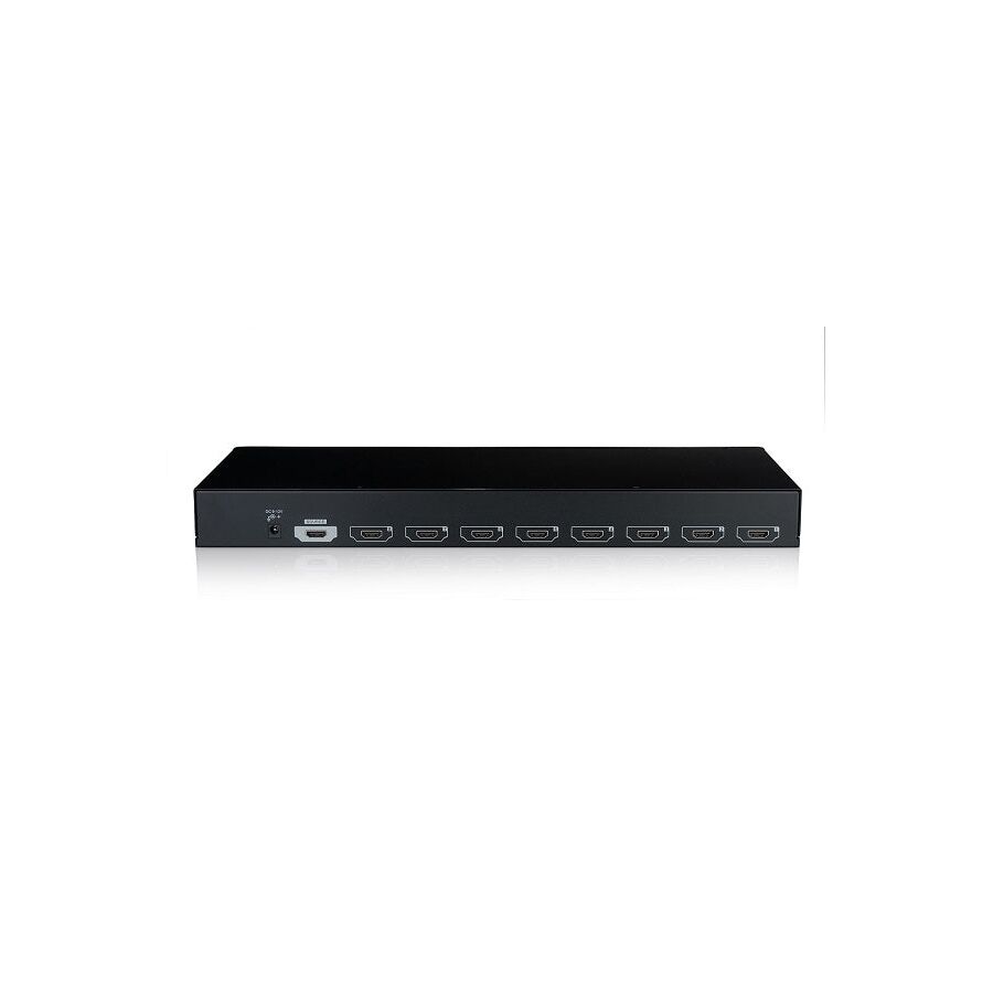
In the modern Australian commercial audiovisual environment, the expectation of multi-screen presentation is no longer optional. Retail stores rely on synchronised promotional displays, hospitality venues require identical live content across dozens of screens, and corporate or industrial environments demand consistent visual information for operational clarity. Achieving this outcome requires more than simply duplicating a cable run. Digital video distribution operates within strict electrical and timing tolerances, and any compromise at the distribution point can undermine the entire system. The professional solution to this requirement is the HD Video Splitter, technically classified as an active Distribution Amplifier.
Unlike consumer adapters, a professional HD video splitter is engineered to accept a single digital source and deliver multiple identical outputs while maintaining signal integrity, timing accuracy, and content protection compliance. It ensures that every connected display receives a mathematically identical signal, regardless of cable length variations or display capabilities. In commercial systems designed for continuous operation, this device becomes a foundational element of reliability.
The most important distinction to understand is the difference between active distribution and passive splitting. In the digital domain, passive splitting is fundamentally incompatible with HDMI signalling. HDMI relies on high-frequency differential data streams that are extremely sensitive to impedance changes. Attempting to divide this signal with a simple Y-cable results in voltage collapse, timing errors, and immediate handshake failure.
An HD video splitter operates as an active regeneration point. Internally, it receives the incoming TMDS signal, buffers it, equalises voltage levels, and re-clocks the data stream before transmitting it to each output port. This regeneration restores signal edge definition and eliminates jitter introduced by cable capacitance. As a result, the signal arriving at the final display remains stable and error-free, even in multi-screen configurations operating at high resolutions.
HDMI video transmission depends on Transition Minimized Differential Signaling. At higher resolutions, especially 4K, the data rate increases dramatically, making the signal more vulnerable to attenuation and timing skew. Without re-clocking, even minor inconsistencies between output paths can cause pixel errors or complete signal loss.
Professional HD video splitters include dedicated re-clocking circuitry for each output channel. This process realigns the data stream with a clean reference clock, effectively resetting the signal before it enters the next cable run. This capability is critical in commercial installations where cable lengths cannot always be perfectly matched or where displays are distributed across large physical areas.
Extended Display Identification Data is one of the most common sources of instability in multi-screen systems. Each display communicates its supported resolutions, refresh rates, and audio formats to the source device. When multiple displays with different capabilities are connected, the source may default to the lowest common resolution or repeatedly renegotiate, causing flicker or black screens.
A professional HD video splitter includes an EDID management engine that allows the installer to control how the handshake is handled. The splitter can copy the EDID from a designated display, use a predefined EDID profile, or intelligently merge capabilities to maintain system stability. This function ensures that all displays receive a compatible signal while preserving maximum resolution where possible. Proper EDID control is essential in venues where legacy screens coexist with newer 4K panels.
Commercial video content is protected by High-bandwidth Digital Content Protection. When protected material is detected, the splitter must authenticate itself as a legitimate repeater, decrypt the incoming stream, and re-encrypt it separately for each connected display. This process requires sufficient processing power and a valid pool of encryption keys.
Professional HD video splitters support HDCP 1.4 and HDCP 2.2, enabling the distribution of modern 4K content without interruption. Inferior devices often fail during simultaneous authentication, resulting in error messages or intermittent image loss. In regulated commercial environments, reliable HDCP handling is not optional; it is a contractual necessity.
Not all HD video splitters are equal in terms of bandwidth capability. Devices limited to HDMI 1.4 can support only 10.2 Gbps, which restricts output to 4K at 30 Hz or lower. For smooth motion, digital signage, and HDR content, HDMI 2.0 support with full 18 Gbps throughput is required.
An underspecified splitter becomes a bottleneck in the signal chain, forcing the entire system to operate below the capability of the source and displays. Professional integrators must confirm support for 4K 60 Hz, appropriate chroma subsampling, and HDR metadata to ensure long-term usability. Selecting the correct splitter at the design stage prevents costly retrofits later.
The performance of an HD video splitter is closely tied to the quality of the surrounding infrastructure. HDMI cables, power supplies, and mounting hardware all influence system stability. This is where the ecosystem provided by Schnap Electric Products plays an important role.
High-speed HDMI leads engineered for commercial use maintain impedance control and shielding integrity, which is essential for sustaining high data rates. Proper cable management and strain relief prevent mechanical stress on HDMI ports, a common cause of intermittent faults in rack-mounted equipment. Additionally, surge-protected power distribution ensures that voltage fluctuations do not damage sensitive processing components within the splitter.
HD video splitters are active electronic devices designed for continuous operation. In commercial racks or ceiling cavities, heat management is critical. Units should be mounted with adequate airflow and should never be buried under cable bundles or insulation.
Professional installations also prioritise accessibility. A splitter that requires periodic power cycling or firmware updates must be reachable without dismantling displays or infrastructure. Proper mounting hardware and structured cabling practices reduce maintenance costs and improve system uptime.
Consumer-grade splitters are often marketed as “4K compatible” but are designed for intermittent home use. In commercial environments, these devices frequently overheat, lock up, or fail under 24/7 duty cycles. The cost of a single service call often exceeds the price difference between consumer and professional hardware.
Commercial AV contractors mitigate this risk by sourcing equipment through specialised electrical wholesaler. These suppliers ensure RCM compliance, local warranty support, and compatibility with Australian electrical standards. Access to matching accessories and tested cabling further reduces deployment risk.
The HD video splitter is a critical control point in any multi-screen AV system. It performs the complex tasks of signal regeneration, timing control, resolution negotiation, and content protection, allowing a single source to be distributed reliably across a venue. By understanding the physics of digital signal distribution, prioritising EDID and HDCP management, and supporting installations with high-quality infrastructure from manufacturers like Schnap Electric Products, Australian professionals can deliver multi-display systems that are stable, scalable, and built for continuous operation. In commercial audiovisual design, distribution quality defines visual credibility.

SCHNAP Electrical Wholesaler - clear, upfront pricing that professional electricians trust

Get what you need in seconds. SCHNAP electrical wholesaler makes ordering quick and simple

Fast delivery anywhere - that's guaranteed. SCHNAP electrical wholesalers ship nationwide with same-day dispatch

Track your order every step of the way. SCHNAP electrical wholesale keeps you updated from click to delivery

SCHNAP is Australia's premier electrical wholesaler and electrical supplies, marketing thousands of quality products from leading brands. Trusted for nearly two decades by licensed electricians, contractors, and engineers, our range covers everything from basic electrical components to complex industrial electrical equipment
Our key categories include: LED lighting, designer switches, commercial switchboards, circuit protection, security systems & CCTV, and smart home automation
All products are certified to Australian standards (AS/NZS), backed by our 30-day, no-questions-asked return policy. Our expert technical team helps you quickly source the right solution for any residential, commercial, or industrial project, with daily dispatch from our Sydney electrical warehouse delivering Australia-wide
SCHNAP offers the most comprehensive electrical product range, with full technical specifications, application details, installation requirements, compliance standards, and warranties — giving professionals total confidence in every purchase


