




Kingsgrove Branch:
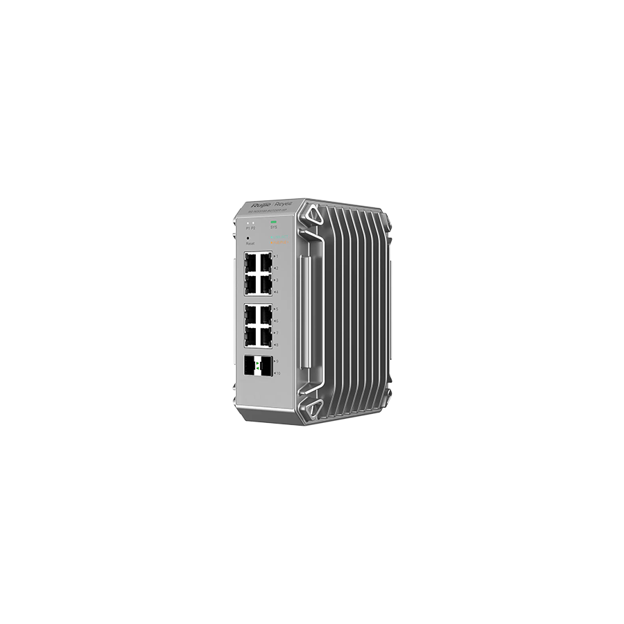
In Australian heavy industry, network reliability is not a convenience. It is a prerequisite for safe and continuous operation. From iron ore processing plants in the Pilbara to refrigerated logistics centres, water treatment facilities, and rail signalling corridors, modern operations depend on real-time data exchange between machines. As Industrial Internet of Things systems merge with traditional Operational Technology, the volume and speed of data at the network edge have increased dramatically. Legacy 10/100 Mbps networks are no longer capable of supporting modern automation, video inspection, and diagnostics.
Deploying standard office networking hardware in these environments is a fundamental engineering mistake. Commercial switches are designed for air-conditioned server rooms, not dust-laden cabinets, vibration-prone machinery, or extreme temperature swings. The industrial gigabit network switch exists specifically to bridge this gap. It delivers high-bandwidth Ethernet performance while withstanding mechanical stress, electrical noise, and thermal extremes commonly found on Australian industrial sites.
One of the most critical differences between industrial and commercial switches is the cooling strategy. In industrial environments, active cooling fans are a liability. Dust, metallic particles, and airborne contaminants are drawn into the device, leading to blocked airflow, electrical shorts, and premature failure.
Industrial gigabit switches use fanless thermal architecture. Heat generated by the internal processor, switching fabric, and power circuitry is transferred directly into a heavy-duty metal chassis. The enclosure itself acts as a heat sink, dissipating thermal energy through passive convection. This design allows continuous operation across extreme temperature ranges, often from minus forty degrees to plus seventy-five degrees Celsius. In remote roadside cabinets, mining control rooms, or outdoor enclosures, this wide operating range ensures the network remains stable during peak heat events and overnight cold cycles.
Industrial control systems rarely rely on a single power source. Network components must align with this philosophy. Unlike office switches powered by a single AC adaptor, industrial switches are designed for direct connection to DC control power.
High-grade industrial gigabit switches feature dual redundant power inputs. If the primary DC supply fails, the switch instantly transfers to the secondary input without dropping packets or resetting the device. This capability is essential in process control environments where even brief communication loss can trigger alarms, shutdowns, or safety interlocks. Input voltage ranges are typically broad, allowing operation from common industrial supplies such as 12V, 24V, or 48V DC. This flexibility supports integration with battery systems, uninterruptible power supplies, and redundant control transformers.
Industrial networks are frequently installed in environments subject to constant vibration and shock. Mining conveyors, rail infrastructure, mobile plant, and heavy machinery all introduce mechanical stress that can loosen connectors and damage delicate components.
Industrial gigabit network switches are engineered to withstand high shock and vibration ratings. Ethernet ports feature robust retention mechanisms, and internal components are secured to prevent movement. The preferred mounting method is DIN-rail installation. This allows the switch to be locked securely alongside PLCs, relays, and power supplies within the control cabinet. Metal DIN-rail clips provide long-term mechanical stability, even in applications where vibration is continuous.
In office networks, physical loops are avoided due to the risk of broadcast storms. In industrial automation, loops are deliberately engineered to increase resilience.
Industrial switches support fast redundancy protocols designed for deterministic recovery. Devices can be connected in ring or line topologies that automatically reconfigure when a fault occurs. If a cable is damaged or a switch fails, traffic is rerouted in milliseconds, often faster than a controller scan cycle. This rapid self-healing behaviour ensures that communication between controllers, sensors, and operator interfaces continues uninterrupted, even after physical damage to the network infrastructure.
Factories, mines, and transport systems generate significant electromagnetic interference. Variable speed drives, high-current motors, welding equipment, and switching devices can inject noise into data cabling and power lines.
Industrial gigabit switches are designed with enhanced electromagnetic immunity. Internal circuit boards are often conformally coated to protect against moisture and conductive dust. Metal housings provide shielding, and proper earthing paths allow noise to be safely dissipated. Effective grounding is essential to maintaining signal integrity and preventing erratic network behaviour in electrically noisy environments.
The switch itself is only one part of the system. The surrounding infrastructure determines whether it can operate reliably over time. Maintaining cabinet ingress protection ratings, managing cable strain, and ensuring correct earthing are all critical factors.
This is where industrial installation accessories from Schnap Electric Products are commonly specified. Heavy-duty cable glands protect Ethernet and power cables as they enter the enclosure. Slotted wiring duct and ferrules ensure secure, low-resistance power connections. Proper cable management reduces stress on terminals and maintains airflow within the cabinet, extending the service life of all installed equipment.
Not all products marketed as industrial networking hardware meet true industrial standards. Some devices are simply commercial switches housed in metal enclosures, lacking proper isolation, coating, or certification.
For Australian deployments, compliance with local electrical and regulatory requirements is essential. Procuring industrial gigabit switches through reputable wholesalers ensures access to genuine hardened equipment with verified performance ratings and regulatory approval. These suppliers also provide compatible power supplies, earthing accessories, and enclosure hardware to support compliant installations from end to end.
The industrial gigabit network switch is a cornerstone of modern automation and Industry 4.0 systems. It enables high-speed data exchange in environments that destroy conventional networking hardware. Through fanless cooling, redundant DC power, vibration-resistant construction, and rapid network recovery, it delivers the resilience required for Australian industrial operations. When combined with robust physical infrastructure and compliant installation practices, it forms a network backbone that matches the durability of the machinery it supports. In industrial networking, uptime is not measured in convenience. It is measured in operational survival.
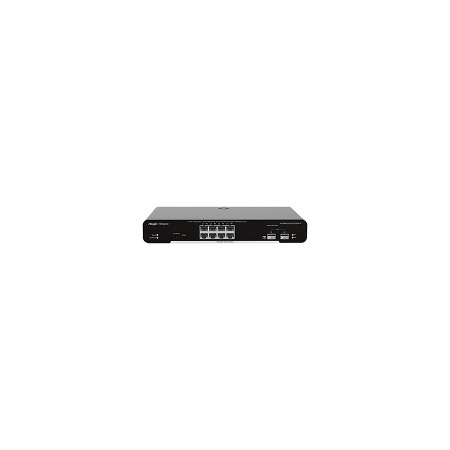
In the modern Australian enterprise, data is the primary operational asset. From cloud-hosted accounting platforms and enterprise resource planning systems to real-time collaboration tools and IP-based telephony, business productivity is directly linked to network performance. As bandwidth demands increase, the limitations of unmanaged network hardware become immediately apparent. While basic switches provide simple connectivity, they lack the intelligence required to control traffic flow, isolate risks, and guarantee consistent performance. The gigabit managed network switch addresses these limitations by introducing structured control, visibility, and resilience into commercial network environments.
A managed switch operates as more than a packet forwarder. It functions as a policy enforcement point within the network, allowing administrators to define how data moves, which devices can communicate, and which services receive priority. In Australian offices, warehouses, retail chains, and industrial facilities, this level of control is no longer optional. It is fundamental to security, uptime, and predictable application performance.
One of the most important capabilities of a managed switch is support for Virtual Local Area Networks. In an unmanaged network, every connected device shares the same broadcast domain. This flat topology increases security exposure and generates unnecessary broadcast traffic that degrades performance.
With VLAN support, a single physical switch can be divided into multiple logical networks. Each VLAN operates as an isolated environment, even though it shares the same hardware. Financial systems, staff workstations, guest Wi-Fi, building automation, and CCTV systems can all be separated into distinct segments. This prevents unauthorised lateral movement between systems and limits the spread of malware. It also reduces broadcast traffic by ensuring packets remain within their assigned VLAN, preserving bandwidth and reducing CPU load on connected devices.
As user counts and data volumes grow, single gigabit uplinks between switches can become a bottleneck. A floor switch supporting dozens of users may overwhelm a single connection to the core switch during peak activity. Managed switches solve this issue through Link Aggregation Control Protocol.
Link aggregation allows multiple physical Ethernet ports to be combined into a single logical connection. This increases total available bandwidth while also providing redundancy. If one link fails, traffic is automatically redistributed across the remaining links without service interruption. In Australian commercial environments where downtime results in lost revenue and operational disruption, this resilience is essential.
Modern networks carry a mix of traffic types with very different performance requirements. Email and file transfers tolerate small delays, but voice and video traffic do not. Without prioritisation, time-sensitive services can suffer from latency, jitter, and packet loss.
Managed switches implement Quality of Service mechanisms to classify and prioritise traffic. Voice and video packets are identified and placed ahead of bulk data transfers in transmission queues. This ensures that real-time applications maintain consistent performance even during periods of heavy network load. For businesses relying on VoIP, video conferencing, and unified communications, QoS is critical to maintaining professional service quality.
Digital signage, IPTV, and streaming services are increasingly common in Australian retail, hospitality, and corporate environments. These applications often rely on multicast traffic. Without management, multicast streams are treated like broadcast traffic and forwarded to every port, wasting bandwidth.
IGMP snooping allows the switch to monitor multicast group membership and forward streams only to ports that have explicitly requested them. This targeted delivery conserves bandwidth and ensures that high-definition video streams scale efficiently without degrading overall network performance.
While the managed switch provides intelligence, its performance and longevity depend heavily on the physical environment. High port densities and continuous operation generate heat, making airflow management essential. Poor cable organisation restricts ventilation and complicates maintenance.
Structured rack layouts using professional cable management solutions help maintain airflow and simplify troubleshooting. Power quality is equally important. Voltage spikes and electrical noise can damage sensitive networking equipment. Proper power distribution with surge protection ensures stable operation and protects the internal switch fabric.
This is where integrated infrastructure components from Schnap Electric Products are commonly specified. Rack-mounted power distribution units, cable managers, and patch panels support clean installations and long-term reliability in commercial network deployments.
A defining advantage of a managed switch is visibility. Through Simple Network Management Protocol, switches report detailed operational data to central monitoring platforms. Administrators can track bandwidth usage, port errors, device status, and thermal conditions in real time.
This proactive insight allows IT teams to identify issues before they impact users. Faulty cables, misconfigured devices, or abnormal traffic patterns can be addressed early, reducing downtime and improving overall network stability. In large Australian organisations, this level of monitoring is essential for maintaining service continuity.
Not all switches marketed as “smart” or “managed” provide the same level of control. Some offer limited web interfaces but lack advanced features such as full VLAN control, CLI access, or robust monitoring. Selecting appropriate hardware requires careful evaluation of technical specifications rather than marketing terms.
In Australia, network equipment must also comply with local regulatory requirements. Procuring managed switches through reputable electrical wholesaler ensures access to compliant hardware, local warranty support, and compatible accessories such as fibre transceivers. These suppliers also provide technical guidance to ensure the final installation meets performance and compliance expectations.
The gigabit managed network switch is a foundational element of modern Australian commercial infrastructure. It transforms the network from a passive transport layer into an intelligent, secure, and resilient system. Through VLAN segmentation, link aggregation, traffic prioritisation, and proactive monitoring, managed switches deliver predictable performance and strong security. When supported by well-designed physical infrastructure and compliant power solutions, they enable organisations to scale confidently in an increasingly data-driven environment. In contemporary networking, intelligence is not an enhancement. It is a requirement for sustainable growth and operational reliability.
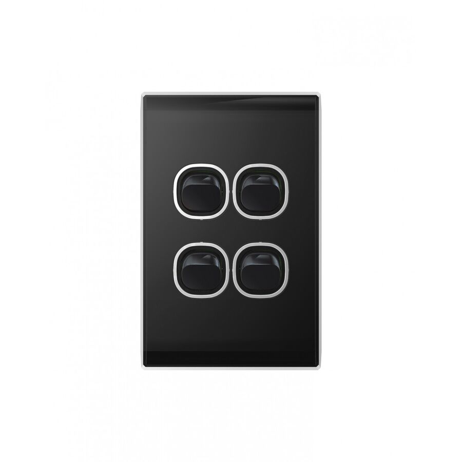
In modern Australian residential and commercial interiors, lighting design has moved well beyond basic illumination. Open-plan living areas, designer kitchens, retail spaces, and offices now rely on layered lighting systems to create mood, improve usability, and define zones. Downlights, pendants, feature strips, wall washers, and external lighting are often controlled independently. Managing these multiple circuits without cluttering walls with numerous switch plates requires a compact and logical control solution. The 4 gang switch has become the industry standard for this purpose, allowing four independent electrical loads to be controlled from a single wall location while maintaining a clean architectural finish.
A 4 gang switch typically fits on a standard Australian mounting centre and replaces what would otherwise require four separate switch plates. This approach improves aesthetics, simplifies user interaction, and aligns with contemporary interior design expectations. For electricians, builders, and specifiers, the device represents a balance between electrical performance, compliance, and visual restraint.
Modern 4 gang switches are no longer manufactured as single moulded units. Most professional-grade systems use a modular grid plate architecture. This construction consists of a metal or reinforced plastic grid plate fixed to the wall bracket, individual switch or control mechanisms clipped into the grid, and a fascia that covers the assembly and conceals fixings.
This modular approach offers significant flexibility. Electricians can configure each position independently, combining standard 10 amp switches, dimmers, fan controllers, or auxiliary mechanisms within one plate. Layouts may be arranged in a two-by-two grid or a horizontal row depending on the series. The grid plate provides mechanical stability, while the fascia ensures a uniform appearance across all controls. This design also simplifies maintenance, as individual mechanisms can be replaced without disturbing the entire assembly.
Although most switch mechanisms are rated at 10 amps, real-world electrical loads require closer analysis. Modern lighting circuits are dominated by LED drivers rather than resistive incandescent lamps. LEDs introduce a phenomenon known as inrush current. When first energised, LED drivers draw a very high instantaneous current as internal capacitors charge. This surge can be many times greater than the normal operating current.
In a 4 gang configuration, multiple LED circuits may be switched on at the same time. If the switch mechanisms are not designed to tolerate these current spikes, contact arcing can occur. Over time, this arcing degrades the contacts, leading to premature failure or welded contacts that remain permanently on. Professional switch mechanisms are designed with enhanced contact materials and ratings to handle capacitive and inductive loads. Selecting mechanisms tested for LED compatibility is critical for long-term reliability in modern installations.
Installing a 4 gang switch introduces physical wiring challenges that must be carefully managed. Four switched actives, common loop feeds, neutrals where required, and earth conductors must all fit within a single wall box or bracket. Under AS/NZS 3000 wiring rules, cables must not be compressed, sharply bent, or damaged during installation. Excessive cable density can place stress on insulation and terminals.
Best practice involves careful cable dressing and the use of mechanisms with dedicated looping terminals or approved connectors. Looping the active feed across multiple mechanisms must be done securely to ensure consistent contact pressure and long-term electrical integrity. Mechanism depth is also critical. Shallow mechanisms allow additional room for conductors and reduce the risk of the assembly being forced out when the fascia is installed.
Many 4 gang switch locations incorporate more than simple on-off control. Ceiling fans, dimmable lighting, and feature lighting zones are often grouped together for convenience. Integrating dimmers and fan speed controllers within a single plate requires careful planning.
Rotary dimmers and electronic fan controllers are physically larger than standard switch mechanisms. Some faceplate designs do not allow adjacent dimmers due to spacing constraints. Heat generation is another factor. Dimmers dissipate heat during operation, and when multiple dimmers are installed side by side, thermal derating may apply. This means the maximum allowable load on each dimmer must be reduced to prevent overheating. Proper product selection and adherence to manufacturer spacing guidelines are essential to ensure safe and durable operation.
The fascia of a 4 gang switch is the most visible and frequently touched component. In Australian conditions, UV exposure, temperature variation, and daily use place high demands on material quality. Low-grade plastics may yellow, crack, or become brittle over time, especially in sunlit areas.
High-quality switch fascias are manufactured from UV-stable polycarbonate or similar engineering polymers. These materials maintain colour consistency, resist impact, and tolerate cleaning chemicals commonly used in commercial environments. A durable fascia ensures that the switch remains visually aligned with surrounding finishes for the life of the building.
Electrical accessories installed in Australia must comply with mandatory safety and performance standards. Non-compliant switchgear presents serious safety risks and can invalidate insurance coverage. Certification markings and traceable compliance documentation are essential when specifying and installing switch mechanisms.
Sourcing 4 gang switches through established electrical wholesaler provides assurance that products meet Australian regulatory requirements. Professional suppliers maintain compatibility across grid plates, mechanisms, and accessories, reducing installation errors and delays. They also offer technical support for complex switching arrangements such as two-way or intermediate circuits, ensuring functional and compliant outcomes.
In residential settings, 4 gang switches are commonly used in living areas, kitchens, and alfresco zones where multiple lighting scenes are required. In commercial environments, they control task lighting, display lighting, and ambient zones from a single location. Their ability to centralise control improves usability while preserving wall space and visual clarity.
For designers, the 4 gang switch supports minimalist interiors by reducing visual clutter. For electricians, it simplifies installation planning when paired with modular systems. For building owners, it delivers reliable long-term performance when correctly specified and installed.
The 4 gang switch is a critical component in modern Australian electrical design. It consolidates complex multi-circuit control into a single, efficient interface that meets both functional and aesthetic demands. Understanding grid plate architecture, LED inrush current behaviour, wiring density constraints, and thermal considerations is essential for achieving reliable installations. When compliant components are selected and installed according to AS/NZS 3000, the result is a lighting control system that is safe, durable, and refined. In contemporary electrical fit-outs, effective control is not just a convenience but a defining element of quality.
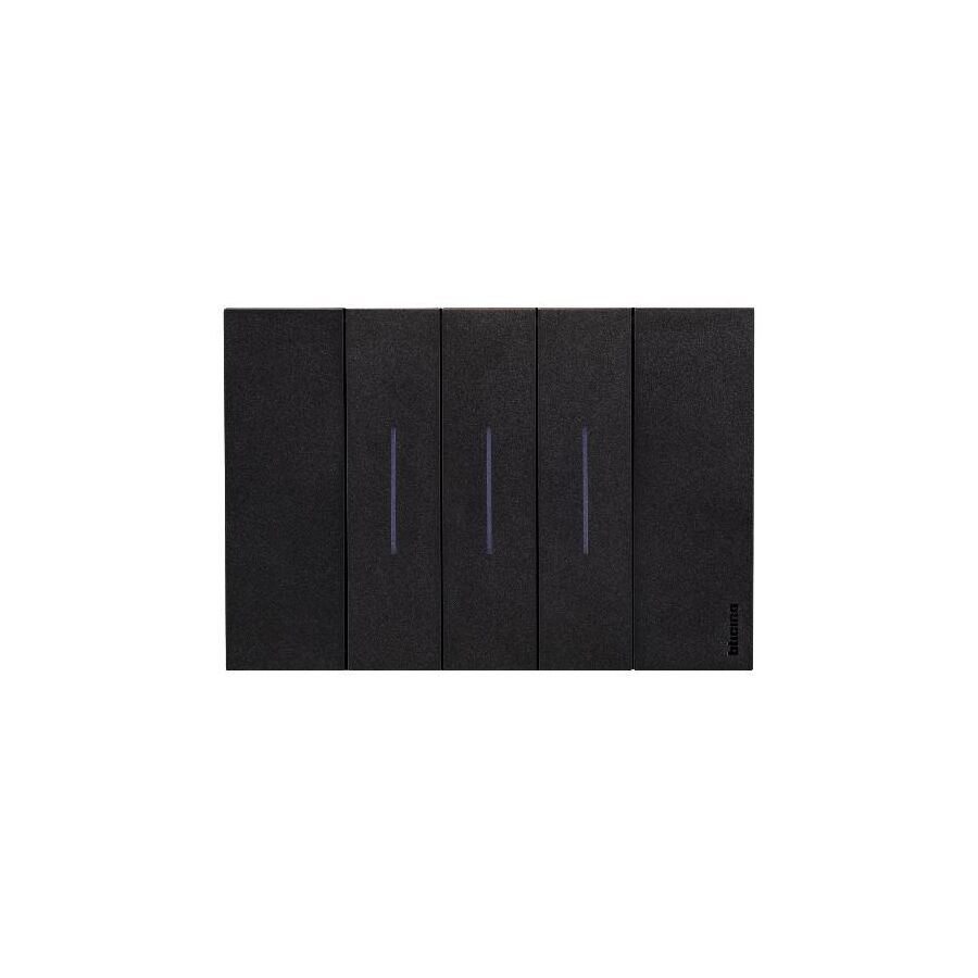
In contemporary Australian residential and commercial interiors, lighting is no longer a single, central utility. It is a layered design element that shapes how spaces are used and experienced. Living rooms combine general downlighting with pendants and feature wall lighting. Kitchens separate task lighting from ambient and island illumination. Offices divide presentation zones from circulation and work areas. This zoning approach demands multiple independently controlled circuits, yet architects and clients increasingly expect clean wall lines with minimal visual clutter. The industry standard solution that balances these competing requirements is the 3 gang switch. By consolidating control of three independent electrical loads into a single wall plate, it delivers functional density while preserving aesthetics, provided the installation respects the physical and electrical limits of the system.
The Australian 3 gang switch is defined by its modular grid and plate construction. Rather than being a single moulded unit, it is assembled from three core components: the mounting grid, the individual switch mechanisms, and the fascia plate. This architecture offers flexibility that is essential in modern fit-outs.
A 3 gang plate does not need to contain three identical switches. It can house a combination of one-way, two-way, intermediate, or dimmer mechanisms depending on circuit logic. This is particularly valuable in open-plan areas where one switch may control a two-way hallway circuit, another a pendant light, and the third an outdoor zone. The rigidity of the grid is critical. With three mechanisms installed side by side, the grid must resist twisting when fixed to uneven plasterboard or rendered masonry. Systems supplied by Schnap Electric Products are engineered with reinforced screw points and stable polymers that maintain alignment, ensuring the fascia clips on cleanly and remains flush over time.
The most significant technical challenge with a 3 gang switch is wiring congestion. Three actives, three switched actives, earth conductors, and often looping neutrals must all be accommodated within a standard mounting block. This concentration of copper is known as box fill, and it directly affects safety and reliability.
AS/NZS 3000 requires that conductors are not damaged by mechanical pressure and that terminations are not strained. In practice, this means disciplined cable preparation. Sheaths should be stripped back only to the entry point, conductors folded neatly rather than compressed, and excess length avoided. Active looping is a common pressure point. Bridging the supply across three mechanisms using twisted conductors creates bulk and stiffness. Professional installers instead use dedicated looping terminals or compact connectors that distribute the active cleanly without creating a solid mass behind the switches. Adequate wall box depth is also essential. Shallow cavities force cables hard against the rear of the mechanisms, increasing heat and long-term failure risk.
A 3 gang switch is rarely three simple one-way switches. One or more gangs are often part of multi-way switching arrangements. Hallways, stairwells, and large rooms frequently require two-way or intermediate switching, adding complexity to the termination process.
Each mechanism type has distinct terminals. One-way switches use active and switched active only. Two-way switches introduce common and strapper terminals. Intermediate switches cross strappers to allow control from three or more locations. In a 3 gang assembly, placing the correct mechanism in the correct grid position is critical. Clear terminal markings and consistent orientation reduce wiring errors and simplify fault-finding. Professional-grade mechanisms provide generous terminal access and clear labelling, which is particularly valuable when multiple circuit types are combined behind one fascia.
Modern lighting loads impose stresses that older switch designs were never intended to handle. LED drivers generate high inrush currents at the moment of switch-on. While the steady-state current may be low, the instantaneous surge can be dozens of times higher.
When a 3 gang switch controls three LED circuits simultaneously, the combined inrush can be significant. Inferior mechanisms with thin contact materials are prone to contact welding, where the contacts fuse together and the switch fails in the on position. High-quality mechanisms mitigate this risk through rapid snap-action springs and silver-nickel contact alloys that resist arc erosion. Specifying mechanisms rated for LED or inductive loads is essential in any multi-gang configuration, particularly in kitchens, garages, and commercial spaces with high fitting counts.
Although each switch generates only minimal heat, three mechanisms operating side by side create a localised thermal environment. This is especially relevant if one or more gangs are dimmers or electronic controls.
Heat dissipation depends on airflow behind the plate and the thermal properties of the materials used. Crowded cables, poor dressing, or installation against insulated walls can trap heat. Best practice avoids combining multiple dimmers in a single 3 gang plate and instead uses push-button controls linked to remote dimming modules. Where electronic devices are unavoidable, derating guidelines must be followed to ensure components operate within their thermal limits.
The physical orientation of a 3 gang switch influences usability. Vertical layouts are common near doorways, while horizontal layouts are often specified above benches or splashbacks to align with joinery and tile lines.
Professional systems allow mechanisms to be rotated within the grid so that switch operation remains intuitive regardless of plate orientation. Consistent tactile feedback, predictable switch direction, and logical grouping all contribute to a positive user experience. Poor layout leads to trial-and-error switching, undermining the purpose of zoned control.
With three apertures cut into a single fascia, the remaining material between mechanisms is relatively thin. Low-grade plastics can crack, discolour, or deform under repeated use or UV exposure.
High-quality 3 gang switches are moulded from UV-stabilised polycarbonate or ASA, materials chosen for impact resistance and colour stability. This ensures the switch maintains its appearance and protective function throughout the life of the fit-out, even in sunlit rooms or high-traffic commercial environments.
Every switch installed in Australia must comply with AS/NZS 3133 and carry the Regulatory Compliance Mark. Non-compliant accessories present a serious safety risk and expose installers and owners to liability.
Specialist electrical wholesaler play a key role in maintaining compliance. They supply certified components, compatible mounting accessories, and technical guidance on derating and configuration. Access to a complete, tested system reduces installation risk and ensures consistent performance across the project.
The 3 gang switch is a cornerstone of modern Australian lighting design. It enables sophisticated zoning while preserving clean architectural lines. Achieving this balance requires more than simply fitting three switches behind one plate. Proper cable management, correct mechanism selection, attention to LED inrush behaviour, and use of robust modular systems are all essential. By applying these principles and specifying proven hardware from manufacturers such as Schnap Electric Products, industry professionals can deliver installations that are safe, compliant, and intuitive to use. In the science of lighting control, thoughtful consolidation defines quality.
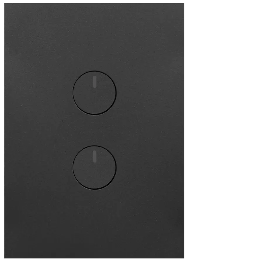
In contemporary Australian homes and light-commercial spaces, electrical design has moved well beyond the era of a single light controlled by a single switch. Open-plan layouts, layered lighting schemes, ceiling fans with integrated light kits, and outdoor feature lighting all demand more nuanced control. A single gang switch often falls short in these scenarios, forcing designers to add extra wall plates that clutter finishes and disrupt architectural flow. The industry standard solution for managing two independent electrical loads from one wall position is the 2 gang switch. By integrating two discrete switch mechanisms into a single plate footprint, this device delivers functional density without sacrificing ergonomics or compliance, making it one of the most widely specified switching formats in Australian construction.
The defining advantage of Australian switching hardware lies in the grid and plate architecture. A 2 gang switch is not a fixed unit but a configurable assembly composed of a mounting grid, two independent switch mechanisms, and a fascia plate. This modularity provides exceptional flexibility during both initial installation and future upgrades.
Using the Schnap Electric Products modular system, a 2 gang grid can house any compatible combination of mechanisms. Typical residential configurations include two 10 amp lighting switches, but the same grid can support a dimmer paired with a standard switch, a fan controller next to a light switch, or a momentary mechanism for automation alongside a mechanical isolator. This adaptability allows electricians to tailor the control interface precisely to the function of the space without enlarging wall penetrations or altering the visual language of the fit-out.
Although the external footprint of a 2 gang switch is identical to a single gang plate, the internal wiring complexity is significantly higher. Two active feeds, two switched actives, earth conductors, and often looping neutrals must all be accommodated within a standard mounting block.
AS/NZS 3000 places clear responsibility on the installer to ensure that insulation is not damaged by overcrowding and that conductors are not subjected to mechanical stress. Effective cable dressing is essential. Outer sheaths should be stripped back only to the cable entry point, conductors should be folded neatly rather than compressed, and excess copper should never be forced behind the mechanisms. High-quality switch mechanisms incorporate dedicated looping terminals that allow the active feed to be bridged cleanly between both switches without creating bulky wire joints. This disciplined approach reduces resistance, minimises heat build-up, and ensures the plate can be refitted flush to the wall.
One of the most common technical reasons for specifying a 2 gang switch is two-way switching. Hallways, staircases, and large living spaces often require a lighting circuit to be controlled from two locations. In these scenarios, one gang of the switch is dedicated to the two-way circuit, while the second gang may control an unrelated load such as an external light or exhaust fan.
Correct termination of the common and strapper conductors is critical. Professional mechanisms clearly identify common and traveller terminals, reducing the risk of mis-wiring. Poorly marked or generic mechanisms increase the likelihood of cross-connection, which can result in short circuits or non-functional switching. In a compliant installation, each mechanism operates independently, even when housed within the same grid, preserving both safety and functionality.
The widespread adoption of LED lighting has fundamentally altered the electrical stresses experienced by switching hardware. LED drivers are highly capacitive and can draw extremely high inrush currents at the moment of switch-on. When a 2 gang switch controls two LED circuits simultaneously, the cumulative surge can be substantial.
Switch mechanisms must therefore be rated for inductive or electronic loads rather than purely resistive ones. Mechanisms with silver-nickel contacts, strong spring pressure, and rapid break action are essential to prevent contact welding. Specifying LED-compatible mechanisms is particularly important in kitchens, garages, and workshops where higher wattage LED fittings are common. Failure to consider inrush behaviour is one of the leading causes of premature switch failure in modern installations.
A 2 gang switch may be mounted vertically or horizontally depending on architectural intent. Vertical orientation is common near doorways, while horizontal mounting is frequently used above kitchen splashbacks or bathroom vanities to align with tile layouts and joinery lines.
Professional systems allow the switch mechanisms to be rotated within the grid so that rocker orientation remains intuitive. Regardless of plate orientation, the user expects consistent tactile logic. Ensuring that the switches operate in the conventional direction avoids confusion and improves the overall user experience. This level of detail is often overlooked in low-cost products but is a hallmark of professional electrical design.
With two mechanisms housed closely together, the fascia plate of a 2 gang switch has thinner structural sections than a single gang plate. Inferior plastics can flex, crack, or discolour over time, particularly in sunlit Australian interiors.
High-quality plates are manufactured from UV-stabilised polycarbonate or ASA, materials chosen for their impact resistance and long-term colour stability. These materials ensure that the switch remains visually consistent with surrounding finishes while maintaining adequate protection against dust and incidental moisture. Durability at this level is not just cosmetic; cracked or degraded plates compromise electrical safety and must be replaced.
Every 2 gang switch installed in Australia must carry the Regulatory Compliance Mark and meet the requirements of AS/NZS 3133 and AS/NZS 3000. Non-compliant products are illegal to install and expose contractors and property owners to liability.
Compliance extends beyond the switch itself. Mounting blocks, grids, and accessories must also meet fire and insulation standards. Sourcing complete systems from reputable electrical wholesaler ensures that all components are compatible and certified for Australian conditions.
The electrical accessory market contains a wide range of products with varying levels of quality and compliance. Specialist electrical wholesalers act as critical quality filters, supplying switchgear that has been tested for endurance, thermal performance, and mechanical integrity.
These suppliers also provide guidance on derating requirements when mechanisms are installed side by side, particularly where dimmers or electronic controllers are involved. Access to proper technical data ensures that the final installation performs reliably over its full service life.
The 2 gang switch is the cornerstone of functional lighting control in Australian homes and commercial spaces. It delivers flexibility, reduces wall clutter, and supports modern zoning concepts when specified and installed correctly. By understanding wiring density, two-way switching logic, LED inrush behaviour, and the importance of modular grid systems, and by using proven hardware from manufacturers such as Schnap Electric Products, industry professionals can achieve installations that are safe, compliant, and intuitive to use. In electrical design, effective control begins with thoughtful consolidation.
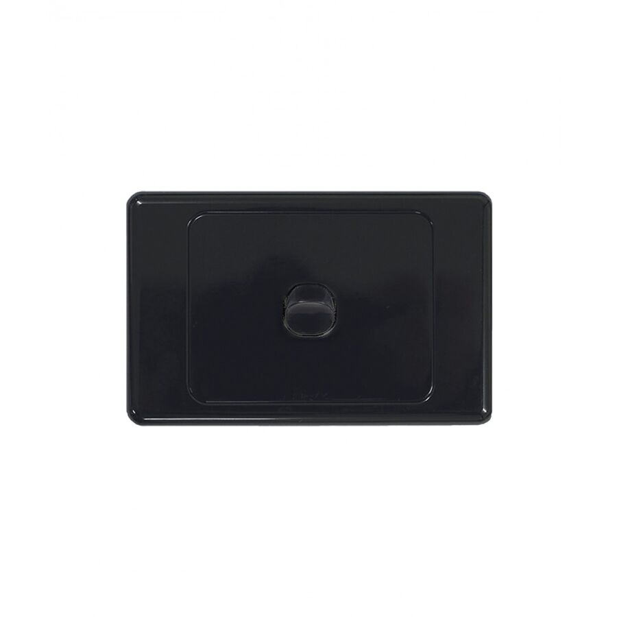
Across the full spectrum of Australian electrical infrastructure, from coastal apartments on the Gold Coast to remote mining dongas in the Pilbara, one component remains universally relied upon. The single gang switch is the fundamental interface between the occupant and the electrical circuit. While smart automation and app-based control systems continue to evolve, the mechanical wall switch remains the most dependable method of isolating a circuit. Its simplicity is deceptive. A compliant single gang switch is a carefully engineered electromechanical device designed to interrupt current safely, repeatedly, and predictably over decades of service while meeting the strict requirements of AS/NZS 3000.
The defining feature of Australian switching hardware is the modular grid and plate philosophy. Unlike monolithic switch assemblies used in other regions, the local standard separates the switch into three distinct elements. These are the mounting grid, the switch mechanism, and the fascia plate. This approach offers both technical and practical advantages.
If a mechanism fails due to wear or contact damage, it can be replaced without disturbing the fascia or mounting grid. This reduces maintenance costs and avoids damage to wall finishes. The modular system also allows a single gang position to host a variety of functions. A standard 10 amp lighting mechanism can be replaced with a higher-rated load isolator, a bell press, or a momentary input for automation systems. The Schnap Electric Products modular ecosystem is designed to support this flexibility while maintaining consistent aesthetics across residential, commercial, and industrial environments.
At the heart of the single gang switch is the mechanism. When a user moves the rocker or toggle to the off position, internal contacts separate and interrupt the flow of current. During this separation, electrical energy attempts to bridge the gap, creating an arc. This arc is extremely hot and, if not controlled, will erode or weld the contacts together.
Professional switch mechanisms are engineered with quick-make, quick-break spring systems. This ensures the contacts separate rapidly regardless of how slowly the user operates the switch. Rapid separation collapses the arc almost instantly. Contact materials are equally critical. High-quality mechanisms use silver-nickel alloy contacts. Silver offers excellent conductivity, while nickel provides hardness and resistance to arc erosion. This combination is essential for handling modern electrical loads, particularly LED lighting circuits that generate very high inrush currents at switch-on.
Modern lighting has changed the electrical behaviour seen by a single gang switch. LED drivers can draw surge currents many times higher than their normal operating current during the first milliseconds of energisation. A switch that is rated only for resistive loads may fail prematurely when subjected to repeated LED inrush events.
For this reason, professional-grade single gang switches are designed with enhanced contact geometry and material composition. These features allow them to withstand repeated inrush cycles without contact welding or degradation. Selecting a switch that is explicitly suitable for LED loads is no longer optional in Australian installations. It is a baseline requirement for reliability.
While the standard single gang plate suits most installations, architectural constraints often require alternative formats. One of the most common is the architrave switch. This narrower profile is designed for mounting on door frames or narrow wall sections where a full-width plate would be intrusive or impractical.
Despite its reduced size, the architrave single gang switch must meet the same electrical and safety standards as a standard plate. Adequate mounting depth, proper earthing, and compliant cable termination are still required. Purpose-designed mounting blocks ensure that the reduced footprint does not compromise wiring bend radius or insulation integrity. When specified correctly, architrave switches provide a clean solution without sacrificing safety or durability.
In many Australian installations, the loop-at-switch method is used. In this configuration, the switch point also acts as a junction for active, neutral, and earth conductors. The switch mechanism must therefore provide a safe and reliable means of looping conductors without placing stress on the switching contacts.
Professional mechanisms incorporate dedicated loop terminals that are electrically isolated from the switching function. These terminals allow multiple conductors to be joined securely while maintaining proper segregation from live switching components. High-quality tunnel terminals with deep conductor entry points and combination head screws provide gas-tight connections that resist loosening due to thermal cycling.
The electrical performance of a switch is only one aspect of its service life. The fascia and grid are exposed to physical impact, cleaning chemicals, and ultraviolet radiation. In Australia, UV exposure is a major factor in material degradation.
Inferior plastics will yellow, become brittle, and eventually crack. This is both an aesthetic and a safety issue. Cracked plates can expose live parts and compromise ingress protection. Professional single gang switches are manufactured from UV-stabilised polycarbonate or ASA. These materials maintain colour stability, impact resistance, and structural integrity over many years of use.
Every single gang switch installed in Australia must comply with relevant standards, including AS/NZS 3133 and AS/NZS 3000. The presence of the Regulatory Compliance Mark is mandatory. Products without certification are illegal to install and expose installers and asset owners to significant liability.
Compliance extends beyond the mechanism itself. Mounting grids, wall boxes, and accessories must all meet applicable fire, mechanical, and insulation requirements. Using a complete, certified system ensures compatibility and simplifies compliance verification.
The proliferation of non-compliant electrical accessories through online marketplaces has increased the risk of unsafe installations. Certified electrical wholesalers play a critical role in maintaining industry standards. They act as technical gatekeepers, ensuring that products meet Australian requirements and are suitable for local conditions.
Specialist suppliers also provide access to compatible accessories such as fire-rated wall boxes, plaster brackets, and alternative mechanisms. This system-level approach reduces installation risk and ensures long-term serviceability.
The single gang switch remains the most important control point in the electrical installation. Its role in circuit isolation, user safety, and daily operation cannot be overstated. Although it appears simple, it embodies advanced material science, precise mechanical design, and strict regulatory compliance. By understanding arc control, load behaviour, modular design, and proper installation practices, and by using proven systems from manufacturers such as Schnap Electric Products, Australian professionals can ensure that this fundamental component delivers reliable performance for decades. In electrical design, the smallest interface often carries the greatest responsibility.
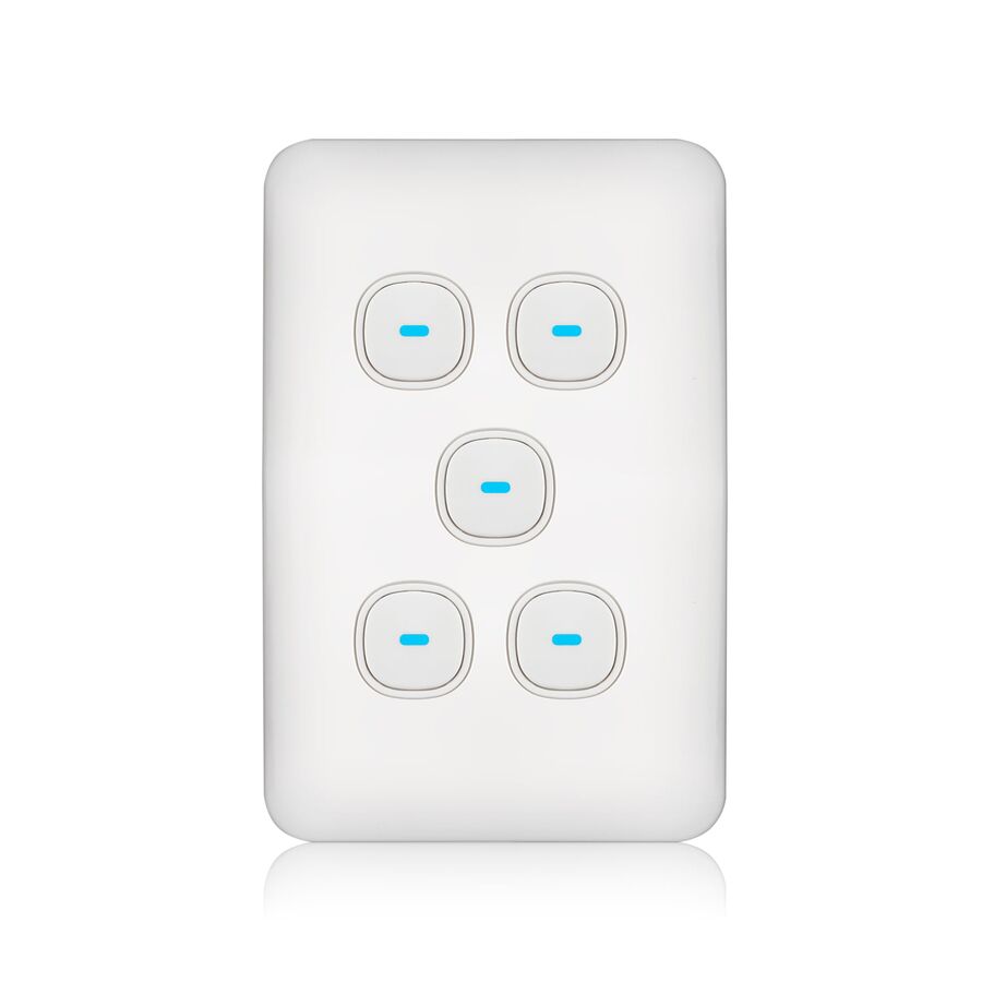
In modern Australian commercial projects and high-end residential developments, electrical control design has shifted toward higher density and greater precision. Open-plan offices, luxury apartments, and mixed-use spaces often require multiple lighting zones, ventilation circuits, and auxiliary loads to be managed from a single wall location. Installing multiple individual switch plates is visually cluttered, inefficient, and inconsistent with contemporary architectural standards.
The 5 gang switch has emerged as the practical upper limit for control density within a standard Australian wall footprint. It delivers five independent switching functions in one consolidated interface. Achieving this level of density safely requires more than simply fitting extra mechanisms into a plate. It demands careful attention to grid strength, cable volume, thermal behaviour, and user ergonomics to ensure compliance with AS/NZS 3000 and long-term operational reliability.
A standard Australian grid plate has finite dimensions. Fitting five switch apertures into this space leaves minimal structural material between mechanisms. Inferior grid plates manufactured from low-grade plastics can flex during installation or deform over time as switches are repeatedly actuated.
A professional 5 gang grid must be manufactured from high-tensile polycarbonate or reinforced thermoplastic. This rigidity prevents distortion when mounting screws are tightened against uneven plasterboard or rendered surfaces. It also ensures the fascia remains flush and aligned, preserving both appearance and tactile quality.
Grid orientation is equally important. Common layouts include vertical five-in-line arrangements or stepped three-over-two configurations. Each layout places different stress patterns on the grid. Rigid modular systems from Schnap Electric Products are engineered to maintain structural integrity regardless of configuration, ensuring the plate does not bow or crack under load.
The most critical technical challenge in a 5 gang switch installation is conductor volume. Five actives, five switched actives, earth conductors, and looped feeds converge into a confined wall cavity. This high density can exceed safe limits if not managed correctly.
Poor box fill leads to compressed insulation, strained terminals, and elevated temperatures. To avoid this, installers must adopt disciplined cable management practices. Cable sheaths should be stripped back precisely to the wall box entry point to maximise usable space. Conductors should be folded and dressed in consistent layers rather than compressed into a tight mass.
Compact lever connectors or dedicated looping terminals are essential for managing common active feeds. Twisting multiple actives together creates bulky joints that push against the rear of the mechanisms and prevent the plate from seating properly. Deep mounting blocks or fire-rated wall boxes are often required to accommodate the cable volume safely.
A 5 gang switch panel concentrates electrical connections into a single location, increasing thermal load within the wall cavity. Each contact generates heat under load. When multiple circuits are energised simultaneously, cumulative heat rise must be considered.
This becomes especially important with LED lighting. Modern LED drivers draw high inrush currents at switch-on. Five LED circuits energised at once can create a substantial surge that stresses contacts and accelerates wear. Switch mechanisms must be rated for inductive loads and LED compatibility, not just resistive current.
Using inferior mechanisms in high-density plates can lead to contact welding or premature failure. Professional designs specify switches with robust silver-nickel alloy contacts and appropriate motor or LED ratings. These materials resist arcing and maintain low contact resistance over thousands of cycles.
Integrating dimmers into a 5 gang plate introduces additional complexity. Multiple dimmers in close proximity require derating due to heat generated by electronic components. In many cases, separating dimming functions from mechanical switching or using low-voltage control inputs linked to remote dimming modules is the safer and more reliable approach.
With five identical switches on a single plate, poor layout quickly leads to user frustration. A well-designed 5 gang switch should be intuitive, allowing users to identify circuits instantly without trial and error.
Logical grouping is essential. Lighting circuits should be arranged to reflect the physical layout of the space. For example, switches on the left side of the plate should control fixtures on the left side of the room. Consistency across rooms and floors improves usability and reduces confusion.
Clear identification further enhances the human-machine interface. Options include engraved fascias, labelled mechanism caps, or subtle iconography. These features are not cosmetic luxuries. They are functional requirements in commercial environments where unfamiliar occupants may need to operate lighting quickly and confidently.
In a 5 gang plate, the strips of material between switch apertures are narrow. Low-quality plastics in these areas are prone to cracking after repeated use. Cracks are not just unsightly. They compromise insulation integrity and expose live parts.
High-quality plates use UV-stabilised polycarbonate or similar materials designed for Australian conditions. These materials resist yellowing, chemical exposure from cleaning products, and long-term embrittlement. Maintaining mechanical integrity over the life of the installation is essential for ongoing compliance and safety.
All components used in a 5 gang switch assembly must comply with relevant Australian Standards, including AS/NZS 3000 and AS/NZS 3133. Custom or imported plates that lack certification may not meet dielectric strength, spacing, or mechanical retention requirements.
Compliance extends beyond the switch itself. Mounting boxes, grids, and accessories must all be suitable for high-density installations. Using a unified modular system ensures dimensional compatibility and simplifies maintenance or future upgrades.
Given the tight tolerances and high stresses involved, sourcing 5 gang switch components from reputable electrical wholesaler is essential. Specialist suppliers provide access to certified grids, deep wall boxes, compatible mechanisms, and technical guidance.
This approach reduces installation risk and ensures that replacement parts remain available over the life of the building. It also supports consistent quality across large projects where dozens or hundreds of high-density switch plates may be installed.
The 5 gang switch represents the practical limit of mechanical switching density within a standard Australian wall footprint. When designed and installed correctly, it delivers powerful, elegant control without visual clutter. Achieving this outcome requires disciplined cable management, careful thermal planning, robust materials, and intuitive layout logic. By using rigid modular systems and high-quality mechanisms from manufacturers such as Schnap Electric Products, Australian professionals can deliver safe, compliant, and durable control interfaces. In high-density switching, precision is not optional. It is the foundation of performance.
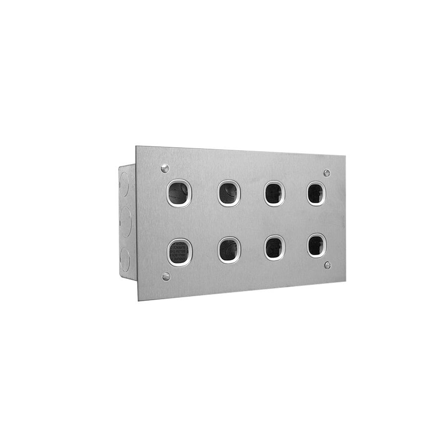
In modern Australian commercial buildings and high-end residential developments, electrical control has evolved far beyond simple on-off switching. Architectural lighting schemes now integrate layered illumination, feature lighting, outdoor zones, exhaust systems, motorised blinds, and auxiliary power circuits. Consolidating these functions into a usable, elegant interface is no longer optional. It is a core design requirement. The traditional approach of scattering multiple single-gang plates along a wall is visually cluttered, inefficient to install, and confusing for occupants.
The industry-accepted solution is the 8 gang switch panel. This format consolidates up to eight independent circuits into a single, coordinated control surface. When properly engineered, it provides clarity, reliability, and long-term durability. When poorly planned, it becomes a thermal risk, a wiring nightmare, and a maintenance liability. The performance of an 8 gang panel depends not only on the visible fascia but on the structural grid, cable management strategy, and contact design hidden behind the wall.
An 8 gang switch panel concentrates mechanical load into a single plate. Each switch is operated multiple times per day, often with varying force. Inferior grids manufactured from thin thermoplastic flex under load. Over time this leads to loose mechanisms, uneven fascias, and inconsistent tactile response.
Professional panels utilise reinforced metal grids or high-strength polycarbonate yokes designed to resist torsional stress. This rigidity ensures the switches remain aligned, the fascia sits flush, and the switching action remains crisp throughout the life of the installation. In commercial environments with uneven masonry or rendered walls, grid stiffness becomes even more critical. A rigid grid compensates for substrate irregularities and prevents long-term distortion.
Systems built around modular platforms from Schnap Electric Products are designed specifically to address these mechanical stresses. Their grid systems are engineered to support high-density layouts without flex, ensuring consistent performance across all eight mechanisms.
The most technically demanding aspect of installing an 8 gang switch panel is managing conductor volume. Eight switched actives, multiple looped actives, neutrals, and earth conductors converge into a confined cavity. Australian wiring rules impose strict limits on conductor crowding to prevent insulation damage and heat accumulation.
Standard wall brackets are rarely sufficient. Deep wall boxes or dedicated fire-rated enclosures are often required to maintain correct bend radius and avoid compressing conductors against the rear of the switch mechanisms. Poor box-fill practices increase the risk of damaged insulation, stressed terminals, and overheating under load.
Professional installers reduce congestion by stripping cable sheaths precisely at the entry point and consolidating common feeds using compact lever connectors. This approach reduces copper bulk and improves airflow behind the plate. Proper dressing also simplifies future maintenance, allowing individual circuits to be identified and isolated without disturbing adjacent terminations.
An 8 gang panel represents a concentration of switching devices and therefore a concentration of heat. While standard mechanical switches generate minimal heat, the risk escalates when dimmers, electronic controls, or inductive loads are involved.
Triac-based dimmers are particularly sensitive to thermal buildup. Installing multiple dimmers in a single plate requires derating calculations to prevent component failure. For this reason, professional designs typically separate dimming functions from high-density mechanical switching or use low-voltage control interfaces connected to remote dimming modules.
Even with standard switches, modern LED lighting introduces high inrush currents. When multiple LED circuits energise simultaneously, contact stress can be significant. Switch mechanisms must be specified with contact materials capable of handling repeated inrush events without welding or pitting. Silver-nickel alloy contacts are preferred for their durability and arc resistance.
An 8 gang panel presents a user interface challenge. Eight identical switches without clear identification create confusion and undermine the purpose of consolidation. Effective human-machine interface design is essential.
Professional installations use etched fascias, engraved legends, or icon-based identification to communicate function instantly. Logical grouping improves usability. For example, lighting circuits may occupy the upper row while services such as exhaust fans or outdoor lighting are grouped below. Consistency across the building is critical so users can intuitively understand control layouts.
In advanced projects, the panel may act as a low-voltage control interface for automation systems rather than directly switching 230 V loads. Even in these cases, clear labelling remains essential to ensure intuitive operation during both normal use and emergency scenarios.
Switch panels are high-touch surfaces exposed to frequent cleaning, ultraviolet light, and occasional impact. Inferior plastics discolour, crack, or become brittle over time, detracting from the architectural finish.
High-quality 8 gang panels are manufactured from UV-stabilised polymers such as ASA or from anodised aluminium. These materials resist yellowing, chemical attack, and surface wear. In coastal or industrial environments, internal components must also resist corrosion to ensure long-term electrical reliability.
The choice of materials is not purely aesthetic. Surface degradation can compromise switch alignment and insulation integrity, creating safety risks long after installation.
All components used in an 8 gang switch panel must comply with Australian standards, including AS/NZS 3133 and AS/NZS 3000. Custom plates or imported assemblies that lack certification introduce significant liability for asset owners and contractors.
Proper compliance extends beyond the visible plate. Mounting boxes, grids, and mechanisms must be rated for the intended configuration and environment. Using approved modular systems ensures that spacing, creepage distances, and mechanical retention meet regulatory requirements.
Given the complexity of high-density switching, procurement through specialist electrical wholesaler is essential. These suppliers provide access to compatible grids, deep wall boxes, joiner plates, and correctly rated mechanisms. They also offer technical guidance on layout configuration and load management.
Working within a unified ecosystem reduces compatibility issues and ensures that replacement components remain available throughout the building’s lifecycle. This approach simplifies maintenance and future upgrades while maintaining compliance.
The 8 gang switch panel represents the highest level of traditional hard-wired circuit consolidation. It delivers clarity, efficiency, and architectural refinement when engineered correctly. By respecting cable density limits, managing thermal loads, implementing logical labelling, and utilising robust modular systems from manufacturers such as Schnap Electric Products, Australian professionals can deliver control interfaces that are both elegant and dependable. In modern building services, consolidation is not merely about saving space. It is about creating control systems that remain safe, intuitive, and reliable for decades.
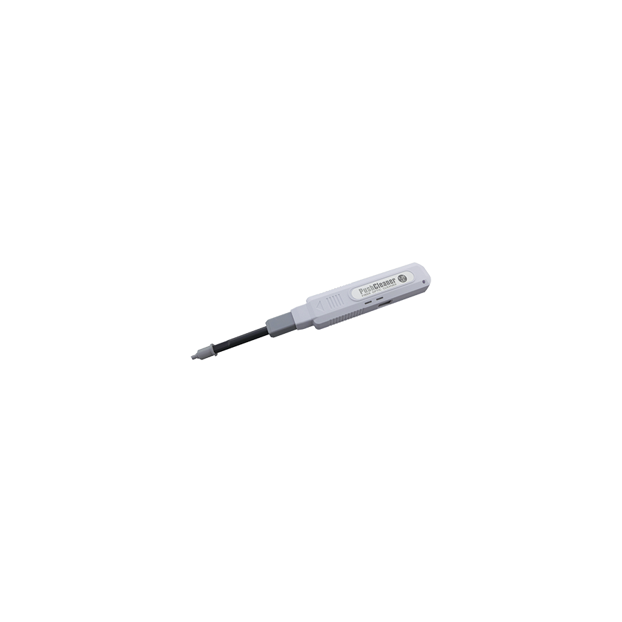
In the precision-engineered landscape of Australian telecommunications, data centres, and enterprise networks, fibre optic performance is governed by tolerances measured in micrometres. As network speeds accelerate toward 400G and 800G architectures, the optical link budget becomes unforgiving. In this environment, the most common cause of degraded performance is not fibre breakage or transceiver failure, but contamination at the connector end-face. A single dust particle, invisible to the naked eye and measuring less than one micrometre, can obstruct or distort light transmission through a Single Mode fibre core that is only nine micrometres wide. The industry-standard solution for maintaining connector hygiene without introducing solvents or lint is the fibre optic cleaner pen. This compact mechanical tool is engineered to remove oils, dust, and saline residue from ferrule end-faces using a calibrated dry-cleaning action that aligns with IEC 61300-3-35 inspection and acceptance criteria.
Fibre optic connectors rely on precise physical contact between polished ceramic ferrules. When two connectors are mated inside an adapter, spring pressure forces the glass end-faces together to minimise signal loss. Any foreign material at this interface disrupts the optical path. The first consequence is increased insertion loss, where light is absorbed or scattered before reaching the receiver. The second and more damaging effect is optical return loss, also known as back-reflection. Contaminants introduce air gaps or refractive index mismatches, causing a portion of the transmitted light to reflect back toward the laser source. In modern high-speed systems, this reflected energy destabilises the laser, increases bit error rates, and produces intermittent faults that are difficult to trace. As data rates rise, tolerance for these reflections falls sharply, making cleanliness a fundamental requirement rather than a best practice.
Historically, technicians cleaned fibre connectors using isopropyl alcohol and cotton swabs. While effective in theory, this method introduces multiple risks. Alcohol can leave a residue after evaporation, forming a halo around the fibre core that attracts dust. Cotton swabs shed microscopic fibres that remain trapped on the end-face. Both issues create repeat contamination and inconsistent results. The fibre optic cleaner pen eliminates these variables by using a dry-cleaning mechanism. Inside the pen is a reel of high-density, anti-static microfibre. Each activation advances a fresh section of cleaning fabric while rotating the tip, producing a combined sweeping and lifting motion. This action removes contaminants from the ferrule surface and captures them within the fibre weave, preventing redeposition. The result is a consistent, repeatable cleaning process that does not depend on operator skill or environmental conditions.
The defining feature of the cleaner pen is its click-to-clean logic. When the pen is inserted into a bulkhead adapter or applied directly to a patch lead and pressed, an internal spring mechanism engages. The cleaning strand advances and rotates simultaneously, ensuring that no section of fabric is reused. This controlled movement applies uniform pressure to the ferrule end-face, avoiding scratches or uneven wear. Because the cleaning surface is dry and anti-static, it does not attract airborne particles during or after the process. This makes the tool particularly suitable for high-density racks, field cabinets, and outdoor enclosures where dust control is challenging.
Fibre connectors are differentiated by ferrule diameter, and cleaner pens are designed accordingly. Connectors with 1.25 mm ferrules, such as LC and MU types, dominate modern data centres and NBN installations due to their high-density form factor. These require a pen specifically sized for the smaller ferrule to ensure full contact with the end-face. Connectors with 2.5 mm ferrules, including SC, ST, and FC types, remain common in legacy systems, industrial automation networks, and campus backbones. A professional fibre toolkit must include both cleaner pen sizes to maintain compatibility across mixed infrastructures. Many high-quality pens also feature extendable nozzles, enabling access to recessed adapters and compact patch panels where direct access is restricted.
The effectiveness of a cleaner pen depends on the quality of its cleaning medium and mechanical tolerances. Inferior tools may use abrasive fabric that scratches the ferrule surface, permanently degrading performance. This is where the Schnap Electric Products ecosystem supports network reliability. Alongside fibre patch leads, wall plates, and termination hardware, Schnap Electric Products supplies cleaner pens engineered for non-abrasive performance and static control. The microfibre strands are specified to remove oils, including skin residue from accidental contact, without charging the ferrule surface. This prevents immediate re-contamination and preserves the polished geometry of the connector, extending the service life of fibre assemblies.
In Australia’s carrier-grade and NBN-ready environments, cleaning is governed by a strict inspect-clean-inspect methodology. IEC 61300-3-35 defines acceptable contamination limits by dividing the ferrule end-face into zones, including the core, cladding, adhesive, and contact regions. Contamination within the core zone is unacceptable and requires remediation. Best practice dictates that technicians inspect the connector using a video microscope before cleaning. If contamination is detected, the cleaner pen is applied, typically requiring a single activation. The connector is then re-inspected to confirm compliance. This protocol ensures that cleaning is purposeful rather than excessive, reducing wear on the ferrule. In emergency restoration scenarios where inspection equipment is unavailable, a high-quality cleaner pen provides the most reliable means of restoring service quickly and safely.
Cleaner pens improve not only optical performance but also operational efficiency. They eliminate the need for liquids, drying time, and waste materials. This reduces contamination risk in live environments and speeds up installation and maintenance tasks. In large data centres where hundreds of terminations may be handled in a single session, consistent cleaning reduces troubleshooting time and prevents costly rework. The ability to achieve repeatable results with minimal training also supports workforce scalability, an important consideration as fibre deployment expands across Australia.
The market contains counterfeit or low-quality cleaner pens that jam, shed debris, or fail after limited use. In mission-critical environments, such failures compromise network integrity and increase downtime risk. Professional network installers and facility managers source cleaner pens through specialised electrical wholesaler that verify product authenticity and performance ratings. Reputable suppliers stock tools rated for hundreds of cleaning cycles and compatible with carrier-grade infrastructure. Supporting accessories such as dust caps, mating sleeves, and fibre management hardware complete the contamination control strategy, ensuring that cleanliness is maintained from installation through ongoing operation.
The fibre optic cleaner pen is a small tool with an outsized impact on network performance. By addressing the microscopic causes of insertion loss and back-reflection, it protects the integrity of high-speed optical links. Understanding the physics of light transmission, adhering to IEC inspection standards, and using precision cleaning tools from manufacturers such as Schnap Electric Products allows Australian industry professionals to deliver fibre networks that meet their designed performance. In the world of optics, cleanliness is not optional; it is the foundation of reliable connectivity.
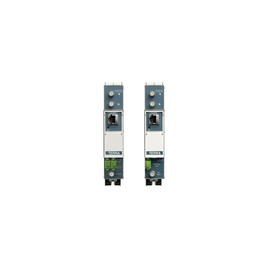
Across Australia’s vast and geographically demanding telecommunications environment, the limitations of copper-based signal distribution are well understood. Coaxial cable, while robust and familiar, suffers from attenuation, noise ingress, and bandwidth ceilings that become unavoidable as distances increase. Whether distributing Foxtel services through a multi-storey residential tower in Melbourne or extending broadband capacity across a Hybrid Fibre-Coaxial network in suburban Sydney, copper inevitably reaches a performance threshold often described as the digital cliff. Beyond this point, signal quality collapses rapidly and remediation becomes impractical. The industry-standard engineering solution is the optical transmitter. This active photonic device converts radio frequency electrical signals into modulated light, allowing those signals to traverse kilometres of single-mode fibre with minimal degradation and exceptional stability.
An optical transmitter functions as the boundary between electrical RF infrastructure and optical distribution. Unlike Ethernet transceivers that operate on binary data, RF optical transmitters must preserve the full analogue waveform of the input signal. This includes analogue television carriers, digital QAM multiplexes, and satellite intermediate frequencies. Any distortion introduced during conversion is amplified downstream and becomes visible to end users as noise, tiling, or service dropouts. As a result, transmitter performance directly determines the quality of the entire downstream network.
At the core of the transmitter is the electro-optical conversion process. The electrical RF signal modulates the intensity of a laser source in a linear manner. This requirement for linearity distinguishes RF optical transmitters from simple digital optics. The industry standard light source is the Distributed Feedback laser. A DFB laser incorporates a diffraction grating within the semiconductor structure, forcing emission at a single, tightly controlled wavelength. This narrow linewidth is critical. It reduces chromatic dispersion in the fibre and ensures that the optical signal faithfully reproduces the RF spectrum without intermodulation distortion.
Poor linearity introduces composite second order and composite triple beat distortion products. These artefacts accumulate across channel line-ups and degrade carrier-to-noise ratios. In practical terms, viewers experience snowy analogue pictures, unstable digital services, or increased bit error rates. High-quality DFB lasers minimise these effects and are therefore mandatory for professional HFC and MATV deployments.
Optical transmitters are typically specified for operation at either 1310 nm or 1550 nm. Each wavelength serves a distinct role in network design. The 1310 nm window aligns with the zero-dispersion point of standard single-mode fibre. Pulse spreading is minimal, making it ideal for short to medium point-to-point links within buildings or campuses. However, fibre attenuation at this wavelength is higher, limiting economic reach.
The 1550 nm window offers the lowest attenuation in silica fibre and is compatible with optical amplification. This makes it the preferred choice for long-haul distribution and large-scale networks. When combined with erbium-doped fibre amplifiers, a single 1550 nm transmitter can serve thousands of endpoints through passive splitting. This capability underpins modern RF over Glass and fibre-based MATV architectures across Australia.
One of the most critical parameters in transmitter configuration is the optical modulation index. OMI defines how deeply the RF signal modulates the laser output. Too little modulation results in a weak optical signal buried in noise. Too much modulation drives the laser into non-linear regions, producing distortion. Maintaining optimal OMI is therefore essential.
Professional optical transmitters incorporate automatic gain control circuits. These systems continuously monitor the RF input level and adjust the laser drive current accordingly. This compensation accounts for upstream fluctuations caused by temperature variation, ageing components, or changes in the coaxial feed. Stable OMI ensures consistent output power and protects downstream receivers from overload or under-drive conditions.
Laser diodes are highly sensitive to temperature. As temperature rises, the emission wavelength shifts and output power changes. In Australia’s climate, where communications rooms may experience elevated temperatures during summer or HVAC failures, unmanaged thermal drift can compromise network integrity.
Commercial-grade optical transmitters integrate thermo-electric coolers to maintain the laser at a constant operating temperature. By actively regulating the laser environment, TEC systems prevent wavelength drift and preserve linearity. This stability is particularly important in wavelength-division multiplexed systems, where channel spacing is tight and crosstalk must be avoided.
An optical transmitter does not operate in isolation. Its performance depends heavily on the quality of the surrounding infrastructure. Clean power, proper fibre management, and mechanical protection are all essential. In Australian installations, technicians frequently integrate supporting components supplied by Schnap Electric Products. Rack-mounted power distribution with surge suppression protects sensitive laser electronics from transient voltage events. Fibre management trays, bend-radius guides, and patch panels ensure that optical fibres leaving the transmitter are not subjected to micro-bending or compression. These physical protections preserve optical power budgets and prevent avoidable insertion loss.
Optical transmitters deployed in Australia must meet strict regulatory and electromagnetic compatibility requirements. Devices lacking proper compliance markings risk interference with other services and may be rejected by network operators. High-quality transmitters are tested for linearity, output stability, and spectral purity before release. These test reports form part of commissioning documentation and provide assurance that the network will perform as designed.
The telecommunications market includes a range of low-cost transmitters that appear attractive on paper but fail under real-world conditions. Common issues include poor thermal management, unstable lasers, and inaccurate AGC circuits. Such shortcomings result in intermittent faults that are difficult and expensive to rectify.
Professional installers source optical transmitters through specialised electrical wholesaler that provide traceability and technical support. These suppliers also stock essential accessories such as optical attenuators, cleaning tools, and test equipment. Proper commissioning includes setting optical output power within receiver tolerance, cleaning connectors, and verifying signal quality across the distribution network.
The optical transmitter is the cornerstone of modern RF distribution in Australia. It enables broadband, television, and satellite services to move beyond the physical limits of copper and into scalable fibre architectures. By understanding the physics of electro-optical conversion, selecting the appropriate wavelength, managing modulation and temperature, and supporting the installation with robust infrastructure from manufacturers such as Schnap Electric Products, industry professionals can build networks that are reliable, compliant, and future-ready. In the science of transmission, light is not merely a medium; it is the enabler of national connectivity.

SCHNAP Electrical Wholesaler - clear, upfront pricing that professional electricians trust

Get what you need in seconds. SCHNAP electrical wholesaler makes ordering quick and simple

Fast delivery anywhere - that's guaranteed. SCHNAP electrical wholesalers ship nationwide with same-day dispatch

Track your order every step of the way. SCHNAP electrical wholesale keeps you updated from click to delivery

SCHNAP is Australia's premier electrical wholesaler and electrical supplies, marketing thousands of quality products from leading brands. Trusted for nearly two decades by licensed electricians, contractors, and engineers, our range covers everything from basic electrical components to complex industrial electrical equipment
Our key categories include: LED lighting, designer switches, commercial switchboards, circuit protection, security systems & CCTV, and smart home automation
All products are certified to Australian standards (AS/NZS), backed by our 30-day, no-questions-asked return policy. Our expert technical team helps you quickly source the right solution for any residential, commercial, or industrial project, with daily dispatch from our Sydney electrical warehouse delivering Australia-wide
SCHNAP offers the most comprehensive electrical product range, with full technical specifications, application details, installation requirements, compliance standards, and warranties — giving professionals total confidence in every purchase


