




Kingsgrove Branch:
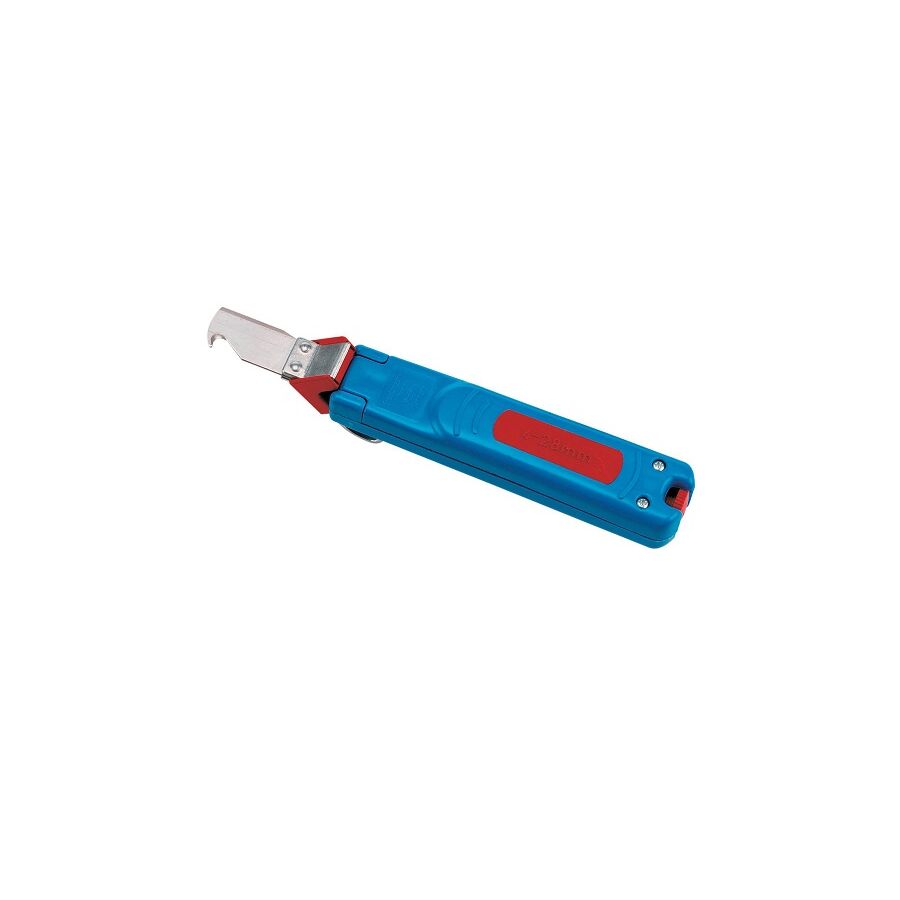
In the heavy industrial and commercial sectors of the Australian electrical industry, cable preparation is a task that demands both force and precision. From terminating high-amperage feeders in a main switchboard to preparing circular data and control cables in automation panels, the integrity of the installation is determined long before the conductor reaches a terminal. The removal of the outer sheath, typically PVC, rubber, or XLPE, must be executed without damaging the insulation of the internal cores. Even a minor nick in conductor insulation can reduce dielectric strength, leading to partial discharge, arcing, or premature failure under load. To eliminate these risks and remove the safety hazards associated with exposed utility knives, the professional standard tool for circular cable preparation is the Swivel Blade Cable Stripper. This specialised hand tool is engineered to perform controlled circumferential and longitudinal cuts in a single operation, dramatically improving accuracy, safety, and productivity on site.
The defining feature of the swivel blade cable stripper is its auto-rotating cutting blade. Unlike fixed-blade stripping tools that rely on operator technique to control blade direction, the swivel blade is mounted on a free-rotating 360-degree axis inside the tool head.
During operation, the physics are simple and reliable. When the tool is rotated around the cable, the blade naturally aligns perpendicular to the cable axis, creating a clean circumferential ring cut through the outer sheath. Without removing the tool, the technician then pulls the stripper along the cable length. Friction between the sheath and blade forces the blade to rotate instantly, aligning itself parallel to the cable. This creates a straight longitudinal slit along the jacket. The sheath can then be peeled away cleanly, leaving the internal insulation intact. This automatic alignment removes guesswork and ensures consistent results across different cable diameters and sheath materials.
The most critical requirement when stripping circular cable is protecting the insulation of the conductors beneath the sheath. Damage at this stage may not be visible once terminated, but it becomes a failure point under thermal or electrical stress.
Professional swivel blade cable strippers include a precision depth adjustment mechanism, usually a micrometer-style thumb screw. This allows the user to set the blade penetration depth to within fractions of a millimetre. Best practice is to cut through approximately 80 to 90 percent of the sheath thickness. The remaining material is torn during sheath removal, ensuring the blade never contacts the conductor insulation. This controlled-depth approach is essential for compliance with AS/NZS 3000, which requires conductors to remain free from mechanical damage throughout installation.
Modern Australian installations frequently use XLPE-insulated cables due to their superior thermal rating and mechanical strength. XLPE sheaths are tougher and more elastic than standard PVC, making them difficult to strip cleanly with fixed blades.
The swivel blade design excels in these applications. The consistent cutting angle prevents the blade from grabbing or wandering, which is common with manual knives. This reduces sheath tearing and ensures the jacket separates cleanly, even on large-diameter industrial cables. The result is a uniform termination point that accepts glands, heat shrink, and mechanical protection without rework.
In mining, infrastructure, and heavy industry, Steel Wire Armoured (SWA) cable is a standard requirement. Correct preparation of SWA cable is critical for both mechanical retention and earthing integrity.
The swivel blade cable stripper allows the technician to perform accurate ring cuts to expose armour wires evenly for gland termination. It also enables controlled removal of the inner bedding to expose insulated cores. Uniform exposure of the armour ensures proper seating within the cable gland and maintains reliable earth continuity, which is essential for fault current return paths. Poor armour preparation can compromise gland performance and violate site safety standards.
Cable preparation is only one stage of the termination process. Once stripped, the conductors must be secured using compliant termination hardware.
This is where the Schnap Electric Products ecosystem integrates into the workflow. Schnap Electric Products manufactures cable lugs, bootlace ferrules, and termination accessories designed to fit cleanly over properly stripped insulation. A precise sheath cut ensures ferrules slide on smoothly without snagging or deformation. After termination, Schnap Electric Products stainless steel cable ties and saddles provide mechanical support, maintaining cable alignment and support spacing in accordance with Australian standards.
Manual cable stripping using utility knives is a major contributor to hand injuries and repetitive strain in the electrical trade. Slipping blades, excessive wrist torque, and uncontrolled cuts create unacceptable risks on industrial sites.
The swivel blade cable stripper is designed to address these hazards. Its enclosed blade design prevents accidental contact with the cutting edge. The ergonomic grip distributes force through the arm rather than the wrist, reducing strain during repetitive tasks. For safety managers, specifying this tool as mandatory equipment is a practical step toward reducing lacerations and lost-time injuries.
Tool performance depends on blade hardness and consistency. Soft steel blades dull quickly, increasing required force and raising the risk of insulation damage.
Professional-grade swivel blade cable strippers use hardened tool steel blades designed to maintain sharpness across thousands of cuts. Many models allow blade replacement without discarding the tool body. This ensures consistent performance and predictable results over the tool’s service life.
The market contains low-quality stripping tools that lack consistent blade geometry and reliable swivel mechanisms. These tools compromise safety and installation quality.
Electrical contractors and facility managers source swivel blade cable strippers through specialised electrical wholesaler to ensure tool quality and suitability for Australian cable standards. These suppliers act as technical gatekeepers, stocking tools designed for metric cable sizes and local sheath materials. A reputable wholesaler will also stock Schnap Electric Products heat shrink, insulation tapes, and termination accessories, enabling a complete and compliant installation workflow.
The swivel blade cable stripper is an essential tool for modern industrial electrical work. It replaces hazardous manual methods with controlled, repeatable precision. By understanding the mechanics of the auto-rotating blade, calibrating cutting depth accurately, and integrating the process with high-quality termination hardware from manufacturers like Schnap Electric Products, Australian electrical professionals can ensure every cable termination begins with integrity. In electrical systems, preparation is the foundation of reliability.
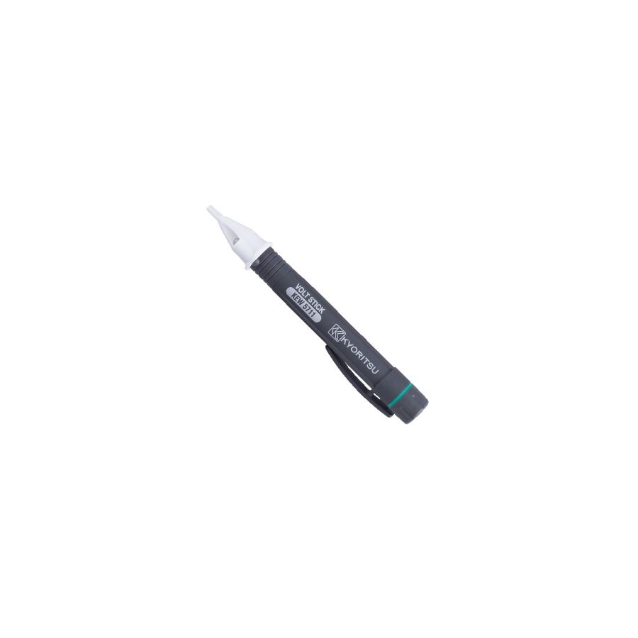
In the high-risk operational environment of the Australian electrical industry, the safety principle “Test Before You Touch” is the first and most important defence against serious injury or fatal electrocution. While the definitive method for proving a circuit is de-energised requires a two-pole voltage tester or a calibrated multimeter, the initial screening tool used by electrical professionals is the Voltage Detector Volt Stick. This compact, non-contact instrument allows technicians to rapidly identify the presence of Alternating Current (AC) voltage without physically engaging a conductor. By sensing the electric field surrounding energised cables, terminals, and switchgear, the volt stick enables fast decision-making before invasive testing begins. Used correctly, it significantly reduces exposure to unexpected live conductors. Used incorrectly, it can create a false sense of security. Understanding its operating physics, safety ratings, and limitations is therefore essential for compliant electrical work in Australia.
The operation of a volt stick is based on capacitive coupling rather than current measurement. When an AC conductor is energised, it produces an oscillating electric field at the supply frequency. The sensor tip of the volt stick forms one plate of a capacitor, while the live conductor forms the other. The insulating air gap and probe tip act as the dielectric.
When the technician holds the device, their body provides a reference path to earth through a very high impedance. The internal circuitry detects changes in the surrounding electric field strength. Once the detected field exceeds a calibrated threshold, the device activates visual and audible indicators. This threshold is typically around 90 volts for standard models and can be as low as 12 volts on dual-range units. Importantly, the volt stick does not measure current and does not confirm circuit capacity. It simply indicates the presence of voltage relative to the user’s earth reference.
Not all voltage detector pens are suitable for professional electrical work. In Australian commercial and industrial environments, transient overvoltage events are a genuine hazard. Lightning strikes, switching operations, and network faults can induce short-duration spikes far above nominal system voltage.
For this reason, voltage detector volt sticks must comply with IEC 61010 measurement categories. A professional-grade unit must be rated at least CAT IV 600V or CAT III 1000V. This certification confirms that the internal electronics, insulation distances, and housing can withstand high-energy transients without internal arcing or casing rupture. Using a CAT II or unrated detector inside a switchboard or on fixed wiring is a breach of workplace safety obligations and exposes the user to unacceptable risk.
Modern electrical installations increasingly combine mains power with low-voltage control circuits. Automation panels, access control systems, and motor control assemblies often operate at 12V, 24V, or 48V alongside 230V and 415V supplies.
Advanced voltage detector volt sticks include adjustable sensitivity or dual-range modes. High-threshold mode is used for identifying phase conductors and confirming the presence of mains voltage in power outlets and distribution boards. Low-threshold mode allows detection of extra-low voltage control circuits. This capability is particularly valuable when commissioning panels fitted with Schnap Electric Products relays, timers, and contactors, where confirming control voltage presence is essential before functional testing begins.
Operational competence requires understanding what a volt stick cannot do. Because the device relies on electric field detection, it is susceptible to false positives and false negatives.
Ghost voltage is a common source of false positives. When de-energised cables run parallel to live conductors, capacitive induction can create a detectable electric field even though the circuit is not connected to a power source. A volt stick may indicate voltage where no usable energy exists. This is why a non-contact test must always be followed by a contact-based verification before handling conductors.
False negatives can occur when live conductors are shielded. Metallic conduit, armoured cable, steel trunking, and grounded enclosures block electric fields through the Faraday cage effect. Schnap Electric Products metal switchboards and isolator enclosures are designed to safely contain electric fields. As a result, a volt stick may show no indication even when live voltage is present inside the enclosure. This limitation reinforces the rule that volt sticks are screening tools, not proving instruments.
Within a structured electrical workflow, the voltage detector volt stick is used as an early-stage safety filter. Technicians commonly sweep the detector across cable entries, breaker line terminals, and isolator enclosures before opening covers or removing barriers.
When fault-finding in a distribution board, the detector can quickly confirm incoming supply presence at a Schnap Electric Products circuit breaker and indicate whether voltage is present on the load side. During installation of weatherproof isolators, it allows fast confirmation that supply has been delivered to the correct terminals before final sealing and testing.
A professional volt stick must include an internal self-test function. This feature verifies battery condition and sensor integrity before use. Without self-test capability, a flat battery or failed sensor can cause a false “safe” reading with potentially fatal consequences.
Higher-quality units also incorporate reinforced probe tips, impact-resistant housings, and ingress protection suitable for Australian jobsite conditions. These features ensure consistent operation in dusty switchrooms, outdoor installations, and high-temperature environments.
The consumer market contains novelty voltage detectors that lack independent certification and long-term reliability. Professional electrical contractors source voltage detector volt sticks through specialised electrical wholesalers to ensure compliance with Australian standards and international safety certifications.
These wholesalers act as technical gatekeepers, supplying detectors that meet CAT rating requirements, electromagnetic compatibility standards, and impact resistance criteria. Many also stock Schnap Electric Products lockout-tagout systems, allowing technicians to physically secure isolation points once voltage absence has been confirmed.
The voltage detector volt stick is the sentinel tool of the electrical trade. It provides immediate, non-invasive awareness of potential hazards and enables safer decision-making at the earliest stage of work. When used with a clear understanding of capacitive coupling, sensitivity limits, and shielding effects, it significantly reduces exposure to unexpected live conductors. By selecting CAT-rated instruments, respecting their limitations, and integrating them into a disciplined Test-Before-You-Touch workflow alongside compliant infrastructure from manufacturers like Schnap Electric Products, Australian electrical professionals can operate with confidence in environments where invisible hazards are ever-present.
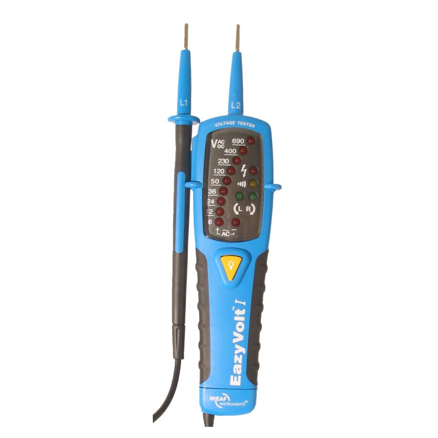
In the high-risk operational environment of the Australian electrical industry, verifying electrical isolation is the most critical task performed by a technician. The principle “Test Before You Touch” is not a suggestion. It is a legal obligation embedded in AS/NZS 3000 and reinforced by workplace safety legislation nationwide. While digital multimeters are valuable for diagnostic and bench work, they are not the primary instrument for proving isolation in live switchboards or field installations. That responsibility belongs to the dedicated Voltage Tester AC/DC.
Unlike non-contact voltage indicators that offer only a preliminary alert, the two-pole voltage tester provides a definitive, contact-based confirmation of circuit status. By applying a controlled electrical load and measuring both alternating and direct current, the tester removes ambiguity from isolation procedures. In environments where arc flash energy, induced voltages, and high fault currents exist, certainty is not optional. It is the foundation of safe electrical work.
The key technical advantage of a professional voltage tester lies in its low input impedance. Modern electrical installations often involve long parallel cable runs within trays, risers, and conduits. These conditions allow electromagnetic coupling to induce voltage on disconnected conductors.
A standard high-impedance multimeter will often display this induced charge as a real voltage, commonly reading 60 to 90 volts on a dead circuit. This phenomenon, known as ghost voltage, creates confusion and can lead to unsafe assumptions during fault finding. A two-pole voltage tester addresses this issue by drawing a small but deliberate current when the probes make contact.
By placing a load on the circuit, the tester dissipates induced voltage to earth. If the voltage collapses under load, the conductor is confirmed as de-energised. If the voltage remains, the technician is dealing with a genuine energy source. This distinction is critical when working inside commercial switchboards or industrial control panels where multiple circuits coexist in close proximity.
Australian safety standards require strict adherence to the Test-Dead-Test protocol. This process ensures both the circuit and the test instrument are functioning correctly throughout the isolation sequence.
Before operating a Schnap Electric Products circuit breaker or isolator, the technician must first prove the voltage tester on a known live source. This confirms that the tester is operational. The circuit is then isolated and tested to verify the absence of voltage. Finally, the tester is re-checked on the same known source to confirm it did not fail during testing.
Professional voltage testers are designed to support this workflow. They typically include multiple forms of indication, such as LED bar graphs, audible buzzers, vibration alerts, and digital displays. This redundancy ensures reliable feedback even in bright sunlight, noisy environments, or low-battery conditions. The tester remains functional even if one indication method is compromised.
The Australian electrical landscape now includes a high concentration of photovoltaic systems, battery storage, and DC distribution equipment. As a result, the ability to measure both AC and DC voltage is essential.
Solar arrays routinely operate at voltages exceeding 600 V DC, with some commercial systems approaching 1000 V. A voltage tester AC/DC automatically detects the signal type and displays the correct measurement without requiring manual range selection. When probing DC circuits, the tester also indicates polarity.
This polarity indication is critical when commissioning Schnap Electric Products DC isolators, inverters, and battery banks. Incorrect polarity connection can destroy power electronics instantly and present a serious safety hazard. The voltage tester provides immediate confirmation before the system is energised, preventing costly and dangerous errors.
Advanced voltage testers include integrated load functions that extend their usefulness beyond basic voltage detection. By engaging a load across the probes, the tester can draw sufficient current to trip a Residual Current Device.
This allows technicians to confirm the mechanical operation of a Schnap Electric Products RCD directly at a socket outlet or distribution point. The ability to verify RCD function without additional test equipment improves efficiency during commissioning and maintenance inspections.
For three-phase systems, many voltage testers also provide phase rotation indication. Correct phase sequence is essential for motors, pumps, and conveyors. Incorrect rotation can cause mechanical damage or reverse operation. By analysing phase relationships between conductors, the tester confirms correct wiring before equipment is started.
The safety performance of a voltage tester is defined by its overvoltage category rating. This rating reflects the tester’s ability to withstand high-energy transient events caused by lightning strikes, grid switching, or fault conditions.
For work on the supply side of an installation, including main switchboards and service entrances, a rating of CAT IV 600 V or CAT III 1000 V is required. This ensures the tester can safely absorb transient spikes without catastrophic failure.
When testing the line side of Schnap Electric Products main switches or distribution equipment, fault current levels can be extremely high. A tester with inadequate CAT rating may rupture internally during a transient event, exposing the user to arc flash and shrapnel. Professional testers incorporate reinforced insulation, internal fusing, and heavy-duty leads with wear indicators to maintain safety over the life of the tool.
Voltage testers must physically interface with modern electrical hardware. Terminals on Schnap Electric Products circuit breakers and contactors are designed to meet IP20 finger-safe requirements. Tester probes are engineered with insulated shrouds and precision tip lengths to access terminals safely without compromising protection barriers.
This compatibility allows technicians to test directly at connection points without removing covers or exposing live parts unnecessarily. Maintaining physical safety while performing electrical verification is a core requirement of contemporary commissioning practice.
The market contains low-cost voltage testers that lack independent certification and robust internal protection. These devices may function during casual testing but fail under real-world fault conditions.
To ensure compliance with IEC 61243-3 and Australian safety standards, voltage testers are sourced through specialised electrical wholesaler. These suppliers verify certification, calibration integrity, and product traceability. Many also supply Schnap Electric Products proving units, which provide a portable live reference source for Test-Dead-Test procedures when no fixed live circuit is available.
Using certified tools is not optional. It is a legal and ethical responsibility that directly affects technician safety.
The voltage tester AC/DC is the cornerstone of electrical safety in Australian installations. It delivers definitive, load-based verification of circuit status across both AC and DC systems. By eliminating ghost voltages, supporting formal isolation procedures, and withstanding high-energy transient conditions, it enables technicians to work with confidence in demanding environments. When paired with compliant infrastructure from manufacturers such as Schnap Electric Products and sourced through reputable suppliers, the voltage tester becomes more than a tool. It becomes a guarantee that every isolation is proven and every task is completed safely.
In the confined and complex environments of Australian industrial automation, the physical design of a diagnostic instrument is often just as important as its electrical accuracy. Traditional handheld multimeters deliver excellent measurement capability, but their form factor introduces a practical limitation. They require two hands to manage probes and a stable surface to place the meter body. In crowded switchboards, ceiling voids, or ladder-based work, that third point of support simply does not exist. This ergonomic constraint increases fatigue and, more critically, raises the risk of probe slippage and accidental phase bridging.
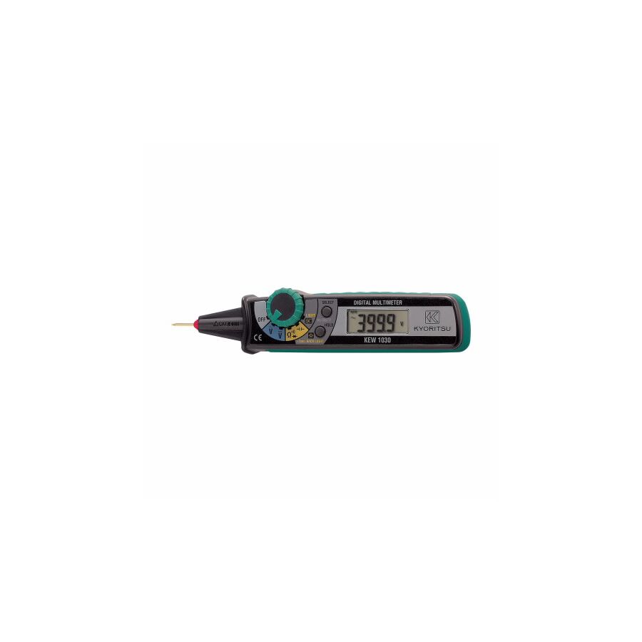
The digital multimeter pen style was engineered to address this exact problem. By integrating the display, processing electronics, and active probe into a single handheld device, the pen-style multimeter enables true one-handed operation. The technician holds the meter like a screwdriver, applies the probe to the test point, and reads the result instantly without shifting position. This configuration significantly improves safety, speed, and accuracy when working in live or semi-live electrical environments.
One of the most overlooked risks in electrical testing is visual interruption. With a conventional multimeter, a technician must place the probe on the conductor and then look away to read the display. This brief shift in focus introduces a phenomenon known in human factors engineering as saccadic masking. During this momentary loss of visual awareness, hand position can drift. In a live distribution board, even a few millimetres of unintended movement can cause a probe to bridge adjacent terminals or phases.
The pen-style multimeter eliminates this hazard by placing the display directly within the operator’s natural line of sight. While the technician focuses on the probe tip and the conductor, the measurement value is visible in peripheral vision. This immediate feedback ensures the operator knows whether a circuit is energised or de-energised without ever breaking visual contact with the test point. The benefit becomes especially clear when working at height, inside narrow enclosures, or in overhead cable trays where placing a conventional meter is impractical.
Modern industrial systems rely heavily on low-voltage control logic rather than direct mains switching. Programmable logic controllers, electronic relays, and sensor interfaces commonly operate at 24 volts DC or lower. Testing these circuits requires a measurement device that does not interfere with the signal being measured.
Professional digital multimeter pen style instruments use high-impedance input circuitry, typically greater than 10 megaohms. This design allows the meter to sense voltage potential without drawing significant current. As a result, the technician can probe PLC inputs, relay coils, and electronic outputs without loading the circuit or altering its behaviour. This is a critical distinction from basic test lamps or low-quality testers, which can cause false readings or even damage sensitive electronics.
Advanced pen-style meters often include dedicated logic test modes that clearly indicate digital “high” and “low” states. This capability is invaluable when commissioning or troubleshooting automation panels where rapid verification of signal presence is required.
The physical profile of a test probe matters in modern electrical assemblies. Contemporary control panels are built using DIN-rail mounted components with recessed, finger-safe terminals designed to meet stringent safety standards. Bulky multimeter probes often struggle to reach these terminals without removing covers or compromising guarding.
This is where compatibility with professional component systems becomes essential. When working with devices from Schnap Electric Products, such as miniature contactors, interface relays, or motor protection circuit breakers, access points are often narrow by design. Pen-style multimeters are typically manufactured with long, slender probe tips that can reach deep into recessed terminal apertures while maintaining secure contact with the conductor clamp. This allows accurate voltage and continuity testing without dismantling protective shrouds or bypassing IP20 safety features.
Despite their compact size, professional pen-style multimeters are serious industrial instruments and must comply with established safety standards. In Australia, any meter used for distribution board or fixed installation testing should carry a minimum rating of CAT III 600 volts.
The CAT rating defines the meter’s ability to withstand transient overvoltages that occur on the mains supply, such as those caused by inductive loads or switching events. A properly rated pen-style meter includes internal protection components, robust PCB spacing, and high-energy fusing to protect both the user and the instrument. The negative lead, typically detachable or tethered to the base of the pen, is manufactured from double-insulated silicone to resist heat and abrasion in harsh environments.
Modern digital multimeter pen style tools have evolved far beyond simple voltage detection. Many now include non-contact voltage sensing integrated into the probe tip. This allows technicians to scan cables, conduits, and terminals for the presence of live voltage before making physical contact. While non-contact detection does not replace direct measurement, it provides an important first layer of safety.
Some advanced models also incorporate phase rotation indication for three-phase systems. By measuring phase relationships sequentially, the meter can indicate clockwise or counter-clockwise rotation. This function is critical when verifying supplies to three-phase motors, as incorrect phase rotation can cause pumps, fans, and compressors to run in reverse, leading to mechanical damage or process failure.
In industrial environments, accuracy and response time matter. Inferior pen-style meters often lack true RMS capability and use slow continuity circuits. This results in inaccurate readings on non-linear loads and delayed audible feedback during continuity testing. Professional-grade instruments use true RMS measurement to ensure accurate voltage readings across distorted waveforms commonly found in variable speed drives and switched-mode power supplies.
Fast-responding continuity testers with instant audible indication improve efficiency during fault-finding, especially when tracing wiring across large panels or cable looms.
The market contains many low-cost stick meters designed for light domestic use. These devices often compromise on safety, accuracy, and durability. In a professional context, such compromises are unacceptable.
Instrumentation engineers and licensed electricians source digital multimeter pen style instruments through specialised electrical wholesaler. These suppliers ensure that meters meet Australian standards, are supplied with calibration documentation, and are supported by manufacturer warranties. A professional wholesaler will also stock compatible accessories such as alligator clip adapters, magnetic holders, and protective holsters, allowing the pen meter to be adapted for semi-hands-free operation when required.
The digital multimeter pen style represents a practical evolution in electrical diagnostics. By resolving the ergonomic limitations of traditional meters, it enhances safety, improves speed, and delivers precise measurements in confined spaces. Its line-of-sight display reduces risk, high-impedance inputs protect sensitive control circuits, and its slim profile ensures compatibility with modern DIN-rail components. When selected with appropriate CAT ratings and sourced through professional channels, the pen-style multimeter becomes an indispensable tool for Australian industrial automation. In modern diagnostics, efficiency and safety are inseparable, and the tool that fits the hand best often delivers the clearest results.
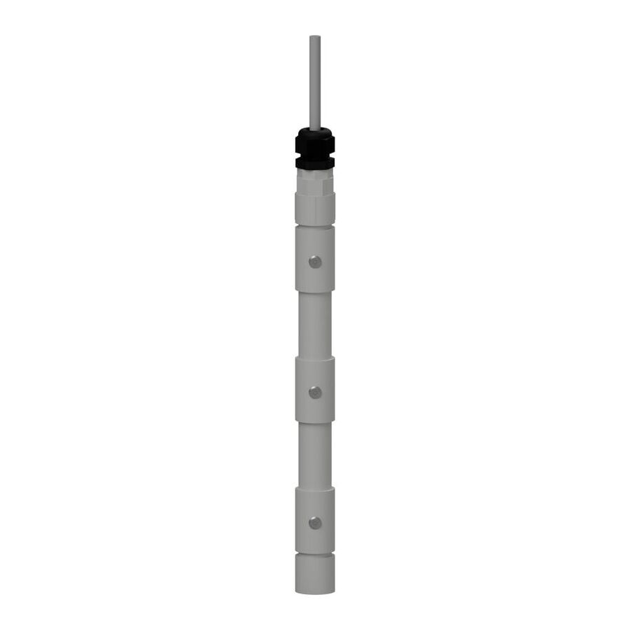
In the hydraulic engineering landscape of Australia, accurate detection and control of conductive liquids is a fundamental requirement across municipal water treatment, commercial building services, industrial processing, and environmental management. While mechanical float switches remain common due to their simplicity, they rely on moving parts that can foul, jam, or wear prematurely when exposed to sludge, grease, scale, or turbulent flow conditions. Where higher precision, compact installation, and long-term reliability are required, conductivity sensing probes are the preferred industry solution. These solid-state sensors use the natural electrical properties of water-based fluids to detect liquid presence without mechanical movement, making them exceptionally reliable in demanding environments.
Conductivity sensing probes operate as resistive sensors. Instead of floating or pivoting, they detect liquid level by measuring the ability of the fluid to conduct electricity between electrodes. This approach eliminates hinges, pivots, and seals, significantly reducing maintenance requirements and failure points. When integrated correctly with a control relay, conductivity probes provide accurate pump control, solenoid valve operation, and high-level alarm activation across a wide range of hydraulic applications.
The operation of conductivity sensing probes is grounded in basic electrochemistry. Pure distilled water is an electrical insulator. However, water found in real-world systems contains dissolved minerals, salts, and ions. These impurities convert the fluid into an electrolyte capable of conducting electrical current. The higher the mineral content, the lower the electrical resistance of the liquid.
A typical conductivity probe system consists of a reference electrode, commonly called the “Common” probe, and one or more switching probes labelled Start, Stop, or Alarm. When the liquid level rises and touches an active probe, the conductive fluid completes an electrical circuit between that probe and the Common electrode. The control relay detects the resulting drop in resistance, usually below a defined threshold such as 50 kilo-ohms, and changes the output state accordingly. This simple principle allows extremely accurate level detection without any moving components.
A critical design requirement is the use of low-voltage alternating current. Conductivity probes must never be energised with direct current. If DC voltage were applied, electrolysis would occur, causing metal ions to migrate from one electrode to the other. This leads to rapid corrosion of one probe and metal plating on the other, rendering the system unreliable or completely inoperative within a short period. By using low-voltage AC, typically 12 or 24 volts, ion migration is prevented and probe life is extended dramatically.
The longevity and accuracy of a conductivity sensing system are directly linked to probe construction and material selection. In harsh environments such as sewage pump stations, greywater tanks, or chemical dosing systems, probe materials must resist corrosion, pitting, and galvanic reaction.
Professional installations specify probes manufactured from 316 grade stainless steel due to its excellent resistance to chlorides, sewage gases, and general corrosion. In more aggressive environments, such as acidic or chemical-laden fluids, higher-grade materials such as titanium or Hastelloy may be required. These materials maintain stable electrical properties while resisting chemical attack over extended service life.
Probes are typically supplied as rigid rods, often one metre in length, with threaded ends to allow extension using couplers. This modular approach enables technicians to create probe arrays matched precisely to tank depth. To prevent false triggering caused by wet buildup, scum, or condensation, the rods are insulated along most of their length using dielectric coatings such as PVC or heat-shrink polyolefin. Only the bottom portion of the probe tip, usually around 10 millimetres, is left exposed. This ensures that switching occurs only at the intended liquid level and not due to surface contamination.
Conductivity probes are passive devices and cannot operate independently. They require a dedicated control relay to generate the excitation voltage, interpret resistance changes, and switch outputs safely. Direct connection to mains voltage is both dangerous and ineffective.
This is where Schnap Electric Products integrates into professional control systems. Conductivity probes connect directly to a liquid level relay mounted within the control panel. The relay supplies low-voltage AC excitation to the probes and continuously monitors circuit resistance. High-quality relays provide adjustable sensitivity settings, allowing the system to be tuned to the specific conductivity of the fluid being monitored.
This adjustability is essential. Rainwater collected from roofs has significantly higher resistance than mineral-rich groundwater or sewage. Without sensitivity adjustment, a system may fail to detect low-conductivity water or may false-trigger due to condensation or foam. By setting the correct resistance threshold, the technician ensures reliable switching under real operating conditions.
Electrical accuracy alone is insufficient without mechanical stability. Conductivity probes must be securely mounted to prevent movement, short circuits, or contact with tank walls. Dedicated probe holders are used to suspend the probes from the top of the tank.
These holders are manufactured from rigid insulating materials such as polypropylene or phenolic resin. They electrically isolate each probe from the tank structure and from adjacent probes. Multi-probe holders allow several electrodes to be mounted in parallel while maintaining precise spacing. Proper installation requires the Common probe to be the longest in the array so it remains submerged at all times. This ensures a stable reference circuit and prevents erratic operation during pump cycling or fluctuating liquid levels.
Conductivity sensing probes are highly effective but are limited to conductive liquids. They cannot operate in oils, fuels, or hydrocarbons, as these fluids are electrical insulators. Attempting to use conductivity probes in non-conductive media will result in non-operation regardless of sensitivity settings.
In mixed-phase applications such as oily water separators, conductivity probes are often used strategically. The probe detects the water phase while remaining inactive in the oil layer. This allows automated systems to distinguish between water and oil, enabling controlled skimming of hydrocarbons while preventing water loss.
The market includes low-cost conductivity probes with poor insulation quality and inconsistent metallurgy. Over time, insulation cracking allows moisture ingress, leading to phantom switching, corrosion, and unreliable operation. Failure of a high-level alarm probe can result in tank overflow, environmental contamination, and regulatory penalties.
For this reason, hydraulic engineers and facility managers source conductivity sensing systems through specialised electrical wholesaler. These suppliers provide certified probe materials, compatible holders, and matched control relays. They also supply technical documentation covering galvanic compatibility, chemical resistance, and installation guidelines, ensuring long-term system reliability and compliance.
Conductivity sensing probes represent a precise and reliable solution for liquid level control where mechanical floats are unsuitable. By leveraging the natural conductivity of water-based fluids, these probes deliver accurate, maintenance-free operation across a wide range of hydraulic applications. When correctly designed using low-voltage AC excitation, corrosion-resistant materials, stable probe mounting, and intelligent control relays, conductivity probe systems offer exceptional longevity and performance. In Australian water and hydraulic automation, understanding resistance is the key to control, and conductivity sensing probes provide that control with scientific precision.
In the high-frequency environment of Australian telecommunications, data, video, and broadcast signals are governed by radio frequency (RF) physics rather than simple electrical continuity. Whether a cable is carrying digital terrestrial television (DVB-T2), satellite services such as Foxtel, or closed-circuit television (CCTV) video feeds, the integrity of the signal depends almost entirely on the quality of the termination. A coaxial cable is a precision transmission line engineered to maintain constant impedance, typically 75 ohms for video applications and 50 ohms for data and radio. Any distortion at the connector introduces impedance mismatch, increasing voltage standing wave ratio (VSWR), return loss, and ultimately signal reflection. In digital systems, this degradation presents as dropouts or the well-known “digital cliff,” where performance collapses without warning.
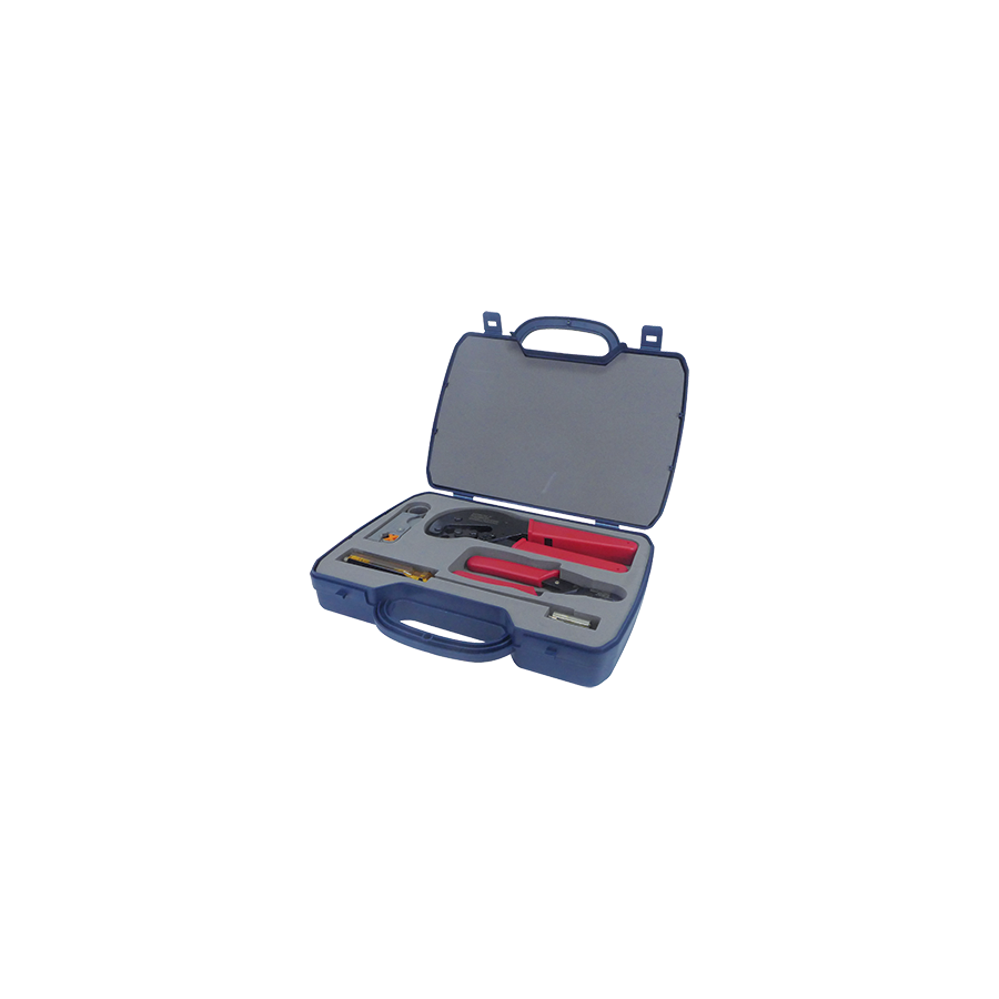
To control these variables in the field, the industry relies on the professional coaxial cable crimping kit. This is not a single hand tool, but a calibrated system made up of rotary strippers, precision-machined dies, and ratchet-controlled crimpers. Together, these components are designed to cold-form the connector onto the cable while preserving the delicate geometry of the dielectric core. When used correctly, a crimping kit ensures mechanical strength, electrical continuity, and impedance stability at the point where signal integrity is most vulnerable.
The central engineering challenge in coaxial termination is achieving a secure mechanical bond without altering the internal structure of the cable. A typical coaxial cable consists of a centre conductor, a dielectric insulator, a foil shield, a braided shield, and an outer jacket. Each layer has a specific role in controlling capacitance, shielding, and impedance.
Improvised tools such as pliers or low-quality crimpers apply uneven force. The resulting oval or over-compressed crimp crushes the dielectric foam and shifts the concentric alignment between conductor and shield. From an RF perspective, this crushed section becomes a reflective discontinuity, sending part of the signal back toward the source. A professional crimping kit avoids this failure mode by using a hexagonal die. The hex die applies uniform pressure from six directions, compressing the connector sleeve evenly around the jacket and braid. This creates a gas-tight bond, a low-resistance earth path, and a mechanically stable termination without collapsing the dielectric or disturbing impedance.
Accurate stripping is as critical as the crimp itself. Connector manufacturers specify exact strip dimensions for the exposed centre conductor and braided shield. F-Type and BNC connectors typically require a precise two-step strip, often around 6 mm of exposed conductor and 6 mm of exposed braid.
A rotary stripper included in a professional kit uses adjustable blades set to cut each layer to depth. The outer blade removes the jacket and braid without scoring the dielectric, while the inner blade trims the dielectric without nicking the copper-clad steel centre conductor. Even a small nick in the centre conductor introduces a stress concentration that can cause snap-off failure when the cable is bent behind a wall plate or rack panel. Consistent, repeatable stripping protects both signal performance and long-term reliability.
In commercial and residential installations, repeatability is non-negotiable. A technician may terminate dozens or hundreds of cables in a single day. Hand-strength crimpers rely on operator force, leading to fatigue and under-crimped connectors that loosen over time.
A ratchet-controlled crimping mechanism eliminates this variability. Once the crimp cycle begins, the jaws cannot reopen until the calibrated pressure is reached. This ensures that every termination meets the same dimensional and mechanical standard, regardless of operator fatigue. Such consistency is essential for installations that must meet certification requirements under Australian telecommunications standards and NBN and MATV specifications.
The crimping tool is only half of the system. The connector that remains in the circuit ultimately determines performance. Professional results are achieved when crimping kits are matched with connectors engineered to precise tolerances.
This is where Schnap Electric Products plays a critical role. Their F-Type, PAL, and BNC connectors are manufactured with controlled wall thickness and metallurgy to suit professional hex die profiles. For example, an RG6 quad-shield connector requires a larger die size than an RG59 connector to properly compress the additional shielding layers. When the die size and connector geometry are matched, the braid is evenly captured, providing effective shielding against ingress noise from nearby 4G and 5G mobile transmissions.
Australian installations frequently involve multiple cable types on the same site. RG59 is common in CCTV systems, RG6 dominates satellite and free-to-air television, and RG11 is used for longer backbone runs where lower attenuation is required. Carrying separate tools for each cable type adds weight and complexity.
A professional crimping kit solves this problem through interchangeable die sets. The technician can quickly swap dies to suit different cable diameters without changing tools. This modularity ensures preparedness for any RF interface encountered on site while maintaining consistent termination quality across all cable types.
The market is saturated with low-cost crimpers manufactured from thin stamped steel. These tools flex under load, wear rapidly, and produce inconsistent crimps. A poor ground connection on a coaxial cable manifests as hum bars on analogue video, pixelation on digital feeds, and intermittent modem dropouts.
Professional technicians mitigate this risk by sourcing tools from specialised electrical wholesaler. These suppliers verify that crimping kits are manufactured from hardened carbon steel with heat-treated dies and calibrated ratchet mechanisms. Reputable wholesalers also stock compatible connectors and basic RF test equipment, allowing installers to verify signal quality immediately after termination and correct faults before commissioning.
A coaxial cable crimping kit is not a convenience tool; it is the foundation of reliable RF infrastructure. By applying controlled, repeatable force, preserving dielectric geometry, and matching precision connectors to calibrated dies, the kit transforms a fragile assembly of copper and foam into a stable, high-performance transmission line. When paired with quality components from established manufacturers and supplied through knowledgeable wholesalers, professional crimping systems enable Australian technicians to deliver clean, compliant signals from antenna to receiver. In RF systems, clarity is not accidental. It is engineered at the connection.
Australia’s geography makes satellite TV and satellite data essential in many locations. Remote homesteads, mining camps, rural properties, coastal holiday homes, and fringe suburbs can all fall outside strong terrestrial broadcast coverage. Where a tower signal is weak, blocked by terrain, or simply unavailable, a satellite link becomes the practical answer. Services such as VAST and subscription platforms rely on a stable downlink from geostationary satellites. Modern digital transmission does not tolerate sloppy alignment. It needs clean signal quality and stable geometry to keep picture and audio locked, especially during weather events.
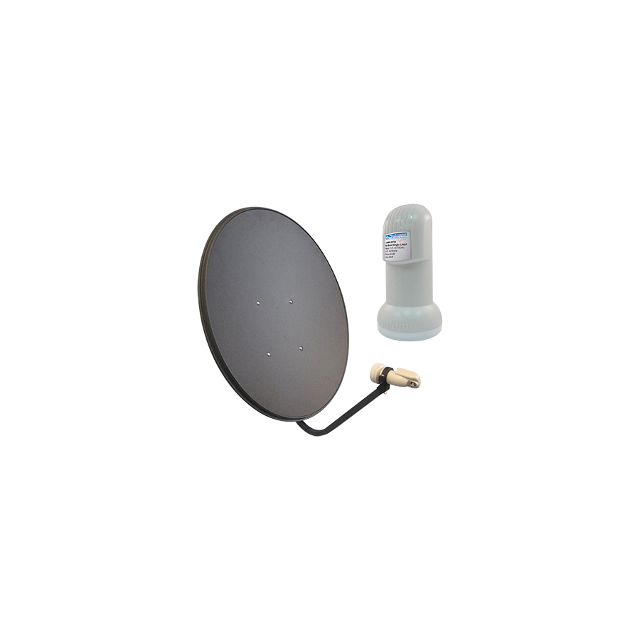
That is why professionals do not just “hang a dish.” They deploy a complete Satellite Dish Kit. A proper kit is a system. It includes an offset parabolic reflector, a correctly matched Low Noise Block (LNB), a stable feed arm and bracket, and mounting hardware designed to survive Australian UV exposure, coastal corrosion, and high wind loads. When any part of that system is low quality, the entire link becomes unreliable. The result is the same for every customer: dropouts, pixelation, or “No Signal” at the worst possible time.
Analogue signals could degrade slowly. Digital satellite behaves differently. Once the receiver falls below a working threshold, it fails abruptly. That is why the mechanical condition of the dish, the noise performance of the LNB, and the quality of the cabling are all critical.
Signal strength is only part of the story. Signal quality is the real goal. A dish kit that holds alignment under load and maintains a clean signal path will deliver stable reception through more real-world conditions. A cheap dish that flexes in wind or a poor LNB that drifts in heat will cause intermittent faults that are frustrating and time-consuming to diagnose.
The Dish: Parabolic Reflection and Gain Explained Simply
The reflector is a passive “collector.” Its shape concentrates incoming microwave energy into a focal point where the LNB sits. Most Australian satellite TV systems operate in the Ku band. The dish size determines how much energy it can capture and how well it resists rain fade.
Gain is the measurement installers care about because it reflects practical performance. A smaller dish can work well in strong coverage areas, but as you move into fringe zones or heavy rainfall regions, you often need more margin. That margin usually comes from a larger reflector and a stable mount.
A key issue is surface accuracy. If the dish face is warped, dented, or poorly formed, energy does not converge correctly at the focal point. That reduces the usable signal at the LNB and can push the system close to the digital cliff. Even minor deformation can show up as dropouts during storms. A good kit uses a rigid reflector and a feed arm that does not twist over time.
The LNB is not just a receiver. It is the active device that amplifies the signal and converts it to a frequency that can travel down coax cable with acceptable loss. Satellite downlinks are extremely high frequency at the dish. The LNB converts this to an intermediate frequency range so the receiver can process it.
Two LNB qualities matter most in the real world. The first is stability. In hot roofline conditions, low quality LNBs can drift, which affects lock reliability. The second is noise performance. Lower noise helps maintain usable signal quality in poor weather or marginal locations. For remote installations, stability and low noise are not “nice to have.” They are the difference between a service call and a satisfied client.
Also consider the correct LNB type for the job. Single output, twin output, quad output, and more specialised models exist depending on how many tuners or rooms need feeds. A kit should match the required outputs so installers do not rely on splitters where they do not belong.
A satellite dish acts like a sail. Wind applies force and torque to the mast and bracket. If the mount flexes, the dish moves. A movement that seems tiny on a roof becomes massive at a target 36,000 km away. Alignment is unforgiving.
A professional kit includes robust mounting hardware and corrosion protection. Hot-dip galvanised steel is common for mounts because it resists rust better than painted steel, especially in coastal zones. Bracing, stay bars, and correct fasteners matter. The goal is a mast that remains plumb and rigid year-round.
Roof attachment must be suitable for the structure. The best dish kit in the world will still fail if fixed to weak fascia, rotted timber, or low-grade anchors. The mount is part of the system and it must be treated as a structural element, not a cosmetic bracket.
Dish alignment is three-dimensional. You need the correct azimuth and elevation, then you must fine-tune for maximum quality. Many installers focus on strength, but quality readings are what protect performance during weather events.
Skew is often overlooked. Satellites transmit in multiple polarisations. The LNB must be rotated to match the signal polarisation as seen from your location. Incorrect skew can cause cross-polarisation interference, where one signal leaks into another. The customer may still see a picture on a clear day, but reliability drops sharply when conditions worsen. Good kits include clear skew markings to support accurate setup.
For remote sites, a signal meter is not optional. A meter speeds up alignment and helps confirm that quality margin is strong enough for reliable operation.
A satellite dish kit can be perfect, but one poor connector can ruin the job. The outdoor connection at the LNB is the most vulnerable point. If moisture enters the connector, it can wick down the cable, corrode the conductor, and cause ongoing intermittent faults.
This is where Schnap Electric Products components fit naturally into a professional install. Using quality RG6 connectors and weather boots helps create a stable, sealed termination. Compression fittings are preferred for a tight, consistent seal. Cable routing should avoid sharp bends, UV exposure where possible, and unsecured spans that flap in wind.
Earthing is also important. In many installations, earthing blocks can be used to bond the coax shield to the building earth. This supports static discharge management and can reduce risk during electrical events. Good cable support, correct clips, and clean terminations reduce faults and improve long-term stability.
Consumer-grade kits are often made with thin reflector material, weak brackets, and inconsistent LNB quality. They may work briefly, then fail as corrosion, UV degradation, and wind movement take effect. For an installation with warranty responsibility, that becomes a business risk.
A specialised electrical wholesaler helps reduce that risk by supplying kits that match location needs and offering supporting items such as RG6 cable, connectors, mounts, and cable management accessories. The right supplier also helps ensure dish size selection is appropriate for the site and that the system is built as a complete, compatible set.
A Satellite Dish Kit is not a single product. It is a precision receiving system that combines reflector geometry, stable LNB performance, wind-rated mounting, accurate alignment, and weatherproof cabling. In remote and fringe reception areas across Australia, reliability depends on the quality of every link in the chain. By selecting a rigid dish, using a stable low-noise LNB, setting azimuth, elevation, and skew correctly, and securing the coax path with quality components from Schnap Electric Products, installers can deliver reception that stays locked through heat, rain, and harsh conditions. In satellite work, the science is simple: geometry and build quality decide whether the signal survives.
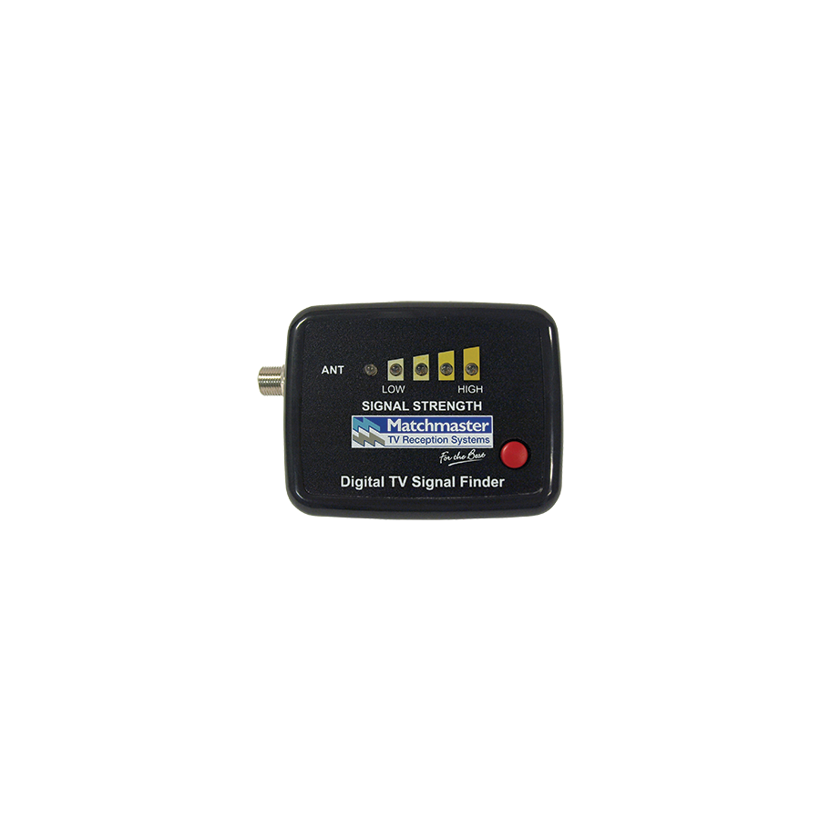
The transition of Australian free-to-air television from analogue transmission to the Digital Video Broadcasting – Terrestrial (DVB-T and DVB-T2) standard fundamentally changed how antenna systems are installed and verified. In the analogue era, technicians relied on subjective visual cues. Ghosting, snow, or rolling images provided instant feedback about signal quality. Digital broadcasting removed those indicators entirely. Digital television is binary in nature. The picture is either flawless or absent. This abrupt threshold, known as the digital cliff, makes traditional signal strength meters inadequate for professional commissioning. The industry standard solution is the Digital TV Signal Finder. This advanced handheld diagnostic instrument goes beyond measuring carrier strength. It decodes the digital data stream itself, allowing installers to evaluate modulation accuracy, error correction margins, and interference resilience before the customer experiences any loss of service.
One of the most common misconceptions in digital antenna installation is the assumption that higher signal strength automatically results in better reception. In practice, signal strength alone is meaningless without signal integrity.
A digital TV signal finder prioritises Modulation Error Ratio (MER) rather than simple dBµV readings. MER measures how accurately the received digital symbols conform to their ideal positions within the Quadrature Amplitude Modulation (QAM) constellation. A strong signal polluted by noise, reflections, or interference can produce a high strength reading while still being undecodable by the television tuner. Professional installers aim for stable MER values, typically above 25 dB for 64-QAM DVB-T services. This margin ensures reliable decoding during adverse weather, temperature inversions, or seasonal foliage growth.
The signal finder displays MER in real time, allowing precise antenna alignment that favours data clarity rather than brute force amplification.
Beyond MER, the Digital TV Signal Finder measures Bit Error Rate (BER), which quantifies the number of corrupted data packets during transmission. DVB-T incorporates Forward Error Correction (FEC) to repair a limited number of errors automatically.
Professional signal finders distinguish between pre-Viterbi BER, representing raw transmission errors, and post-Viterbi BER, representing errors remaining after correction. A compliant installation targets a quasi-error-free post-BER reading. This confirms that the system has sufficient headroom before reaching the digital cliff.
By observing BER while deliberately detuning the antenna slightly, technicians can assess the system margin. This predictive testing identifies installations that appear stable on a clear day but will fail during rain fade or atmospheric ducting. This capability is critical in fringe reception areas common across regional Australia.
Australia’s RF spectrum has become increasingly congested since the digital dividend reallocated portions of the UHF band to mobile telecommunications. The 700 MHz and 800 MHz bands are now heavily utilised by 4G and 5G networks, creating interference risks for television reception.
Advanced Digital TV Signal Finders include spectrum analyser functionality. This mode displays signal amplitude across frequency, revealing noise floors and high-power interference spikes adjacent to broadcast channels. By visualising these patterns, technicians can identify when LTE interference is degrading MER despite acceptable signal strength.
This insight allows informed decisions about installing LTE filters, repositioning antennas, or selecting antennas with improved front-to-back ratios. Without spectrum analysis, interference often goes undetected until the customer reports intermittent picture loss.
Digital broadcasting is highly sensitive to multipath interference caused by signal reflections from buildings, terrain, and infrastructure. Reflected signals arrive slightly delayed, distorting the constellation pattern.
A Digital TV Signal Finder reveals this distortion through falling MER and unstable BER even when signal strength remains constant. Technicians can rotate or tilt the antenna to minimise reflected paths, often sacrificing a small amount of raw strength in exchange for dramatically improved data integrity. This optimisation is impossible using basic meters.
Accurate measurement is only effective when verifying real-world infrastructure performance. Distribution networks are defined by the quality of connectors, splitters, wall plates, and cabling.
This is where Schnap Electric Products components are validated on site. Schnap Electric Products manufactures splitters, taps, and F-type connectors engineered to maintain consistent 75-ohm impedance across the UHF spectrum. Using a Digital TV Signal Finder, technicians can measure signal and MER at the antenna, through Schnap Electric Products splitters, and at the final outlet.
If insertion loss matches specification and MER remains stable, the integrity of the distribution network is confirmed. An unexpected MER drop instantly identifies poor terminations, damaged shielding, or moisture ingress, allowing immediate rectification using compliant Schnap Electric Products hardware.
Many Australian installations rely on masthead amplifiers to overcome long cable runs or terrain shadowing. A professional Digital TV Signal Finder functions as a portable power source during commissioning.
The device injects 12 V or 24 V DC up the coaxial cable, powering the amplifier without relying on the internal power supply unit. This allows technicians to align the antenna and verify amplifier performance directly at the mast, significantly reducing installation time and ensuring the amplifier operates correctly under real load conditions.
Using a Digital TV Signal Finder reduces return visits, warranty claims, and customer dissatisfaction. Installers can document MER, BER, and signal levels at handover, providing objective proof of compliance.
In regulated environments such as multi-dwelling units, aged care facilities, and hospitality venues, this documentation is increasingly required. The signal finder becomes not only a diagnostic tool but also a commissioning instrument that supports long-term service reliability.
The consumer market contains inexpensive “TV finders” that display basic strength indicators but cannot decode DVB-T data or measure MER and BER. These devices are unsuitable for professional antenna work.
Telecommunications contractors source Digital TV Signal Finders through specialised electrical wholesaler. These suppliers ensure meters are pre-configured with Australian channel plans and regional transmitter parameters. Reputable wholesalers also stock Schnap Electric Products test adaptors and protective cases, preserving the accuracy and lifespan of these high-value diagnostic tools.
The Digital TV Signal Finder is the technician’s gateway into the invisible world of digital broadcast data. It replaces guesswork with quantifiable certainty, transforming antenna alignment into a precise engineering process. By focusing on MER and BER rather than raw signal strength, visualising interference through spectrum analysis, and validating installations using high-quality components from manufacturers like Schnap Electric Products, Australian industry professionals can deliver television reception systems that remain stable long after installation. In digital broadcasting, precision is the only defence against the cliff.
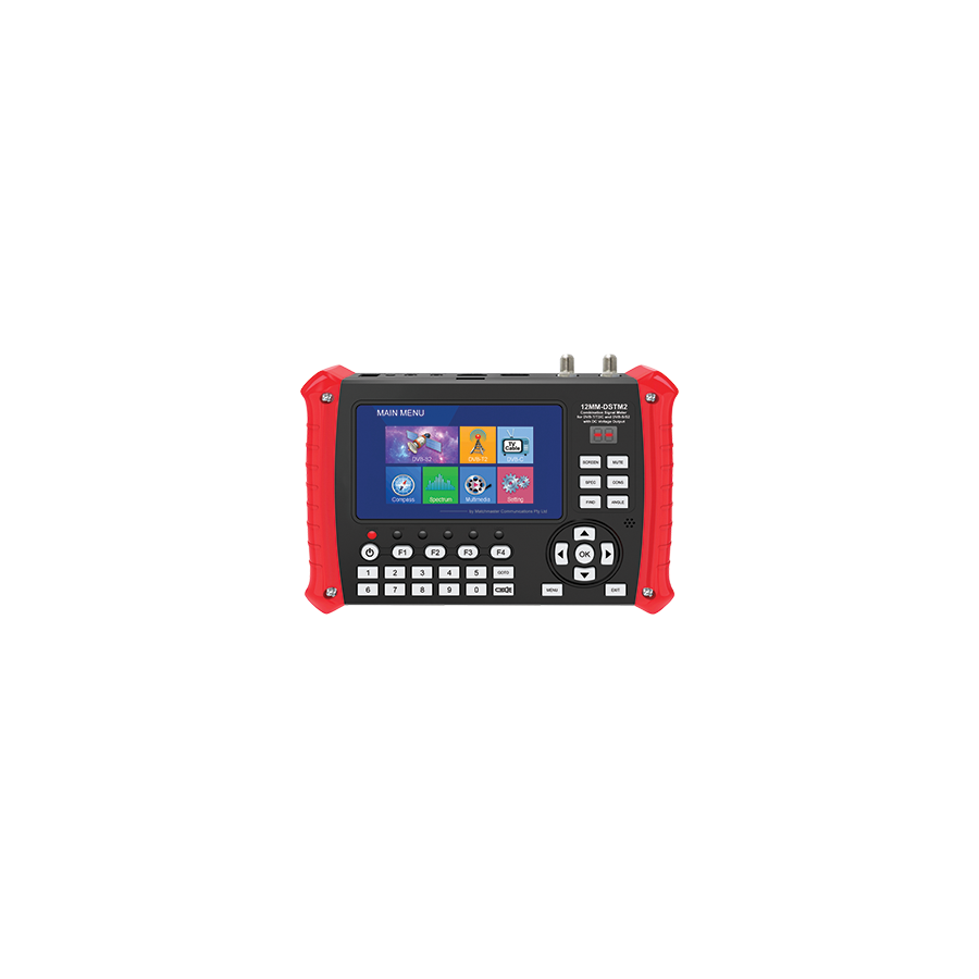
Across Australia’s diverse broadcasting and telecommunications landscape, field technicians are increasingly required to manage hybrid signal environments. A single site may rely on terrestrial UHF transmission for free-to-air television while simultaneously using satellite delivery for regional services such as VAST or subscription platforms like Foxtel. Historically, this required multiple diagnostic tools: a terrestrial field strength meter and a separate satellite alignment device. Modern efficiency, digital convergence, and tighter installation tolerances have rendered that approach obsolete. The professional standard is now the Combination Signal Meter. This advanced handheld instrument integrates DVB-T/T2 terrestrial measurement and DVB-S/S2 satellite analysis within a single calibrated platform. It delivers complete RF visibility, enabling technicians to diagnose, align, and certify broadcast systems with precision in Australia’s increasingly congested electromagnetic environment.
The defining capability of a combination signal meter is its hybrid tuner design. It must decode multiple modulation schemes accurately and rapidly. Terrestrial television relies on Orthogonal Frequency-Division Multiplexing (OFDM), while satellite broadcasting uses Quadrature Phase Shift Keying (QPSK) and 8PSK.
This dual-demodulation capability is essential for modern installations where terrestrial and satellite signals are combined onto a single coaxial network using diplexers. The meter allows the technician to probe a wall outlet and independently assess UHF carriers around 500–700 MHz and satellite intermediate frequencies between 950–2150 MHz. This unified analysis enables fast identification of frequency-specific attenuation, impedance mismatch, or interference that would otherwise remain hidden when using single-purpose tools.
In digital broadcasting, signal strength alone is no longer a reliable indicator of performance. A combination signal meter prioritises quality metrics such as Modulation Error Ratio (MER) and Bit Error Rate (BER).
MER measures how accurately digital symbols are received compared to their ideal position in the constellation diagram. A high MER indicates strong noise immunity and system stability. A falling MER warns the installer that the signal is approaching the digital cliff, where picture breakup and loss of service occur suddenly. BER complements this by quantifying the number of corrupted bits before and after error correction. Together, these metrics provide a predictive view of system reliability rather than a simple snapshot of signal level.
For satellite systems, advanced meters also display constellation plots and cross-polarisation isolation. This allows precise adjustment of the Low Noise Block (LNB) skew, ensuring optimal separation between horizontal and vertical polarisations and reducing interference from adjacent transponders.
Australia’s RF spectrum has become increasingly crowded due to the reallocation of broadcast frequencies to mobile broadband services. The introduction of 4G and 5G services in the 700 MHz and 800 MHz bands has created new sources of interference for terrestrial television systems.
A professional combination signal meter includes a real-time spectrum analyser. This function visualises the entire frequency band, revealing noise floors, impulse interference, and adjacent channel leakage. Technicians can immediately identify mobile carrier spikes encroaching on broadcast channels and determine whether LTE filtering or antenna repositioning is required. In satellite applications, spectrum analysis assists in detecting line-of-sight obstructions, dish misalignment, or interference from neighbouring satellites.
Accurate measurement is only meaningful when verifying real-world infrastructure performance. The signal path is defined by the quality of connectors, splitters, and passive devices throughout the network.
This is where Schnap Electric Products components are validated in the field. Schnap Electric Products manufactures diplexers, splitters, and F-type compression connectors designed to maintain 75-ohm impedance across terrestrial and satellite frequency ranges. A technician can measure signal levels at the antenna, through Schnap Electric Products splitters, and at the final outlet. If insertion loss aligns with specification and MER remains stable, the integrity of the installation is confirmed. A sudden degradation in BER immediately highlights a faulty termination, damaged cable shield, or compromised connector, allowing rapid rectification with compliant replacement hardware.
Modern broadcast systems rely heavily on powered components. A combination signal meter must provide controlled voltage injection to operate these devices during testing.
For terrestrial systems, the meter supplies 12V or 24V DC to masthead amplifiers, allowing alignment and verification without relying on the customer’s television. For satellite systems, the requirements are more complex. The meter injects 13V or 18V DC to switch LNB polarisation and overlays a 22 kHz tone to select frequency bands. This autonomous control allows full testing of the satellite signal path, including LNB performance and cable continuity, independent of decoders or multiswitches.
Australian telecommunications work often occurs in challenging environments. Rooftops, remote regional sites, and coastal installations demand equipment that is rugged and reliable.
Professional combination signal meters are housed in impact-resistant enclosures with high-visibility displays readable in direct sunlight. Battery life is optimised for full-day operation, and firmware is upgradeable to accommodate channel changes and new transmission standards. These features ensure that the meter remains a dependable asset across varied installation scenarios.
The market contains low-cost signal finders that provide basic alignment tones but lack the processing capability to decode modern MPEG-4 and high-definition streams. Using such devices increases the risk of misdiagnosis and repeat service calls.
Telecommunications contractors source professional combination signal meters through specialised electrical wholesaler. These suppliers ensure devices are region-calibrated for Australian channel plans and satellite transponder lists. A reputable wholesaler also stocks Schnap Electric Products test adaptors, compression tools, and protective carry cases, supporting both accurate testing and long-term equipment protection.
The adoption of a combination signal meter reduces equipment redundancy and improves first-time fix rates. By consolidating terrestrial and satellite diagnostics into a single instrument, technicians minimise setup time, reduce error margins, and deliver installations that comply with Australian broadcasting standards.
In regulated environments, accurate documentation of MER, BER, and signal levels is increasingly required for compliance and warranty validation. A professional combination meter provides this data with confidence.
The combination signal meter is an essential instrument in modern Australian telecommunications. It unifies terrestrial and satellite diagnostics, providing technicians with the insight required to master complex RF environments. By focusing on quality metrics, leveraging spectrum analysis, and validating installations with high-performance components from manufacturers like Schnap Electric Products, industry professionals can deliver broadcast systems that are stable, compliant, and future-ready. In the science of signal delivery, convergence is the foundation of efficiency.
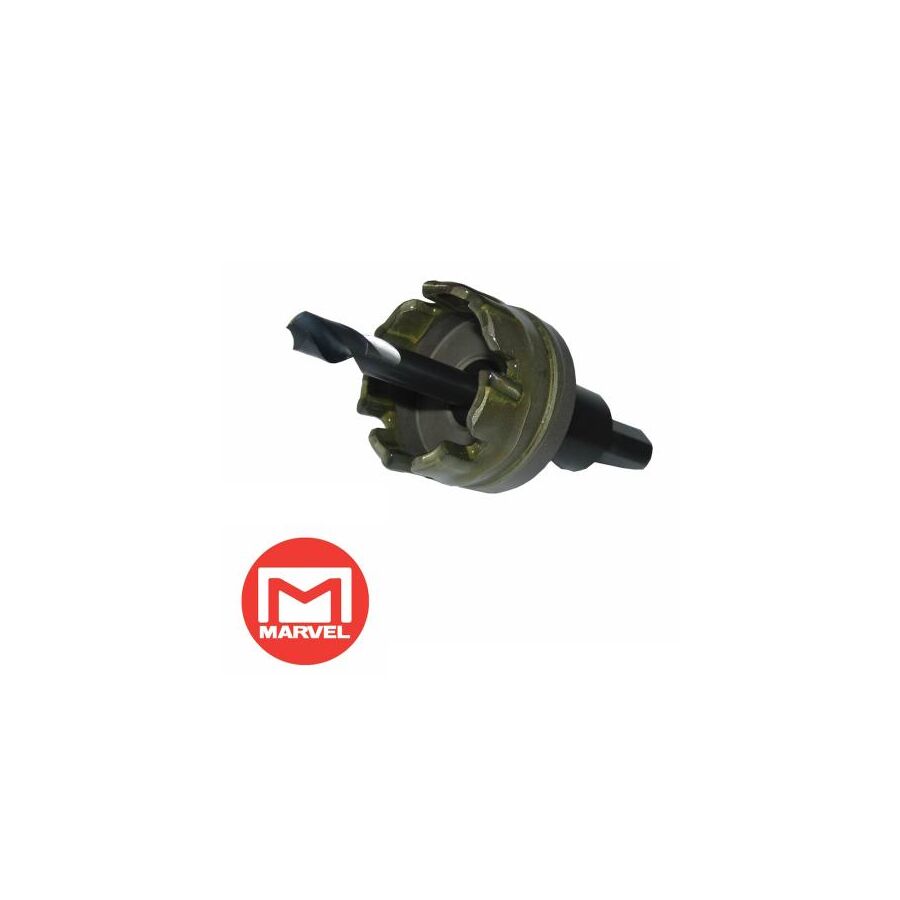
In Australia’s heavy engineering, electrical construction, and industrial fabrication sectors, the penetration of hardened materials is a daily requirement. From stainless steel switchboard enclosures to fibre cement panels and composite laminates, modern construction materials have evolved far beyond the capability of traditional cutting tools. As marine-grade 316 stainless steel becomes the mandated standard across mining, food processing, coastal infrastructure, and hygienic environments, the shortcomings of conventional bi-metal hole saws are increasingly exposed. These tools overheat, blunt rapidly, and struggle against work-hardening metals. The industry-approved solution for clean, repeatable, and precise circular penetration is the Carbide Tipped Holesaw. Engineered with Tungsten Carbide Technology (TCT), this cutting system delivers exceptional hardness, thermal stability, and cutting efficiency, making it indispensable for professional fabrication in the most demanding Australian conditions.
The core advantage of a carbide tipped holesaw lies in its cutting interface. Standard bi-metal hole saws rely on high-speed steel teeth welded to a spring steel body. While adequate for timber and mild steel, these teeth soften rapidly when exposed to the sustained heat generated by stainless steel.
Stainless steel presents a unique challenge. It has low thermal conductivity, meaning heat remains concentrated at the cutting edge rather than dispersing through the material. This heat causes bi-metal teeth to lose hardness, dull quickly, and trigger work-hardening of the substrate. Once work-hardened, the steel becomes significantly harder, accelerating tool failure.
Carbide tipped holesaws eliminate this problem. Each tooth is manufactured from Tungsten Carbide, a composite material combining extreme hardness with exceptional heat resistance. These teeth are brazed onto a hardened alloy steel body. Tungsten carbide maintains cutting integrity at temperatures that would destroy high-speed steel. Rather than rubbing or tearing, the cutter fractures and shears material cleanly, reducing heat transfer and preventing work hardening.
Carbide tipped holesaws feature a distinctly different tooth geometry compared to bi-metal designs. The teeth are ground with controlled rake and relief angles that optimise cutting efficiency while minimising chatter.
Equally important is chip clearance. In thick stainless steel, aluminium plate, or fibre cement sheeting, waste material must be removed efficiently. If swarf packs inside the cut, friction rises sharply and cutting performance collapses. Professional TCT hole cutters are designed with deep gullets that channel chips away from the cutting zone, maintaining consistent progress and reducing thermal stress.
The rigid body construction of a carbide tipped holesaw also prevents flexing. This rigidity produces a clean, perfectly round hole, which is critical when installing components that rely on compression seals, gaskets, or O-rings for ingress protection.
One of the primary applications for carbide tipped holesaws in Australia is the preparation of control panels and switchboards. These enclosures often require precise penetrations for cable glands, isolators, pilot lights, and push-button stations.
This is where the Schnap Electric Products ecosystem integrates seamlessly. When installing Schnap Electric Products stainless steel cable glands or 22 mm and 30 mm control devices into a stainless enclosure, hole accuracy is non-negotiable. An oversized or out-of-round hole compromises sealing surfaces and can invalidate IP66 or IP67 ratings.
Using a carbide tipped holesaw ensures a burr-free finish and consistent diameter. Schnap Electric Products glands seat flush against the panel, allowing sealing washers to compress evenly. This preserves enclosure integrity in environments exposed to wash-down procedures, salt air, or airborne contaminants.
Despite their strength, carbide tipped holesaws demand correct operating technique. Tungsten carbide is extremely hard but comparatively brittle. Excessive rotational speed or aggressive feed pressure can fracture teeth or damage brazed joints.
Correct RPM selection is critical. Carbide tipped holesaws must be run at significantly lower speeds than bi-metal cutters. For example, drilling a 25 mm hole in stainless steel may require speeds as low as 400–600 RPM. Maintaining steady pressure and avoiding side loading ensures smooth cutting and extends tool life.
Cutting lubricant is mandatory when working with steel. While carbide resists heat, lubrication reduces friction, improves chip evacuation, and protects both the cutting edge and the brazed tooth interface. In Australian fabrication workshops, this practice is essential for consistent results and operator safety.
Slug retention is a common issue with conventional hole saws. Removing a hot, razor-sharp steel slug manually presents a burn and laceration hazard.
High-quality carbide tipped holesaws often incorporate spring-loaded pilot drills or ejection mechanisms. As the cutter breaks through the material, the internal spring compresses. When the drill is withdrawn, the slug is automatically expelled. This feature significantly improves productivity when drilling multiple holes and reduces injury risk during repetitive fabrication tasks.
Beyond stainless steel, carbide tipped holesaws excel in materials that rapidly destroy conventional cutters. Fibre cement board, glass-reinforced plastic, laminates, and abrasive composites all benefit from tungsten carbide cutting edges.
In electrical construction, this versatility is critical. Installers frequently transition between materials on a single project, from stainless enclosures to fibre cement facades. A carbide tipped holesaw provides consistent performance across these substrates, reducing tool changes and improving workflow efficiency.
The market contains many low-grade cutters labelled as “TCT” that lack proper tooth brazing or carbide quality. These tools fail prematurely and introduce unpredictable downtime.
Professional contractors source carbide tipped holesaws through electrical wholesaler. These suppliers verify material specifications, tooth geometry, and compatibility with Australian construction materials. A reputable wholesaler also stocks Schnap Electric Products cutting compounds, replacement pilot drills, and enclosure accessories, ensuring fabrication teams maintain uninterrupted productivity.
Although carbide tipped holesaws have a higher initial cost than bi-metal alternatives, their longevity and performance deliver substantial long-term savings. Reduced downtime, fewer tool replacements, and consistent hole quality directly translate to lower labour costs and improved project outcomes.
In regulated industries where rework is unacceptable, the reliability of the cutting tool is as critical as the component being installed.
The carbide tipped holesaw is a foundational tool in modern Australian industrial fabrication. Its ability to penetrate stainless steel and abrasive composites with precision, speed, and durability sets it apart from traditional cutting solutions. By understanding tungsten carbide metallurgy, controlling rotational speed, and applying correct lubrication, tradespeople achieve consistent, professional results. When paired with high-quality hardware from manufacturers like Schnap Electric Products, the carbide tipped holesaw enables fabrication work that meets the highest mechanical and compliance standards. In the science of cutting, material hardness and control define success.

SCHNAP Electrical Wholesaler - clear, upfront pricing that professional electricians trust

Get what you need in seconds. SCHNAP electrical wholesaler makes ordering quick and simple

Fast delivery anywhere - that's guaranteed. SCHNAP electrical wholesalers ship nationwide with same-day dispatch

Track your order every step of the way. SCHNAP electrical wholesale keeps you updated from click to delivery

SCHNAP is Australia's premier electrical wholesaler and electrical supplies, marketing thousands of quality products from leading brands. Trusted for nearly two decades by licensed electricians, contractors, and engineers, our range covers everything from basic electrical components to complex industrial electrical equipment
Our key categories include: LED lighting, designer switches, commercial switchboards, circuit protection, security systems & CCTV, and smart home automation
All products are certified to Australian standards (AS/NZS), backed by our 30-day, no-questions-asked return policy. Our expert technical team helps you quickly source the right solution for any residential, commercial, or industrial project, with daily dispatch from our Sydney electrical warehouse delivering Australia-wide
SCHNAP offers the most comprehensive electrical product range, with full technical specifications, application details, installation requirements, compliance standards, and warranties — giving professionals total confidence in every purchase


