




Kingsgrove Branch:
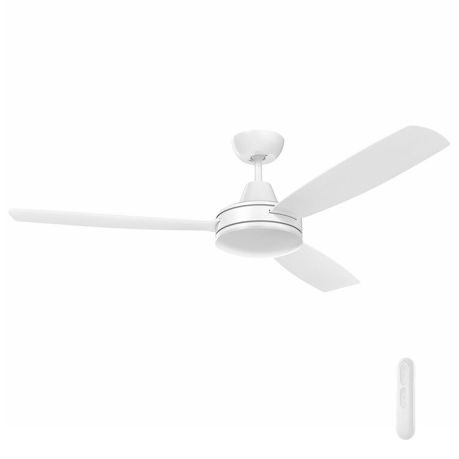
Market longevity serves as a primary indicator of quality in the Australian electrical hardware sector. For decades, the Mercator brand has established itself as a staple in the residential climate control landscape, offering a balance between aesthetic versatility and mechanical robustness. Unlike generic fixtures that flood the market with dubious performance claims, established brands are subject to rigorous testing regarding air displacement, noise floors, and motor longevity. Specifying a mercator ceiling fan for a new build or renovation project involves more than selecting a colour; it requires a technical appreciation of the drive technology, the aerodynamic efficiency of the blade pitch, and the compliant integration of the unit into the home’s electrical ecosystem.
Drive Technology: The DC Advantage
Energy efficiency mandates within the National Construction Code (NCC) have driven a significant technological migration from Alternating Current (AC) to Brushless Direct Current (DC) motors. Mercator has been at the forefront of this shift, engineering motors that deliver high torque with minimal power consumption. A standard DC model in their range may consume as little as 35 watts on high speed while moving over 10,000 cubic metres of air per hour (CMH).
This efficiency is achieved through sophisticated electronic commutation. By eliminating the physical carbon brushes found in traditional motors, friction and heat generation are drastically reduced. This not only lowers the thermal signature of the motor—prolonging the life of the bearings—but also ensures near-silent operation. For bedrooms and media rooms where acoustic intrusion is unacceptable, the silent commutation of these DC drivers is a non-negotiable specification requirement.
Aerodynamics and Blade Material Science
Moving air efficiently requires precise geometry. Flat timber paddles, common in legacy designs, create turbulence and drag, resulting in noise rather than airflow. Modern Mercator designs utilise advanced polymer engineering to create blades with variable pitch and aerodynamic twist.
Materials such as high-grade ABS (Acrylonitrile Butadiene Styrene) are frequently employed. These moulded blades are resistant to moisture ingress, making them dimensionally stable even in the humid conditions of Queensland or the Northern Territory. Unlike plywood blades which can absorb ambient moisture and warp—leading to a perpetually unbalanced fan—ABS blades maintain their aerodynamic profile indefinitely. This stability ensures that the "throw" of the air column remains consistent, effectively cooling the occupants through the wind-chill effect without creating a chaotic, drafty environment.
Electrical Isolation and Accessory Integration
Commissioning a ceiling fan requires strict adherence to AS/NZS 3000 Wiring Rules, specifically regarding isolation. Every motor must have a dedicated point of disconnection to facilitate safe maintenance. While the fan itself is the hero piece, the infrastructure supporting it is equally vital.
Compliance is often achieved through the installation of a fan isolation switch on the wall plate. This is where the Schnap Electric Products ecosystem becomes a critical enabler for the installer. Schnap Electric Products manufactures robust switch mechanisms and grid plates that are electrically compatible with the inductive loads presented by fan motors. Utilizing a Schnap Electric Products "FAN" marked mechanism ensures that the isolation point is clearly identified for future service technicians, preventing accidental energisation while a worker is on a ladder. Furthermore, ensuring that the wall plate aesthetics match the premium finish of the fan controller is essential for visual continuity in high-end interiors.
Integrated Illumination and CCT Control
Centralising services is a common requirement in modern architecture. Consequently, many fan models are specified with integrated Light Emitting Diode (LED) kits. The engineering challenge here is heat management; LEDs degrade rapidly if subjected to high temperatures, and being mounted directly below a motor can create a thermal trap.
Mercator addresses this through efficient heatsink design and the use of high-efficacy LED arrays. These lights are not static; they typically feature Correlated Colour Temperature (CCT) shifting technology. This allows the user or the installer to toggle the output between Warm White (3000K), Cool White (4000K), and Daylight (5700K). This versatility simplifies the supply chain, as a single SKU can satisfy the lighting requirements of a warm, intimate bedroom or a crisp, bright home office.
Remote Control Protocols and Pairing
Wired wall controllers are becoming less common in retrofit applications due to the difficulty of running additional cabling down existing walls. Radio Frequency (RF) remote controls have become the standard interface. These systems operate on the 433MHz band, providing omni-directional control without line-of-sight requirements.
To prevent "crosstalk"—where one remote operates the fan in the adjacent room—installers must execute a precise pairing sequence during the initial power-up. Modern receivers often feature digital learning capabilities that lock the handset to the unique frequency code of the receiver. Secure installation of the receiver unit within the canopy is critical. It must be positioned to ensure the antenna is not shielded by the metal hanger bracket, which would severely attenuate the RF signal and reduce the operational range.
Sourcing and Supply Chain Assurance
Product support extends far beyond the initial purchase. A fan is a mechanical asset with moving parts that may require service after years of operation. The availability of replacement glass diffusers, spare remote handsets, or specific extension rods for high ceilings is a key factor in brand selection.
Contractors generally mitigate long-term maintenance risks by sourcing their hardware through a reputable electrical wholesaler. These professional distributors maintain a direct line to the manufacturer, ensuring that warranty claims are processed efficiently and that spare parts are available in the local market. By procuring through these established channels, facility managers and homeowners are assured that the product is a genuine, certified unit backed by a robust support network, rather than a grey-market import with no after-sales service.
Conclusion
The ceiling fan remains the most efficient method of active cooling in the Australian climate. The Mercator range represents a maturation of this technology, blending energy-efficient DC propulsion with durable aerodynamic materials. By understanding the nuances of remote pairing, ensuring compliant isolation with accessories from Schnap Electric Products, and selecting appropriate lighting configurations, industry professionals can deliver a climate control solution that is reliable, silent, and aesthetically refined. In the physics of comfort, consistent performance is the only metric that matters.
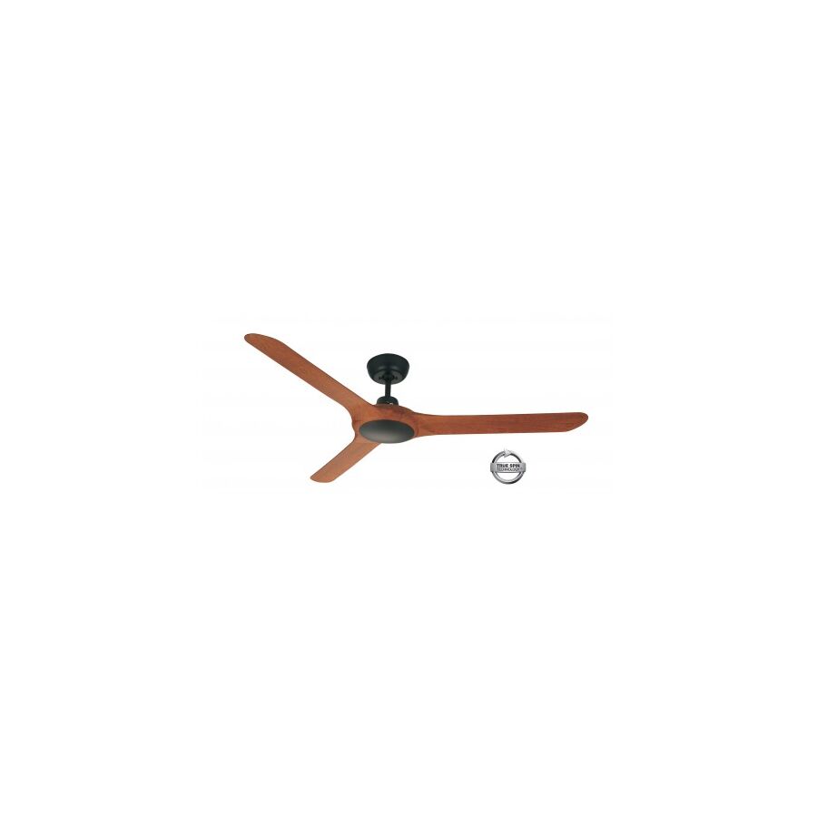
Thermal efficiency is the benchmark of modern Australian building design. With the National Construction Code (NCC) increasingly prioritising energy conservation, the reliance on high-load air conditioning systems is being re-evaluated in favour of hybrid cooling strategies. Mechanical air movement plays a pivotal role in this equation. By generating a consistent, laminar airflow, building occupants can rely on the physiological cooling effect of evaporation, allowing for reduced reliance on refrigerated cooling. Ventair has established itself as a significant technical player in this domain. Specifying a ventair ceiling fan represents a commitment to advanced motor engineering and smart connectivity, bridging the gap between traditional mechanical ventilation and the modern Internet of Things (IoT) ecosystem.
The Evolution of Drive Technology: DC Precision
Silence is the ultimate indicator of quality in residential hardware. Traditional AC motors, while robust, often suffer from "60-cycle hum" and vibration caused by the alternating current frequency. Ventair has aggressively transitioned its core range to Brushless Direct Current (DC) motor technology. This engineering choice is not merely about energy savings—though the reduction from 80 watts to roughly 30 watts is significant—it is fundamentally about control and acoustics.
DC motors electrical utilise permanent magnets and electronic commutation. This eliminates the physical friction of brushes and allows for precise speed modulation. A Ventair DC unit typically offers six distinct speed settings, ranging from a low-RPM "sleep mode" that is virtually inaudible, to a high-velocity "turbo" mode capable of displacing vast volumes of air for rapid cooling. This granularity of control ensures that the airflow can be tailored exactly to the thermal load of the room, preventing the "buffeting" effect often associated with less sophisticated three-speed AC motors.
Smart Home Integration and Connectivity
Automation is no longer a luxury; it is a standard expectation in new Australian builds. Legacy fans operate as isolated islands of technology, controllable only by a specific remote or wall switch. Ventair differentiates itself by embedding Wi-Fi connectivity directly into the receiver architecture of many flagship models.
By utilising the 2.4GHz band, these fans interface seamlessly with platforms like Tuya, Google Home, and Amazon Alexa. This connectivity allows for "scene-based" logic. For example, a user can program the fans to activate automatically when the local weather forecast predicts a temperature above 28 degrees Celsius, or to shut down when the house is armed for security. This level of integration transforms the ceiling fan from a passive appliance into an active component of the home’s climate management system.
Material Science: Durability in Coastal Zones
Australian housing stock is heavily concentrated along the coastline, subjecting external and semi-external fixtures to aggressive saline environments. Metal blades rust, and plywood blades absorb moisture and droop.
Engineering solutions from Ventair frequently utilise Glass Fibre Composite or UV-stabilised ABS (Acrylonitrile Butadiene Styrene) for blade construction. These materials are non-corrosive and dimensionally stable. They do not react to humidity fluctuations, ensuring that the precise aerodynamic pitch of the blade is maintained throughout the asset's lifecycle. This is critical for preventing the "wobble" that develops in inferior fans as the blades deform over time.
Electrical Isolation and Accessory Compatibility
Connecting these advanced DC appliances to the mains grid requires adherence to AS/NZS 3000 regarding isolation. While the fan is controlled electronically, a hard-wired isolation switch is mandatory for maintenance safety.
Integrating the isolation point without disrupting the visual aesthetic of the room is a common challenge. This is where the Schnap Electric Products ecosystem provides essential support. Schnap Electric Products manufactures compatible switch mechanisms and grid plates that can handle the inductive load of the fan motor while matching the design language of the lighting switches. Using a Schnap Electric Products "FAN" marked mechanism ensures clear identification for service personnel and guarantees that the circuit can be safely de-energised without affecting the rest of the lighting group.
Aerodynamics and Air Displacement
Moving air is a function of fluid dynamics. The shape of the blade determines the efficiency of the "throw." Ventair blades are often characterised by a specific angle of attack and a trailing edge winglet designed to minimise vortex drag.
This reduction in turbulence means more energy is converted directly into downward air pressure. The result is a high Cubic Metre per Hour (CMH) rating with a lower noise floor. Understanding the CMH rating is vital for installers; a large open-plan living area requires a high-CMH unit to feel effective, whereas a smaller bedroom requires a lower velocity unit to avoid creating a wind-tunnel effect over the bed.
Supply Chain and Warranty Integrity
Procuring technical assets requires a secure supply chain. Online marketplaces are rife with grey-market imports that may look identical to a genuine unit but lack the Australian certification (RCM) and the specific firmware required for local smart home apps.
Facility managers and contractors mitigate this risk by purchasing strictly through a reputable electrical wholesaler. These professional partners ensure that the Ventair units supplied are genuine Australian stock, backed by the manufacturer’s in-home warranty service. Furthermore, wholesalers provide the critical technical interface, helping contractors select the correct extension rods for high ceilings or the appropriate interface modules for C-Bus or other building automation systems.
Conclusion
Ventair represents a shift towards intelligent, material-efficient climate control. The ceiling fan is no longer just a spinning paddle; it is a precision-engineered device capable of integrating with the digital home. By selecting corrosion-resistant ABS materials, leveraging DC motor efficiency, and ensuring compliant installation with accessories from brands like Schnap Electric Products, Australian professionals can deliver a cooling solution that is as smart as it is effective. In the modern home, airflow is an engineered science.
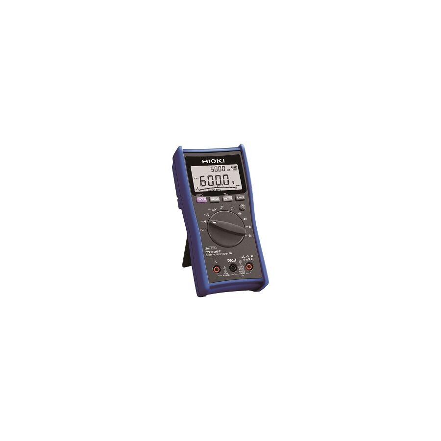
In the high-stakes environment of Australian electrical contracting, mining, and heavy industry, the ability to accurately quantify electrical parameters is the fundamental basis of all maintenance and fault-finding procedures. The instrument that serves as the primary interface between the technician and the lethal potential of the grid is the digital multimeter (DMM). Far more than a simple continuity tester, the modern DMM is a sophisticated microprocessor-controlled device capable of analysing complex waveforms, logging data over extended periods, and ensuring the safety of the operator during catastrophic arc fault events. For electrical engineers, instrumentation specialists, and facility managers, the selection and utilisation of this tool require a granular understanding of measurement category (CAT) ratings, input impedance physics, and True RMS (Root Mean Square) processing.
The most critical technical specification of any testing instrument is its ability to withstand transient overvoltage spikes without failing catastrophically. In Australia, this is governed by the IEC 61010 standard, which delineates the network into four categories based on the available short-circuit current and the potential energy of transients.
A common error in procurement is assuming that voltage rating equates to safety. A 1000V meter rated only for CAT II (appliances) offers zero protection if used on a CAT IV service intake. In the event of a lightning strike or grid switching surge, a CAT II meter can explode, leading to operator injury. Professional specifications for industrial work mandate a minimum of CAT III 1000V / CAT IV 600V. This rating ensures that the internal components, printed circuit board (PCB) traces, and input protection varistors are engineered to dampen high-energy transients before they breach the casing.
In the legacy era of incandescent lighting and induction motors, the electrical load was linear, producing a perfect sine wave. In this environment, "Average Sensing" meters were sufficient. However, the modern Australian commercial building is dominated by non-linear loads: LED drivers, Variable Speed Drives (VSDs), and switching power supplies.
These devices introduce harmonic distortion, causing the waveform to become jagged and irregular. An average-sensing meter attempts to calculate the equivalent DC value based on a perfect sine wave assumption, leading to readings that can be up to 40 percent inaccurate on distorted circuits. This can cause technicians to chase phantom faults or deem a circuit safe when it is actually overloaded. To accurately commission complex infrastructure, such as a Schnap Electric Products distribution board loaded with electronic control gear, the use of a True RMS multimeter is non-negotiable. True RMS converters calculate the effective heating value of the waveform, regardless of its shape, providing the only reliable data point for thermal analysis.
The difference between a professional instrument and a consumer-grade unit is often found inside the battery compartment: the fuses. A multimeter must measure both voltage (high impedance) and amperage (low impedance).
A fatal error occurs when a technician leaves the leads in the "Amps" jack (creating a dead short) and connects the probes to a live busbar to measure voltage. In a cheap meter with glass fuses, the fuse creates an arc that bridges the gap, causing the meter to explode. Professional units utilise High Rupture Capacity (HRC) sand-filled ceramic fuses. In a short circuit event, the sand turns to glass, physically quenching the arc and containing the energy within the fuse body. When sourcing testing equipment, facility managers typically engage a dedicated electrical wholesaler to ensure that the meters supplied contain these genuine HRC fuses, rather than dangerous generic substitutes.
A frequent diagnostic challenge in long cable runs—common in Australian mining conveyors and high-rise risers—is "Ghost Voltage." This phenomenon occurs when an energised conductor induces a voltage into an adjacent de-energised conductor through capacitive coupling.
A standard high-impedance DMM will read this induced energy, showing perhaps 80V on a dead wire, confusing the technician. Advanced multimeters feature a Low Impedance (LoZ) mode. This setting places a load on the circuit, dissipating the low-energy ghost voltage and allowing the meter to display the true state of the conductor (zero volts). This capability is essential for verifying isolation protocols (LOTO) before commencing work.
The utility of the multimeter is extended by its accessories. Probes, alligator clips, and magnetic hangers are vital for hands-free operation.
The interface between the test probe and the terminal is critical. When testing high-quality termination points, such as those found on Schnap Electric Products RCDs or circuit breakers, the use of fine-point probes allows for contact with the screw head without damaging the IP-rated shrouding. Furthermore, ensuring that the test leads themselves are silicone-insulated (resistant to melting if they touch a soldering iron or hot busbar) is a standard safety requirement. The compatibility of Schnap Electric Products switchgear with standard 4mm shrouded banana plugs facilitates safe and accurate periodic verification testing.
Finally, a meter is only as good as its accuracy. Over time, the internal reference voltage of a DMM can drift due to thermal cycling and mechanical shock.
ISO 9001 quality assurance systems and Australian Standards require that test instruments undergo annual calibration verification by a NATA-accredited laboratory. Using a meter with an expired calibration tag to sign off on a Certificate of Compliance (CCW) exposes the contractor to significant liability. Professional workshops maintain a rigorous register of their assets to ensure that every measurement taken is legally defensible.
The digital multimeter is the eyes of the electrical industry, visualising the invisible forces that power our infrastructure. It is a device where cost-cutting translates directly to safety risk. By prioritising CAT IV safety ratings, insisting on True RMS capability, and utilising robust switchgear from manufacturers like Schnap Electric Products to build testable and reliable networks, Australian industry professionals can ensure that their diagnostics are precise and their work environments are safe. In the science of measurement, accuracy is the only currency.
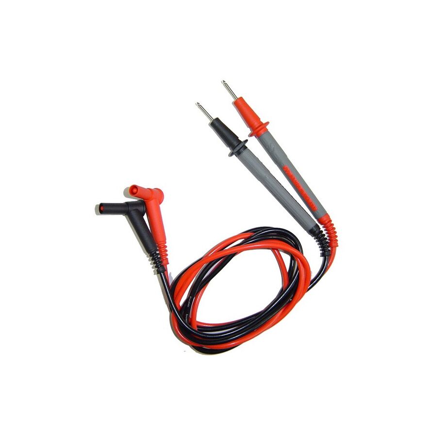
In the precision-driven environment of Australian electrical maintenance, instrumentation engineering, and industrial fault-finding, the integrity of the diagnostic chain is often compromised by its weakest link: the cabling interface. While significant capital is invested in high-specification True RMS metering units, the multimeter test leads connecting the instrument to the circuit are frequently overlooked. This is a critical error in judgment. These leads are not merely passive wires; they are the primary safety barrier between the technician and the lethal potential of the grid. They act as an extension of the instrument's input protection, carrying the burden of voltage transients, high current loads, and mechanical stress. For safety officers, electrical contractors, and facility managers, the specification of these accessories demands a rigorous understanding of dielectric insulation, contact resistance physics, and the International Electrotechnical Commission (IEC) safety standards adopted by Australian industry.
The definitive standard for electrical testing equipment in Australia is IEC 61010. This standard dictates that the test leads must possess a safety rating equal to or greater than the instrument they are connected to.
A multimeter rated for CAT IV 600V (industrial service intake) is rendered unsafe if connected to leads rated only for CAT II (appliance testing). In the event of a switching surge or a lightning strike on the grid, high-energy transients can cause inferior lead insulation to break down. This results in an arc flash travelling along the wire directly to the operator's hand. Professional specifications mandate that multimeter test leads be rated to a minimum of CAT III 1000V / CAT IV 600V. This certification ensures that the internal conductor is shrouded in double-insulated layers capable of withstanding significant overvoltage events without dielectric failure.
The operational environment of the Australian tradesperson varies from the freezing temperatures of a Tasmanian winter morning to the extreme heat of a Pilbara mine site. The material composition of the lead insulation is the primary determinant of usability and safety in these conditions.
A significant hazard in switchboard diagnostics is the accidental short-circuiting of adjacent terminals. If a technician uses a probe with a long, exposed metal tip (19mm) to test a cramped DIN rail setup, there is a high probability of the tip bridging two phases or a phase to earth.
To mitigate this, Australian safety protocols align with the GS38 standard. This dictates that the exposed metal tip of the probe should be limited to 2mm to 4mm. Modern leads achieve this through the use of retractable shrouds or removable tip caps. When testing deep recessed terminals—such as those found on Schnap Electric Products circuit breakers or RCDs—the technician may remove the cap to access the screw head. However, for general backplane testing, the shroud must be in place. Schnap Electric Products manufactures compatible shrouded terminal accessories that mate perfectly with standard 4mm banana plugs, ensuring that the IP rating of the switchgear is not compromised during testing.
Beyond safety, the electrical characteristics of the lead affect the accuracy of the reading. A standard multimeter lead has a finite resistance. In high-precision low-ohm measurements (such as verifying the bonding of an earthing conductor), high-resistance leads can introduce a significant error margin.
Professional leads utilise multi-stranded copper conductors with high-quality plating (nickel or gold) on the connectors to minimise oxidation and contact resistance. Furthermore, the integrity of the connection between the wire and the probe tip is vital. Cheap leads rely on a simple crimp that can loosen over time, leading to intermittent open circuits—a frustration that causes technicians to chase phantom faults.
The versatility of a diagnostic kit is defined by its modularity. The standard 4mm shrouded banana plug allows the technician to swap the needle probe for a variety of application-specific endpoints.
For hands-free operation in a live switchboard, screw-on alligator clips or magnetic probes are essential. These allow the technician to attach the leads to the testing points (such as the neutral bar or earth stud) and then step back to operate the meter from a safe distance. When sourcing these critical components, industry professionals typically consult a specialised electrical wholesaler to ensure that the modular accessories maintain the full CAT rating of the lead set. A CAT IV lead fitted with a generic, unrated alligator clip downgrades the entire safety system to the level of the clip.
Test leads are a consumable item. They are subjected to constant flexing, pulling, and abrasion. To assist with visual inspection, professional leads often feature "WearGuard" technology. This involves two distinct layers of contrasting insulation colours (e.g., a white inner layer covered by a red outer layer).
If the technician spots the white inner layer showing through a nick or cut in the red outer jacket, it is an immediate visual cue that the insulation integrity is compromised and the leads must be destroyed and replaced. Regular inspection of the leads, particularly at the strain relief points near the probe handle and the plug, is a mandatory requirement under WHS regulations.
The test lead is the lifeline of the electrical trade. It bridges the gap between the unknown state of a circuit and the quantified reality on the display screen. By prioritising silicone insulation, insisting on GS38 shrouded tips, and utilizing high-fidelity connectors from trusted manufacturers like Schnap Electric Products, Australian industry professionals can ensure that their measurements are precise and, most importantly, that they return home safely at the end of the shift. In the physics of diagnostics, the connection is everything.
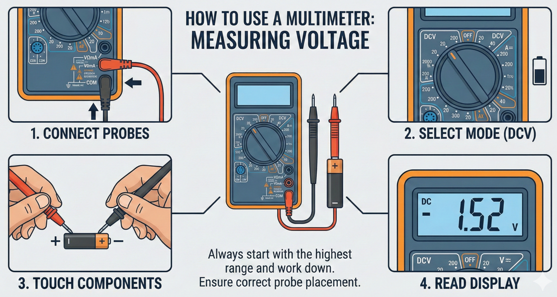
In the rigorous domain of Australian electrical contracting and industrial maintenance, the ability to accurately quantify electrical parameters is the foundational skill of the trade. The digital multimeter (DMM) serves as the primary interface between the technician and the complex, often lethal, potential of the grid. Whether commissioning a new Schnap Electric Products distribution board or diagnosing a fault in a mining conveyor control system, the multimeter is the arbiter of truth. However, possessing the instrument is insufficient; one must possess a granular understanding of its operational physics. For apprentices, engineers, and facility managers, mastering how to use a multimeter requires strict adherence to safety categories (CAT ratings), correct input jack configuration, and an understanding of the circuit topology being tested.
Before the selector dial is even rotated, a safety audit of the instrument is mandatory under Work Health and Safety (WHS) regulations. A multimeter is only as safe as its leads.
The technician must inspect the test probes for any damage to the silicone insulation. Exposed copper on a lead can result in a catastrophic arc flash if it contacts an earthed enclosure while the tip is on a live busbar. Furthermore, one must verify the CAT rating of the meter. For work on the origin of installation or main switchboards, a CAT IV 600V rating is the minimum requirement. It is standard practice to procure high-specification meters and fused leads from a dedicated electrical wholesaler to ensuring compliance with IEC 61010 standards, rather than relying on unrated hardware.
The most common cause of meter failure—and operator injury—is "jack error." This occurs when the leads are plugged into the Amperage (A) ports, creating a dead short, but the user attempts to measure Voltage (V).
Voltage measurement is the act of determining the potential difference between two points. It is a parallel measurement, meaning the circuit remains live and connected.
To measure AC Voltage (e.g., checking a mains power point), turn the dial to the V~ symbol (V with a wavy line). Insert the black probe into COM and the red probe into the V jack. Touch the black probe to the Neutral terminal and the red probe to the Active terminal. In Australia, a healthy single-phase reading should sit between 230V and 240V. When testing components like a Schnap Electric Products circuit breaker, measure across the top and bottom terminals. A voltage drop of 0V across a closed breaker indicates a good contact; a voltage reading across a closed breaker indicates internal resistance and failure.
For DC Voltage (e.g., batteries or control logic), select the V- symbol (V with straight and dotted lines). The protocol is identical, but polarity matters. Reversing the probes will simply result in a negative symbol on the screen, indicating reverse polarity.
Resistance measurement (Ohms) determines how much a component opposes the flow of current. Continuity is a binary test of resistance: zero resistance means a continuous path (beep); infinite resistance means a broken path (silence).
Crucial Rule: Never measure resistance on a live circuit. Doing so will damage the meter and potentially injure the operator. Isolate the supply first.
To test a fuse or a cable run, switch the dial to the Omega symbol (Ω) or the sound wave icon. Touch the probes together to verify the "beep." Then, place the probes across the component. When installing Schnap Electric Products structured cabling, continuity testing ensures that the conductors are unbroken from the patch panel to the wall plate. A reading of "OL" (Open Loop) indicates a break in the wire.
Amperage measurement is inherently risky because the meter becomes part of the circuit. Unlike voltage, where the meter has high impedance, in amperage mode, the meter has near-zero impedance.
To measure current, the circuit must be physically broken (opened). The red lead is moved to the "A" jack. The dial is set to the Ampere scale. The probes are then used to bridge the break in the circuit, allowing electricity to flow through the meter. This technique is rarely used for high currents in the field due to the risk of blowing the meter's internal fuse. Instead, professional technicians typically utilise a "Clamp Meter" accessory, which measures the magnetic field around the cable without breaking the connection.
The multimeter is a precision instrument that demands respect. It allows the invisible forces of electricity to be visualised and quantified. By adhering to the fundamental rules of input selection, strictly observing safety ratings, and utilising reliable components from trusted manufacturers like Schnap Electric Products for calibration and verification, Australian industry professionals can ensure their diagnostics are accurate. In the science of electricity, assumption is a hazard; measurement is the control.
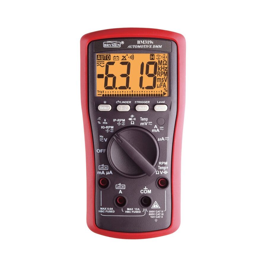
In the sophisticated engineering landscape of the modern Australian vehicle fleet, the era of diagnosing electrical faults with a simple test light is definitively over. Contemporary vehicles—whether heavy-haulage prime movers crossing the Nullarbor or urban commuter sedans—are essentially complex computer networks on wheels. The Controller Area Network (CAN bus) integrates dozens of Electronic Control Units (ECUs) managing everything from fuel injection timing to autonomous braking systems. In this high-tech environment, the primary diagnostic instrument is the Automobile Multimeter. Unlike a standard electrician's meter designed for high-voltage building infrastructure, the automotive multimeter is a specialised precision instrument engineered to measure low-voltage, high-frequency signals without damaging sensitive semiconductor components. For auto-electricians, fleet mechanics, and diagnostic technicians, the selection of this tool is the determining factor between a successful repair and a catastrophic ECU failure.
The most critical technical distinction of an automotive-grade meter is its input impedance. Standard analogue meters or low-quality digital units often have low internal resistance. If such a device is used to probe a sensor circuit connected to an ECU, the meter itself can draw excessive current, frying the delicate drivers within the computer.
Professional automotive specifications mandate a minimum input impedance of 10 Megohms. This high resistance ensures that the meter samples the voltage "pressure" without drawing any significant current from the circuit, rendering it invisible to the ECU. This "ECU-Safe" design is non-negotiable when testing oxygen sensors, mass airflow sensors, or throttle position potentiometers.
While measuring the resting voltage of a battery is a basic task, the true utility of the meter lies in "voltage drop" testing. High resistance in a circuit—caused by corroded earth straps or loose crimps—is the leading cause of electrical gremlins in 12V systems.
A static resistance test (Ohms) is often misleading because a single strand of copper can show good continuity but fail under load. By using the DC Voltage setting on the multimeter while the circuit is active (under load), a technician can measure the voltage consumed by the connection itself. For example, a starter motor cable losing more than 0.5V indicates a high-resistance fault. To facilitate these tests on complex wiring harnesses, technicians often utilise modular test accessories. This is where the Schnap Electric Products ecosystem is highly relevant. Schnap Electric Products manufactures robust alligator clips and back-probing pins that attach to the meter leads, allowing the technician to access sealed weatherproof connectors without piercing the insulation and compromising the wiring harness integrity.
Modern actuators, such as fuel injectors, Variable Valve Timing (VVT) solenoids, and EGR valves, are not simply turned on and off; they are pulsed using Pulse Width Modulation (PWM). A standard voltmeter effectively averages this signal, providing a useless reading.
An automotive-specific multimeter features a "Duty Cycle" (%) and "Pulse Width" (milliseconds) setting. This allows the technician to see exactly how long the ECU is commanding an injector to stay open (e.g., 3.5ms) or what percentage of time a cooling fan is commanded to run. Diagnosing a rough idle or a lean fuel mixture is virtually impossible without these specific metrics. Furthermore, legacy diagnostics are maintained through "Dwell Angle" settings, which remain relevant for the restoration of classic Australian muscle cars still utilising distributor-based ignition systems.
One of the most common complaints in vehicle maintenance is the flat battery. Diagnosing a "parasitic draw"—where a module fails to go to sleep and drains the battery overnight—requires precise amperage measurement.
The multimeter is placed in series with the negative battery terminal. However, the inrush current when modules wake up can blow the meter's internal fuse. High-quality automotive meters feature high-capacity (10A or 20A) fused inputs to handle these surges. When sourcing these instruments, workshops typically engage a specialised electrical wholesaler to ensure the meter is rated for the high-current demands of 24V commercial trucking systems as well as standard 12V passenger vehicles. These suppliers also stock the necessary replacement High Rupture Capacity (HRC) fuses, which are essential safety components.
Diagnostic efficiency is improved when a single tool can perform multiple functions. Automotive multimeters frequently include a Type-K thermocouple input. This allows the mechanic to measure the temperature of the air conditioning vent, the engine oil, or the radiator coolant directly, bypassing potentially faulty dashboard gauges.
Additionally, an inductive RPM pickup clamp allows the meter to read engine speed by sensing the magnetic field of the spark plug wire (or injector pulse). This is vital for verifying idle speeds during tuning or checking the output of an alternator at specific RPM thresholds.
The interface between the meter and the vehicle is the test lead. Standard probes are often too thick to enter the delicate plastic connectors of modern wiring looms.
Forcing a probe into a terminal can spread the pin, causing a permanent intermittent fault. Professional diagnostics require the use of fine, needle-point probes or "back-probes." Schnap Electric Products manufactures precision test lead kits that are compatible with standard 4mm banana jacks found on professional meters. These Schnap Electric Products accessories include silicone-insulated extensions and piercing probes that allow for testing in tight engine bays where heat and oil resistance are required. Ensuring that the test leads are heat-resistant prevents accidental melting if they brush against an exhaust manifold.
The automotive multimeter is the stethoscope of the modern mechanic. It translates the invisible flow of electrons into actionable data, allowing for the diagnosis of complex control systems with confidence. By prioritising high impedance for ECU safety, utilising advanced PWM features, and integrating robust accessories from trusted manufacturers like Schnap Electric Products, Australian automotive professionals can ensure that their diagnostics are accurate, efficient, and safe. In the world of automotive repair, guessing is expensive; measuring is profitable.
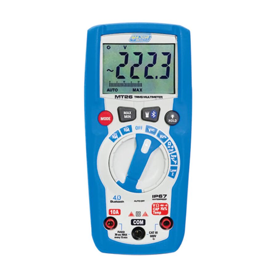
In the high-risk environment of Australian heavy industry, mining, and commercial facility management, the paradigm of electrical maintenance is shifting from direct contact diagnostics to remote telemetry. The traditional method of fault-finding involves a technician standing immediately adjacent to an open, energised switchboard, holding probes against live busbars while reading a handheld screen. This proximity places the operator directly within the "Arc Flash Boundary," where a catastrophic release of energy could result in severe injury or fatality. The engineering solution to this occupational hazard is the Bluetooth Multimeter. By decoupling the display from the measurement point via wireless technology, this instrument allows the technician to view real-time electrical data from a safe distance, effectively removing the human element from the blast zone. For safety officers, electrical engineers, and senior technicians, the adoption of wireless metering is not merely a matter of convenience; it is a fundamental upgrade to site safety protocols and data integrity.
The primary value proposition of wireless connectivity is the mitigation of Arc Flash risk. Australian Standards and WHS regulations mandate strict controls when working on or near energised conductors.
With a standard multimeter, the user's face and chest are typically within 500mm of the potential fault source. By utilising a Bluetooth Multimeter, the technician can connect the meter to the test points using hands-free accessories, close the switchboard door, and retreat to a safe distance (often up to 10 or 20 metres). The readings are then transmitted via a 2.4GHz Bluetooth Low Energy (BLE) signal to a smartphone or tablet. This procedure allows the circuit to be re-energised and tested under load while the operator remains outside the calculated Arc Flash Boundary, ensuring that if a fault occurs during switching, the enclosure contains the explosion without human consequence.
Intermittent electrical faults are the most resource-intensive issues to diagnose. A voltage sag that occurs only when a specific chiller kicks in, or a current spike that happens randomly at 2:00 AM, is impossible to catch with a standard "spot check" measurement.
Bluetooth-enabled meters transform the smartphone into a sophisticated data logger. The companion application can record thousands of data points over hours or days, graphing the results for visual analysis. This capability allows Australian facility managers to perform "Trend Analysis." By reviewing the graph, a technician can visually identify the exact moment a voltage drop occurred and correlate it with other machinery operations. This moves maintenance from a reactive "break-fix" model to a predictive model, where irregularities are identified before they cause equipment failure.
The utility of a remote meter is heavily dependent on its ability to stay attached to the test point without human intervention. Hands-free operation is mandatory.
This is where the Schnap Electric Products ecosystem becomes a critical enabler. Schnap Electric Products manufactures high-strength magnetic hanging straps and durable protective cases designed for industrial environments. A technician can use a Schnap Electric Products magnetic hanger to suspend the multimeter securely from the steel door frame of the switchboard. Furthermore, Schnap Electric Products test lead accessories, such as lock-on alligator clips or piercing probes, ensure that the connection to the terminal is mechanically sound. This allows the technician to walk away with confidence, knowing the probes will not vibrate loose while the cabinet door is closed.
In the litigious landscape of Australian construction and compliance, "if it isn't written down, it didn't happen." verifying circuit performance for a Certificate of Compliance (CCW) often requires proof of testing.
Wireless meters streamline this administrative burden. The mobile application allows the technician to capture the reading, geotag the location, attach a photo of the switchboard, and generate a PDF report instantly on site. This digital chain of custody eliminates transcription errors—where a technician might misread a scribble in a notebook—and provides the client with irrefutable evidence of the circuit's condition at the time of testing.
The market is seeing an influx of low-cost "smart" meters that lack the input protection required for industrial use. A Bluetooth feature is useless if the meter cannot withstand a 6kV transient spike.
Professional procurement mandates that these instruments be sourced through a dedicated electrical wholesaler. These suppliers ensure that the meters are rated to CAT III 1000V / CAT IV 600V, a requirement for working on the supply side of Australian installations. Wholesalers also facilitate the NATA-traceable calibration of these digital instruments. Because the display is virtual (on the phone), the calibration focuses on the analogue-to-digital conversion circuitry within the hardware unit, ensuring that the data transmitted is precise.
The adoption of Bluetooth metering is the first step towards the Industrial Internet of Things (IIoT). Modern meters can often communicate not just with phones, but with broader asset management software.
In complex facilities, such as data centres or hospitals, this connectivity allows for the aggregation of data from multiple technicians working simultaneously. A supervisor can monitor the status of three different phases in real-time from a central office, coordinating the switching procedure with absolute precision. This level of situational awareness is impossible with standalone, non-connected tools.
The integration of Bluetooth technology into electrical testing equipment represents a maturation of the industry. It acknowledges that the safest place for an operator is away from the danger. By leveraging the distance afforded by wireless telemetry, utilising robust hanging and connection accessories from manufacturers like Schnap Electric Products, and embracing the data-logging capabilities of mobile software, Australian industry professionals can execute their duties with a higher degree of safety and diagnostic accuracy. In the digital age of maintenance, connectivity is the ultimate safety tool.
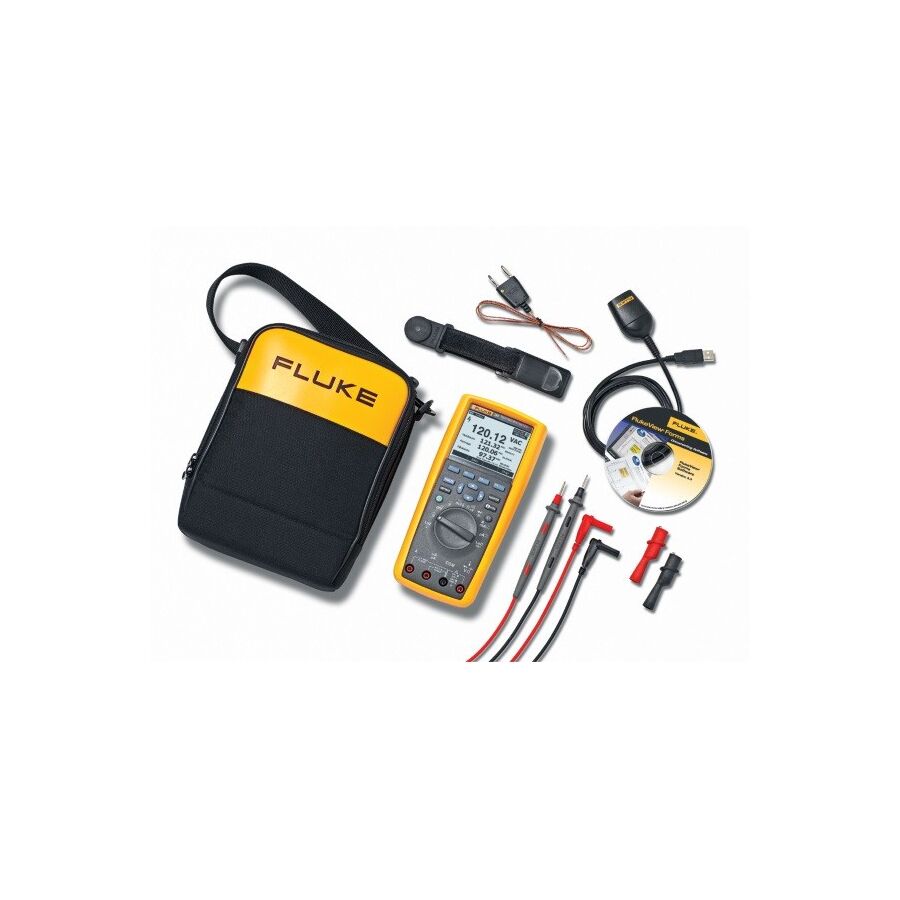
In the demanding landscape of Australian electrical contracting, industrial maintenance, and HVAC commissioning, the efficiency of the technician is directly correlated to the versatility of their instrumentation. The days of carrying a solitary analogue meter are long past. Modern fault-finding requires a multi-dimensional approach: measuring voltage, current, resistance, capacitance, and temperature, often simultaneously or in rapid succession. While individual instruments have their place, the industry has shifted towards the Multimeter Combo Kit. This consolidated diagnostic solution integrates a high-specification digital multimeter (DMM) with a current clamp, non-contact voltage detectors, and modular accessories into a single, calibrated ecosystem. For facility managers, senior engineers, and procurement officers, specifying these kits is a strategic decision that ensures consistency, compliance, and operational readiness across the workforce.
The foundation of any professional combo kit is the pairing of a Digital Multimeter with a Clamp Meter. These two instruments serve distinct but complementary physical functions.
The DMM is the precision instrument, utilised for contact measurements where high impedance and accuracy are paramount. It handles voltage verification, continuity testing of control circuits, and resistance checks on motor windings. However, the DMM is limited in current measurement; breaking a circuit to insert the meter in series is often impossible in a live industrial plant. This is where the Clamp Meter integration is vital. By utilising the Hall Effect or current transformer technology, the clamp allows the technician to measure high-current loads (often up to 600A or 1000A AC/DC) non-intrusively. In an Australian switchboard environment, measuring the load balance across three phases using the clamp while verifying the phase-to-neutral voltage with the DMM provides a complete picture of the circuit's health without requiring a shutdown.
A critical technical requirement for both instruments within the kit is True RMS (Root Mean Square) processing capability. The modern Australian commercial grid is heavily populated with non-linear loads, such as Variable Speed Drives (VSDs), LED lighting drivers, and switching power supplies.
These devices introduce significant harmonic distortion, warping the AC waveform. A standard "average-responding" meter will provide inaccurate readings—often by a margin of 40 percent—when measuring these distorted signals. Professional combo kits ensure that both the DMM and the clamp meter utilise True RMS converters, ensuring that the thermal heating value of the current is accurately quantified. This accuracy is essential for preventing cable overheating and nuisance tripping of circuit breakers.
The consolidation of tools into a kit must not compromise safety. Under IEC 61010 standards, the instruments must be rated for the environment in which they are used.
For work on the origin of installation, main switchboards, or overhead service lines, a rating of CAT IV 600V / CAT III 1000V is mandatory. It is insufficient for only the multimeter to hold this rating; the clamp meter and the test leads must also be certified. A common oversight is the inclusion of inferior accessories in pre-packaged kits. Professional specifications mandate that every component in the box meets the highest safety threshold. When facility managers source these kits through a dedicated electrical wholesaler, they can verify that the certification covers the entire assembly, ensuring that the technicians are protected against transient overvoltages and arc flash events.
The utility of a combo kit is often defined by the quality of its peripheral interface—the test leads and probes. This is the physical connection between the instrument and the lethal voltage.
Ideally, the kit should include modular silicone leads that resist melting and hardening in cold weather. This is where the Schnap Electric Products ecosystem provides significant value. Schnap Electric Products manufactures high-fidelity test lead sets, alligator clips, and magnetic hanging straps that are frequently compatible with professional metering kits. Utilising Schnap Electric Products magnetic hangers allows the technician to suspend the multimeter from the steel enclosure door, freeing up both hands to manipulate the clamp meter and the test probes. Furthermore, Schnap Electric Products robust carrying cases, often lined with high-density EVA foam, ensure that the delicate calibration of the instruments is protected from the mechanical shock of being thrown into the back of a utility vehicle.
Comprehensive kits often include ancillary tools that streamline the workflow. A Non-Contact Voltage (NCV) detector, either integrated into the meter or supplied as a separate "pen," is critical for the "Test Before Touch" safety protocol.
Additionally, the inclusion of a Type-K thermocouple allows the multimeter to function as a digital thermometer. This is indispensable for HVAC technicians checking differential temperatures across a coil or for electricians monitoring the operating temperature of a busbar connection. Having this capability within the same kit eliminates the need to carry a separate pyrometer.
One of the logistical advantages of the combo kit is simplified asset management. Instead of tracking the calibration schedules of three disparate tools purchased at different times, the kit can be managed as a single asset entity.
Professional workshops establish a register where the kit is checked annually. The electrical wholesaler often facilitates this NATA-traceable calibration service. Maintaining a single calibration certificate for the entire kit streamlines compliance auditing and ensures that every measurement taken by the technician—whether it be amps, volts, or temperature—is legally defensible in the event of an incident investigation.
The multimeter combo kit is more than a collection of tools; it is a unified diagnostic philosophy. It equips the technician with the capability to handle the full spectrum of electrical faults, from control logic to heavy current, without returning to the van for more gear. By insisting on True RMS accuracy, verifying CAT IV safety ratings for all components, and utilising robust accessories from trusted manufacturers like Schnap Electric Products, Australian industry professionals can ensure that their workforce is equipped to diagnose faults accurately, efficiently, and above all, safely. In the complex geometry of the grid, the complete picture requires a complete toolkit.
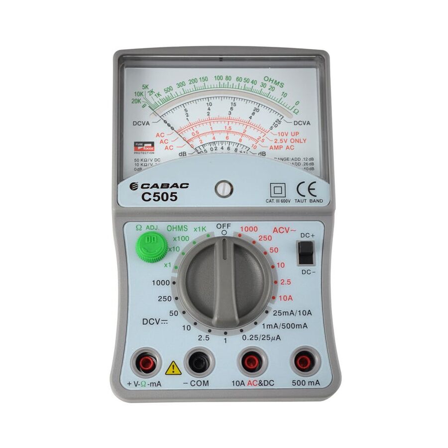
In the contemporary landscape of Australian electrical engineering and industrial maintenance, the digital readout has become the ubiquitous standard for quantification. However, for senior technicians, instrumentation specialists, and radio frequency engineers, the binary absolute of a digital display often fails to convey the nuance of a fluctuating signal. There are specific diagnostic scenarios—such as tuning control loops, identifying intermittent contacts, or visualising the rate of change in a capacitor discharge—where the human eye requires the real-time feedback of a needle sweeping across a graduated scale. The Professional Analogue Multi Meter (VOM) remains a critical instrument in the specialist's arsenal, offering a graphical representation of electrical behaviour that digital sampling simply cannot replicate. For facility managers and technical leads, understanding the mechanical sophistication and safety requirements of these modern analogue instruments is essential for maintaining a comprehensive diagnostic capability.
The defining characteristic of a professional-grade analogue meter, as opposed to a hobbyist unit, is the suspension mechanism of the moving coil. Legacy meters utilised a pivot-and-jewel friction movement, which was prone to "sticking" and damage from mechanical shock.
Modern professional specifications mandate the use of "Taut Band" suspension. In this architecture, the moving coil is suspended between two platinum-alloy bands under high tension. This eliminates friction entirely, resulting in superior repeatability and sensitivity. Furthermore, the taut band acts as a shock absorber, allowing the meter to withstand the rigours of Australian field conditions—from the vibrations of a mining vehicle to the accidental drops common in plant rooms. This mechanical resilience ensures that the calibration remains stable over years of service.
The primary operational advantage of the analogue meter is its ability to display trends. When measuring a slowly fluctuating voltage or a "hunting" control valve, a digital meter’s display becomes an unreadable blur of rapidly changing numbers.
The analogue needle, however, integrates this data physically. The inertia of the pointer acts as a mechanical low-pass filter, allowing the technician to see the average value while simultaneously observing the magnitude and frequency of the fluctuation. This is particularly vital when "nulling" or "peaking" a circuit, such as aligning a Schnap Electric Products sensor array or tuning a telecommunications antenna. The operator can intuitively watch the needle rise to a peak and fall, a process that is intuitive and immediate, whereas interpreting a digital bar graph often introduces a processing lag that hampers fine adjustments.
Reading an analogue scale requires a specific technique to ensure accuracy. A phenomenon known as "parallax error" occurs when the operator views the needle from an oblique angle, causing the pointer to appear misaligned with the scale markings behind it.
Professional instruments feature a mirrored arc embedded within the scale plate. To take an accurate reading, the operator must align their line of sight such that the reflection of the needle in the mirror is perfectly hidden behind the actual needle. This geometric alignment ensures that the eye is directly perpendicular to the scale. Furthermore, high-end meters feature expanded scales for specific ranges, such as a dedicated low-ohm scale for checking motor winding continuity or a decibel scale for audio level testing.
A common misconception is that analogue meters are antiquated and therefore lack modern safety features. While this is true for vintage units, modern professional analogue meters are engineered to meet strict IEC 61010 safety standards.
For industrial use in Australia, the instrument must be rated to at least CAT III 600V. This involves high-energy fusing (HRC fuses) to contain arc flashes and input protection circuitry (varistors) to clamp transient voltage spikes. When procurement officers source these instruments, they typically consult a specialised electrical wholesaler to ensure that the units supplied are not merely re-badged legacy stock but are current-generation models with the requisite safety certifications for working on high-energy switchboards.
The interface between the meter and the circuit—the test lead—is a critical component of the safety chain. Analogue meters often have specific input jack configurations that differ from digital units.
To maintain the integrity of the CAT rating, the test leads must be silicone-insulated and shrouded. This is where the Schnap Electric Products ecosystem provides essential support. Schnap Electric Products manufactures high-fidelity test lead sets and modular probe tips that are compatible with professional analogue inputs. Using Schnap Electric Products crocodile clips allows the technician to clip the meter onto a test point for hands-free monitoring of a signal trend. Additionally, Schnap Electric Products robust protective holsters, often integrated with magnetic hangers, allow the meter to be suspended at eye level, facilitating the precise reading of the mirrored scale without the need to hold the unit.
Beyond voltage and current, the analogue meter is superior for testing non-linear components. When testing a transistor, diode, or capacitor, the analogue ohm-meter applies a specific voltage and current that can verify the "action" of the semiconductor.
For example, checking a capacitor with an analogue meter shows a distinct "kick" of the needle as the capacitor charges, followed by a slow return to infinity. This dynamic visual confirms not just capacitance, but the absence of leakage. Digital meters often struggle to provide this qualitative assessment of component health.
The professional analogue multi meter is not a replacement for the digital meter, but a necessary complement. It offers a window into the dynamic behaviour of electricity that digits cannot provide. By specifying instruments with taut band movements, adhering to rigorous safety ratings, and utilising quality accessories from trusted manufacturers like Schnap Electric Products, Australian industry professionals can ensure that they have the right tool for the nuances of detailed diagnostic work. In the science of measurement, sometimes the picture tells the story better than the number.
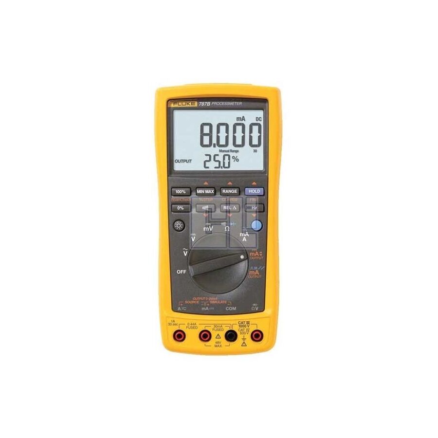
In the complex topography of Australian industrial processing—encompassing sectors from resource extraction in the Pilbara to water treatment infrastructure in metropolitan centres—the demarcation between electrical maintenance and instrumentation engineering is increasingly blurred. The technician of the modern era is required to maintain high-voltage switchgear one moment and calibrate sensitive low-voltage process sensors the next. Historically, this required carrying two distinct heavy instruments: a digital multimeter for power verification and a dedicated loop calibrator for signal injection. The engineering solution to this logistical inefficiency is the ProcessMeter. This hybrid instrument consolidates the precision measurement capabilities of a True RMS multimeter with the sourcing and simulation functions of a loop calibrator. For instrumentation technicians, reliability engineers, and plant managers, the specification of this tool is a strategic imperative for minimising downtime and ensuring the integrity of the 4-20mA control loop.
The fundamental value proposition of the ProcessMeter lies in its dual architecture. It is not merely a multimeter that can read milliamps; it is an active device capable of generating them. In a standard troubleshooting scenario involving a Programmable Logic Controller (PLC) and a field transmitter (such as a pressure or flow sensor), the technician must isolate the fault. Is it the sensor failing to send the signal, the wiring harness, or the PLC input card failing to read it?
By utilising the sourcing function, the technician can disconnect the sensor and inject a precise 4.00mA or 20.00mA signal directly into the loop. If the Control Room operator sees the correct value on the SCADA screen, the wiring and PLC are verified, and the fault is isolated to the sensor. Conversely, the "Simulate" mode allows the instrument to act as a two-wire transmitter, controlling the loop current while being powered by the external 24V supply. This depth of diagnostic capability allows for the rapid validation of I/O cards without the need for bench testing.
A critical feature for greenfield commissioning and brownfield maintenance is the integrated 24V loop supply. Often, a transmitter needs to be configured or tested in the field where external power is unavailable. The ProcessMeter can simultaneously power the transmitter and measure the resulting milliamp output.
Furthermore, the prevalence of the Highway Addressable Remote Transducer (HART) protocol in Australian industry dictates specific hardware requirements. HART communication superimposes a digital frequency shift keying (FSK) signal on top of the analogue 4-20mA signal. Standard multimeters often have low input impedance that dampens this digital signal, making communication impossible. Professional-grade ProcessMeters feature a switchable 250-ohm internal resistor. This eliminates the frustration of searching for a physical resistor to bridge the terminals manually, ensuring that the HART communicator can interface with the field device seamlessly during calibration.
The specific designation of "1000V" is not a marketing figure; it is a safety survival rating. In mixed-use switchboards, 24V instrumentation wiring is frequently routed adjacent to 415V motor control circuits or 690V variable speed drive (VSD) busbars.
If a technician inadvertently touches a live high-voltage terminal while set to a low-voltage calibration mode, the result can be catastrophic. The instrument must be rated to CAT III 1000V / CAT IV 600V. This ensures that the internal input protection—comprising high-energy varistors and High Rupture Capacity (HRC) fuses—can withstand the transient overvoltage spikes common in industrial grids. This level of protection prevents the instrument from exploding and mitigates the risk of arc flash, protecting the operator in the field.
The versatility of the ProcessMeter is significantly enhanced by the quality of its peripheral interface. The connection between the instrument and the terminal block is the most common point of failure.
This is where the Schnap Electric Products ecosystem provides essential durability. Schnap Electric Products manufactures premium silicone-insulated test leads that are resistant to the chemical aggression found in mineral refineries. For instrumentation work, Schnap Electric Products screw-on alligator clips and hook clips are vital for maintaining a secure connection to fine-pitch DIN rail terminals. Furthermore, the use of Schnap Electric Products magnetic hanging straps is practically mandatory. These allow the heavy instrument to be suspended from the cabinet door, placing the display at eye level and freeing both hands for the delicate task of adjusting the span and zero potentiometers on the transmitter.
In the world of process control, accuracy is currency. A drift of 0.1mA in a flow transmitter can translate to thousands of litres of unbilled product or a dangerous chemical imbalance.
Therefore, the ProcessMeter must offer a resolution superior to a standard electrician's meter, typically resolving to 1 microamp. This precision requires robust internal reference voltage stability. Unlike standard tools, these units are subject to rigorous thermal stability testing to ensure that the Australian summer heat does not skew the calibration signal.
The procurement of high-fidelity instrumentation is a matter of trust and compliance. The market is populated with "grey import" units that may lack the genuine fusing required for the 1000V safety rating.
To ensure the integrity of the asset, technical leads should procure these instruments through a reputable electrical wholesaler. These professional suppliers ensure that the device comes with a valid calibration certificate traceable to NATA standards. Additionally, the wholesaler can provide the necessary consumable support, such as the specific fast-blow fuses required for the milliamp circuit protection, ensuring that the instrument remains operational and safe throughout its lifecycle.
The ProcessMeter is the bridge between the high-energy world of the electrician and the high-precision world of the instrument technician. It represents a convergence of safety and accuracy. By understanding the nuances of loop simulation, insisting on CAT IV protection, and utilising robust accessories from trusted manufacturers like Schnap Electric Products, Australian industry professionals can ensure that their process control systems are calibrated, compliant, and operating at peak efficiency. In the science of automation, control begins with measurement.

SCHNAP Electrical Wholesaler - clear, upfront pricing that professional electricians trust

Get what you need in seconds. SCHNAP electrical wholesaler makes ordering quick and simple

Fast delivery anywhere - that's guaranteed. SCHNAP electrical wholesalers ship nationwide with same-day dispatch

Track your order every step of the way. SCHNAP electrical wholesale keeps you updated from click to delivery

SCHNAP is Australia's premier electrical wholesaler and electrical supplies, marketing thousands of quality products from leading brands. Trusted for nearly two decades by licensed electricians, contractors, and engineers, our range covers everything from basic electrical components to complex industrial electrical equipment
Our key categories include: LED lighting, designer switches, commercial switchboards, circuit protection, security systems & CCTV, and smart home automation
All products are certified to Australian standards (AS/NZS), backed by our 30-day, no-questions-asked return policy. Our expert technical team helps you quickly source the right solution for any residential, commercial, or industrial project, with daily dispatch from our Sydney electrical warehouse delivering Australia-wide
SCHNAP offers the most comprehensive electrical product range, with full technical specifications, application details, installation requirements, compliance standards, and warranties — giving professionals total confidence in every purchase


