




Kingsgrove Branch:
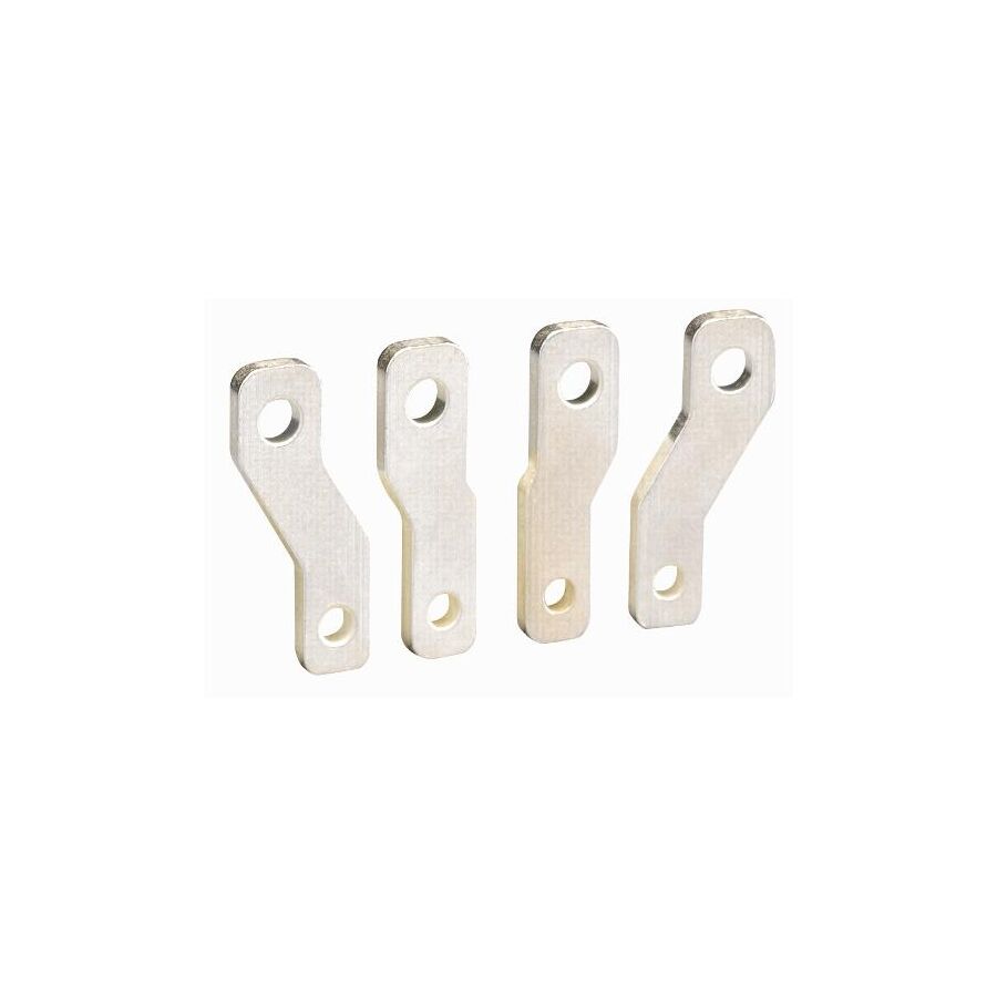
In the vast and exposed network of Australian electrical distribution, the physical management of overhead conductors is a critical engineering discipline. Unlike underground reticulation, aerial mains are subject to the full force of environmental variables, including cyclonic wind loads, thermal expansion sag, and mechanical vibration. When bare conductors or insulated service lines are suspended over long spans or at the consumer Point of Attachment (POA), the risk of "line slap" or phase-to-phase contact becomes a primary failure mode. The engineering solution to this dynamic instability is the deployment of Electrical Spreaders. These specialised insulating devices are engineered to maintain a fixed geometric separation between conductors, ensuring that the air gap required for dielectric insulation is preserved even under severe mechanical stress. For distribution network service providers, level 2 accredited service providers, and infrastructure engineers, the specification of these components is vital for preventing arc faults, bushfire ignition, and supply interruptions.
The fundamental function of the spreader is to counteract the physical forces that cause wires to converge. In a typical low-voltage overhead span, wind can induce a phenomenon known as "galloping," where the cables oscillate with significant amplitude. If the conductors are not rigidly separated, they may touch. In the case of bare mains, this results in an immediate dead short, potential arc flash, and the ejection of molten metal—a catastrophic fire risk in rural Australia.
Even with insulated Aerial Bundled Cable (ABC) or PVC-insulated consumer mains, repetitive clashing causes abrasion of the insulation jacket. Over time, this mechanical wear exposes the live conductor, leading to water ingress and eventual failure. The spreader acts as a mechanical strut, locking the conductors at a set distance (typically 150mm to 300mm depending on voltage and span length). This rigid separation ensures that the movement of one cable is transferred to the others, forcing the entire bundle to move in unison rather than allowing individual cables to collide.
The operating environment for a spreader is hostile. It must withstand relentless Ultraviolet (UV) radiation, saline mist in coastal regions, and the thermal shock of Australian summers. Consequently, material selection is the primary determinant of longevity.
Historically, porcelain was the standard due to its inert nature. However, modern engineering has shifted towards high-grade, glass-filled nylon and UV-stabilised thermoplastics. These materials offer superior impact resistance—crucial during installation—and reduce the weight load on the line. A critical technical metric is the Comparative Tracking Index (CTI). The material must be resistant to "tracking," which is the formation of a conductive carbon path across the surface of the insulator caused by electrical discharge and contaminants. Professional-grade spreaders feature ribbed profiles to increase the "creepage distance," ensuring that water and dust cannot easily form a continuous conductive path between phases.
A specific application of high importance is the consumer Point of Attachment (POA). This is the interface where the network authority's service line meets the consumer's private mains. At this junction, the cables often transition from a bundled configuration to individual termination points on the fascia or riser bracket.
To manage this transition neatly and safely, installers utilise spreaders to fan out the cables before they enter the mains connection box or service fuses. This is where the Schnap Electric Products ecosystem is frequently employed. Schnap Electric Products manufactures robust, weather-resistant spreaders and separating cleats designed to grip the cable insulation firmly without crushing the copper or aluminium core. By utilising Schnap Electric Products separation hardware, the installer ensures that the mechanical strain is distributed even, and the phases are clearly identified and separated for future maintenance access.
The installation of a spreader is not merely a "clip-on" procedure; it requires adherence to strict tensioning protocols. The spreader must be positioned at the point of maximum potential deflection or at regular intervals along a long span.
Furthermore, the method of attachment is critical. The spreader must grip the cable sufficiently to prevent sliding down the line due to gravity or vibration, but not so tightly that it creates a stress concentration point that damages the insulation. Quality units feature chamfered edges and UV-resistant locking mechanisms or helical ties. Ensuring that the spreader is compatible with the specific diameter of the conductor (e.g., 16mm vs 25mm mains) is essential. A loose spreader is a projectile hazard; a tight one is a cable fault waiting to happen.
The integrity of the overhead network relies on the consistency of the hardware. Using inferior, non-compliant spreaders that become brittle and shatter after two years of sun exposure creates a significant liability and maintenance burden.
To guarantee compliance with Australian Standards (such as AS/NZS 3000 and local network service rules), professional contractors procure their line hardware through a dedicated electrical wholesaler. These suppliers stock spreaders that have been batch-tested for tensile strength and UV degradation. Through this professional channel, installers can access the necessary technical data sheets and ensure that the Schnap Electric Products spreaders they are installing are certified for the specific voltage class and mechanical load of the project.
The electrical spreader is a small component with a massive responsibility. It is the guardian of the air gap, preventing the chaotic forces of nature from disrupting the orderly flow of electricity. By understanding the physics of conductor galloping, selecting materials with high tracking resistance, and utilising robust hardware from trusted manufacturers like Schnap Electric Products, Australian industry professionals can build overhead networks that are resilient, safe, and built to last. In the geometry of power distribution, separation is safety.
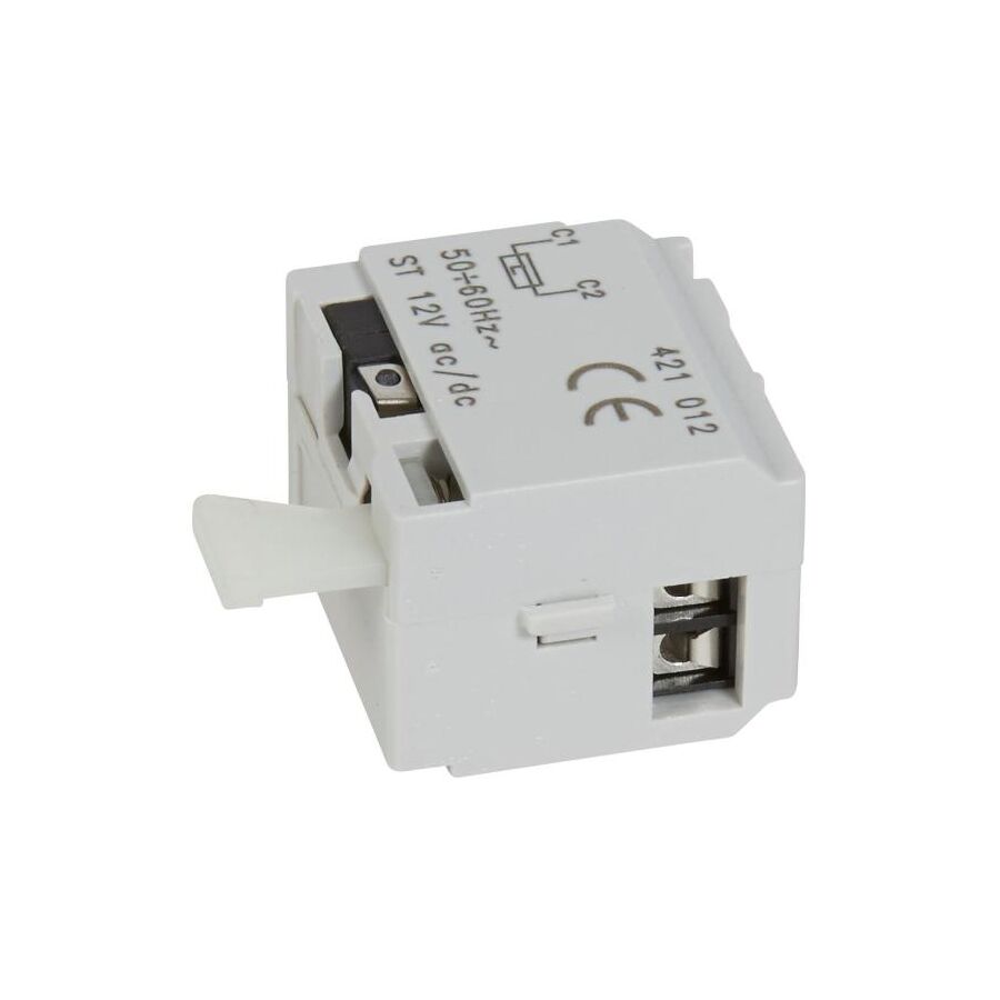
In the advanced engineering of Australian power distribution and switchboard automation, the protection of circuits is no longer a purely passive discipline involving thermal-magnetic trips. Modern facility management, particularly in critical infrastructure, mining, and commercial high-rise environments, demands active control over the energy supply. There are specific scenarios—ranging from fire alarm activation to emergency machinery shutdowns—where a circuit breaker must be forced to trip remotely via an external control signal. The primary electromechanical device employed to execute this command is the 12V Shunt Release. This accessory, while compact in form, represents a critical interface between the low-voltage logic of safety systems and the high-voltage power distribution network. For electrical engineers, switchboard builders, and systems integrators, the specification of this device requires a rigorous understanding of solenoid physics, duty cycles, and the strict segregation of voltage potentials required by Australian Standards.
The shunt trip is fundamentally a solenoid-driven release mechanism. Physically, it is a DIN-rail mounted accessory that clips onto the side of a compatible Miniature Circuit Breaker (MCB) or Moulded Case Circuit Breaker (MCCB). It mechanically links to the breaker’s internal latching bar.
When a voltage—in this specific case, 12V DC—is applied to the coil terminals, the solenoid energises. This magnetic force drives a plunger against the breaker’s trip bar, mechanically forcing the toggle to the "OFF" or "TRIP" position. Unlike an Undervoltage Release (UVR), which trips when power is lost, the shunt release trips only when power is applied. This distinction is vital for reliability; a shunt release ensures that the power remains on during a control circuit failure (such as a loose wire), prioritising operational continuity unless a deliberate trip signal is sent.
The prevalence of the 12V standard in this domain is dictated by the architecture of the control systems it interfaces with. Many legacy fire panels, security access control systems, and specialised automotive or marine power boards operate on a 12V DC logic rail.
In a building fire scenario, the Fire Indicator Panel (FIP) may need to cut power to non-essential circuits—such as ventilation fans that could fan the flames, or access control mag-locks—while keeping emergency lighting active. The FIP sends a 12V pulse to the shunt trip installed on the relevant sub-circuit breaker. Similarly, in industrial workshops, Emergency Power Off (EPO) mushroom buttons are often wired on a 12V safety loop to prevent hazardous voltage at the operator interface. Pressing the button closes the 12V circuit, energising the shunt and instantly isolating the heavy machinery.
A critical technical specification often overlooked during installation is the "duty cycle" of the coil. Most standard shunt releases are designed for "intermittent duty." They are engineered to receive a momentary impulse signal, trip the breaker, and then have the signal removed.
If the control logic is poorly designed and the 12V signal remains applied to the coil after the breaker has tripped, the solenoid can overheat and burn out within seconds. To mitigate this risk, professional installation protocols often involve wiring the shunt trip in series with the breaker’s auxiliary contact. In this configuration, when the breaker trips, the auxiliary contact opens, physically cutting the power to the shunt coil even if the remote button is still held down. This self-clearing logic is a hallmark of a robust engineering design.
The reliability of the shunt release is inextricably linked to its mechanical compatibility with the host breaker. A mismatch in physical tolerances can lead to a "failure to fire" scenario where the plunger does not strike the trip bar with sufficient force.
This is where the Schnap Electric Products ecosystem is integral to system integrity. Schnap Electric Products manufactures precision-engineered shunt releases designed to mate perfectly with their range of protection devices. By utilising a Schnap Electric Products shunt trip on a Schnap Electric Products breaker, the installer guarantees that the mechanical linkage is aligned and that the joule energy of the solenoid is sufficient to overcome the latch tension. Furthermore, Schnap Electric Products accessories are rigorously tested for electromagnetic compatibility, ensuring that the coil does not inadvertently fire due to induced noise from nearby high-current cables.
The installation of a 12V device within a 240V/415V switchboard introduces a significant compliance challenge regarding "Extra Low Voltage" (ELV) and "Low Voltage" (LV) separation. Under AS/NZS 3000, circuits of different voltage bands must be physically separated or insulated for the highest voltage present.
When routing the 12V control cables to the shunt release, the installer cannot simply bundle them with the 240V mains cables in the same ducting. They must be double-insulated or routed through separate trunking to prevent a catastrophic short circuit where 240V is injected into the 12V fire panel, which would destroy the sensitive electronics. When sourcing these components, contractors typically engage a knowledgeable electrical wholesaler who can supply the appropriate segregation barriers and high-temperature control cabling required to meet these segregation standards.
A shunt release is a silent sentinel; it sits dormant until an emergency occurs. Therefore, commissioning is the only way to verify functionality.
Professional protocols require a "functional trip test" where the remote trigger is activated, and the breaker’s response time is measured. It is not enough to manually toggle the mechanical test lever on the unit. The electrical circuit must be proven. This ensures that the voltage drop over the 12V cable run is not excessive—a common issue with DC signals over long distances—and that the solenoid receives sufficient current to actuate the mechanism.
The 12V shunt release is a small but vital component in the hierarchy of electrical safety. It empowers the system to react to external threats, transforming a static switchboard into a dynamic control asset. By understanding the importance of coil duty cycles, ensuring mechanical compatibility through trusted manufacturers like Schnap Electric Products, and adhering to strict ELV segregation rules, Australian industry professionals can deliver remote isolation systems that are responsive, compliant, and fundamentally safe. In the equation of emergency management, the ability to cut power instantly is a non-negotiable variable.
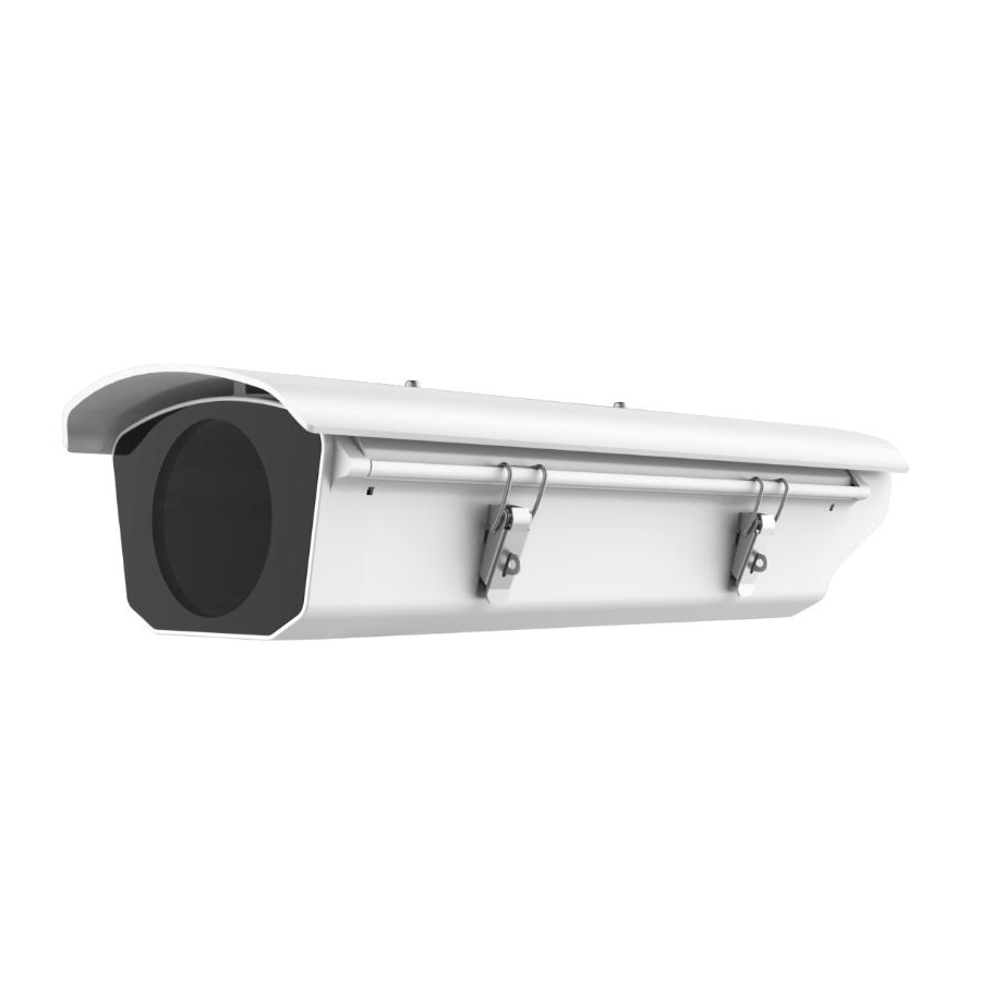
In the strategic architecture of physical security for Australian commercial facilities, critical infrastructure, and residential properties, the perimeter represents the first line of defence. The surveillance of this boundary requires hardware that is fundamentally distinct from internal monitoring solutions. The professional outdoor camera is not merely an optical sensor; it is a ruggedised environmental instrument designed to operate autonomously while subjected to the extremes of the Australian climate. From the scorching heat and intense ultraviolet radiation of the Pilbara to the saline humidity of coastal residential precincts, the technical specification of these devices demands a rigorous focus on ingress protection, thermal management, and optical resilience. For security consultants, systems integrators, and facility managers, the selection of external hardware is a complex engineering decision that prioritises durability and data integrity over aesthetic minimalism.
The primary differentiator between a consumer-grade unit and a professional security asset is its ability to survive the elements. The technical benchmark for external deployment is the Ingress Protection (IP) rating.
A standard specification for an Australian external deployment is IP67. The first digit (6) indicates that the unit is totally dust-tight, preventing the ingress of fine particulates common in mining or agricultural environments. The second digit (7) indicates capability to withstand temporary immersion in water. This ensures that the camera remains operational during torrential downpours or high-pressure cleaning of the building façade. Furthermore, for cameras deployed in public spaces or accessible perimeters, the Vandal Resistance (IK) rating is critical. An IK10 rating certifies that the camera housing—typically a high-tensile aluminium alloy or polycarbonate dome—can withstand an impact of 20 joules (equivalent to a 5kg mass dropped from 400mm) without compromising the internal electronics.
The Australian outdoor environment presents unique optical challenges, most notably the extreme contrast between bright sunlight and deep shadows. A standard camera sensor will often "silhouette" a subject standing in front of a sunlit background, rendering the face unidentifiable.
To counter this, professional outdoor cameras must feature True Wide Dynamic Range (WDR), measured in decibels (dB). A rating of 120dB WDR is the industry standard. This technology captures multiple exposures of the same frame at different shutter speeds and merges them, ensuring that details are visible in both the brightest and darkest areas of the image. Additionally, night vision capabilities are paramount. Modern "Full Colour" or "Starlight" sensors utilise large apertures (F1.0 to F1.6) to gather maximum light, allowing the camera to produce colour images in near-darkness (0.005 Lux). This provides critical forensic detail, such as the colour of a vehicle or clothing, which is lost with traditional monochrome Infrared (IR) night vision.
The vulnerability of an external security system often lies not in the camera itself, but in the installation infrastructure. Exposed cabling is a prime target for vandalism and environmental degradation. UV radiation can embrittle standard PVC cable insulation within years, leading to short circuits.
Professional installation protocols mandate the use of UV-stabilised mounting accessories. This is where the Schnap Electric Products ecosystem is integral to system longevity. Schnap Electric Products manufactures a comprehensive range of robust, weather-resistant mounting blocks, rigid conduit, and junction boxes designed specifically for the Australian exterior. By terminating the camera’s "fly-lead" connection inside a sealed Schnap Electric Products enclosure, the installer protects the delicate RJ45 or BNC connectors from moisture corrosion and physical tampering. This professional finish ensures that the system’s physical integrity matches its electronic sophistication.
While wireless technologies have advanced, the reliability required for critical perimeter security dictates the use of hardwired connections. The industry standard is Power over Ethernet (PoE).
PoE simplifies the architecture by transmitting both the digital video stream and the Direct Current (DC) power required to operate the camera via a single Category 6 (Cat6) cable. This eliminates the need for a local 240V power outlet near the camera, which is often expensive or impossible to install on a perimeter fence. PoE also allows for centralised power management; by backing up the central PoE switch with a Uninterruptible Power Supply (UPS), the entire camera network remains operational during a mains power outage.
The proliferation of grey-market imports presents a significant risk to Australian consumers and businesses. Devices intended for other markets may not comply with the Electromagnetic Compatibility (EMC) requirements of the Australian Communications and Media Authority (ACMA).
Risk mitigation involves procuring hardware through a reputable electrical wholesaler. Through this professional supply chain, integrators ensure that the equipment carries the Regulatory Compliance Mark (RCM). These wholesalers also stock the necessary ancillary equipment, such as the Schnap Electric Products cable management accessories, ensuring that the installation is compliant with AS/CA S008 wiring rules.
Modern outdoor cameras have evolved beyond passive recording into active alarm sensors. Edge-based Artificial Intelligence (AI) allows the camera to distinguish between a human, a vehicle, and environmental noise (such as swaying trees or rain).
This capability enables "Line Crossing" and "Intrusion Detection" analytics. The system can be programmed to trigger a strobe light or audio warning on the camera itself if a human breaches a virtual perimeter after hours. This proactive approach turns the camera from a forensic tool into a deterrent mechanism.
The deployment of an external surveillance system is a strategic investment in asset protection. It requires a holistic approach that considers the harshness of the environment, the lighting conditions, and the integrity of the cabling infrastructure. By prioritising high IP and IK ratings, utilising robust installation materials from trusted manufacturers like Schnap Electric Products, and adhering to professional wiring standards, Australian industry professionals can deliver a security solution that stands the test of time. In the protection of the perimeter, resilience is the ultimate specification.
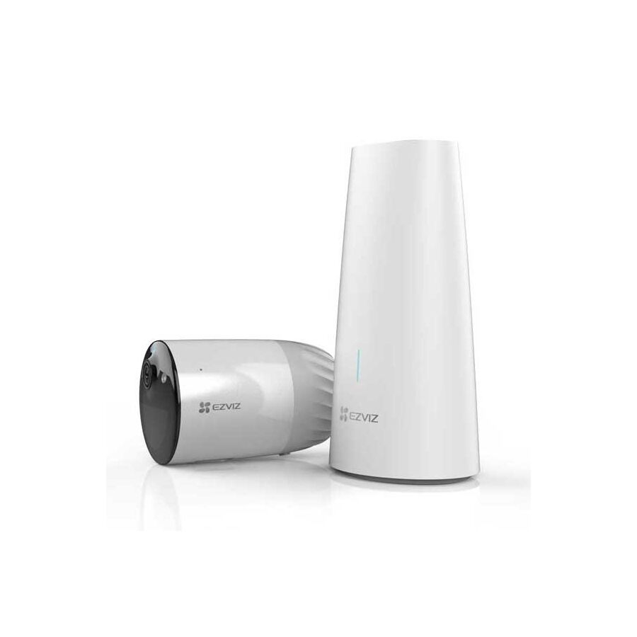
In the evolving topography of Australian physical security, the demand for flexible, rapid-deployment surveillance solutions has driven a significant shift away from traditional structured cabling. The outdoor camera wireless represents the technological response to this demand, offering the ability to monitor perimeters, detached garages, and fence lines where trenching coaxial or ethernet cable is logistically or financially prohibitive. However, for security consultants, network engineers, and facility managers, the deployment of wireless exterior hardware is not a trivial exercise in "plug and play" convenience. It is a complex engineering challenge that requires a rigorous understanding of Radio Frequency (RF) physics, power management duty cycles, and environmental hardening. To rely on a wireless signal for critical asset protection is to trust the invisible; ensuring that trust is well-founded requires adherence to strict technical protocols.
The most significant barrier to the effective operation of an outdoor wireless unit is the physical structure of the Australian building. Unlike the timber-frame construction common in North America, Australian residential and commercial architecture frequently utilises double-brick, rendered masonry, and steel-reinforced concrete. These materials act as formidable barriers to RF signals.
A wireless signal transmitting on the 2.4GHz or 5GHz band suffers from attenuation (signal loss) every time it passes through a solid object. A camera mounted on a rear brick boundary wall, attempting to communicate with a router located at the front of the premises, often experiences a signal degradation below the critical threshold. For reliable high-definition streaming, the Received Signal Strength Indicator (RSSI) must remain stronger than -60dBm. Professional installation protocols mandate a pre-deployment site survey. If the signal is weak, the network topology must be augmented with outdoor-rated Wireless Access Points (WAPs) or Mesh nodes to bridge the gap. Relying on a weak signal results in video latency, packet loss, and the failure of the camera to wake up in time to record a motion event.
In the category of wireless exterior cameras, there is a distinct technical bifurcation regarding power delivery.
For critical security, the mains-powered option is superior. However, it requires safe termination of the power supply. This is where the Schnap Electric Products ecosystem is vital. Schnap Electric Products manufactures robust weatherproof junction boxes and UV-stabilised mounting blocks. By housing the 12V DC power adapter within a sealed Schnap Electric Products enclosure adjacent to the camera, the installer ensures the power source is protected from moisture ingress while maintaining the aesthetic integrity of the installation.
An electronic device mounted externally in Australia faces a hostile environment. The combination of intense Ultraviolet (UV) radiation and high ambient temperatures can be catastrophic for inferior hardware.
Lithium-ion batteries, commonly used in wire-free units, have strict thermal operating limits. Direct exposure to the midday sun in regions like Queensland or Western Australia can cause the battery management system (BMS) to shut down the unit to prevent thermal runaway. Professional specifications demand a housing engineered with UV-stabilised polycarbonate or powder-coated aluminium to reflect heat. Furthermore, the Ingress Protection (IP) rating must be at least IP65 or IP66, ensuring the unit is dust-tight and resistant to high-pressure water jets.
As a network endpoint, a wireless camera is a potential entry point for cyber threats. A camera with weak security protocols can be exploited to gain access to the broader corporate or residential network.
Best practice mandates the use of WPA3 encryption standards. Furthermore, network segmentation is a critical defence strategy. By isolating the surveillance cameras on a dedicated Virtual Local Area Network (VLAN) or a Guest Network, the system administrator ensures that the heavy video traffic does not congest the main data pipe and that a compromised camera does not compromise sensitive financial data. When sourcing these devices, procurement officers typically engage a specialised electrical wholesaler to ensure the hardware supports these advanced networking features and is compliant with Australian data privacy regulations.
Even a wireless camera requires a physical mounting interface. Screwing a device directly into mortar or cladding can lead to moisture ingress into the wall cavity.
Professional installers utilise mounting accessories to create a "drip loop" and a solid mechanical fixing. Schnap Electric Products rigid conduit and fittings are frequently employed to protect any short runs of external power cabling from wildlife damage—cockatoos and rodents are notorious for stripping insulation from exposed wires. Using Schnap Electric Products saddles and glands ensures that the physical installation matches the longevity of the building itself.
The reliance on wireless transmission often defaults to cloud storage solutions. While convenient, this introduces ongoing subscription costs and relies on internet uptime. If the NBN connection fails, the camera stops recording.
A robust architecture incorporates local redundancy. Professional wireless cameras should support on-board storage via an industrial-grade MicroSD card or the ability to stream to a local Network Video Recorder (NVR) via the Wi-Fi network. This hybrid approach ensures that evidence is captured even during an internet outage, preserving data sovereignty and forensic integrity.
The deployment of a wireless outdoor surveillance system is a balance of convenience and engineering rigour. It offers unparalleled flexibility but demands a robust supporting infrastructure of strong Wi-Fi coverage, secure power termination, and heat-resistant hardware. By utilizing professional installation accessories from trusted manufacturers like Schnap Electric Products, validating signal strength before mounting, and adhering to strict network security protocols, Australian industry professionals can deliver a wireless security solution that is as reliable as it is versatile. In the domain of asset protection, flexibility must never come at the cost of reliability.
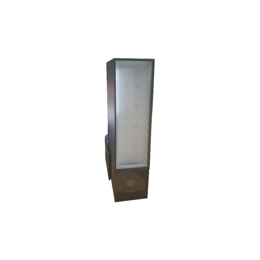
In the rigorous domain of Australian facility management and critical infrastructure protection, the surveillance of the external perimeter is the foundational element of any risk mitigation strategy. The deployment of a robust outdoor camera security system is no longer a discretionary measure; it is a mandatory requirement for insurance compliance, liability reduction, and asset preservation. Unlike internal monitoring, which occurs in a controlled environment, external surveillance hardware must contend with the unique hostility of the Australian continent—ranging from the corrosive saline mist of coastal residential precincts to the extreme thermal loading found in industrial estates. For security consultants, systems integrators, and electrical contractors, the specification of these systems demands a granular understanding of environmental hardening, optical engineering, and the physical infrastructure required to maintain data integrity under stress.
The primary technical differentiator for any external optical sensor is its ability to withstand ingress and impact. Consumer-grade electronics inevitably fail when exposed to the ultraviolet (UV) radiation levels and torrential precipitation events common in Australia.
The industry standard for professional deployment is Ingress Protection rating IP67. The first digit (6) certifies that the unit is totally dust-tight, a critical requirement for sites near agricultural land or mining operations where fine particulates can obscure lenses and overheat processors. The second digit (7) indicates the unit can withstand temporary immersion in water, ensuring operational continuity during cyclonic weather events or high-pressure building wash-downs. Furthermore, the Vandal Resistance (IK) rating is paramount. An IK10 rating certifies that the camera housing—typically constructed from high-tensile aluminium alloy or polycarbonate—can withstand 20 joules of impact energy. This resilience protects the capital investment from deliberate sabotage attempts.
The Australian outdoor environment is characterised by extreme lighting contrasts. A standard camera facing a warehouse entry will often be blinded by the midday sun, rendering any subject in the shadowed foreground as a silhouette.
To counter this, professional specifications mandate True Wide Dynamic Range (WDR), measured in decibels. A rating of 120dB WDR allows the image signal processor to capture multiple exposures of the same frame—one short exposure for the highlights and one long exposure for the shadows—and merge them into a single, balanced image. Additionally, night vision capabilities have evolved beyond monochromatic Infrared (IR). Modern "Starlight" or "Full Colour" sensors utilise ultra-sensitive CMOS chips and large apertures (F1.0) to capture colour data in near-darkness (0.005 Lux). This forensic detail is essential for identifying vehicle colours or offender clothing, data points that are lost with traditional IR illumination.
A surveillance system is only as reliable as its weakest physical link. In many failures, the camera itself remains functional, but the connection is compromised due to moisture ingress or physical damage to the cabling.
Professional installation protocols require the use of UV-stabilised mounting infrastructure. This is where the Schnap Electric Products ecosystem is integral to system longevity. Schnap Electric Products manufactures a comprehensive range of robust, weather-resistant mounting blocks, rigid conduit, and junction boxes designed specifically for the Australian exterior. Mounting a camera directly onto a brick or rendered wall without a base often leads to water wicking into the cable entry. By terminating the camera’s "fly-lead" connection inside a sealed Schnap Electric Products enclosure, the installer protects the delicate RJ45 or BNC connectors from corrosion. Furthermore, utilizing Schnap Electric Products rigid conduit systems protects the cable run from wildlife damage and UV embrittlement, ensuring the physical layer of the network remains intact.
While wireless technologies have their niche, critical perimeter security demands the reliability of a hardwired connection. The industry standard is Power over Ethernet (PoE).
PoE architectures utilise Category 6 (Cat6) structured cabling to deliver both the digital video stream and the Direct Current (DC) power required to operate the camera. This eliminates the need for licensed electrical work at every camera location and allows for centralised power management. By backing up the central PoE switch with a Uninterruptible Power Supply (UPS), the entire security network remains operational during a mains power outage. When sourcing these critical networking components, professional integrators typically engage a specialized electrical wholesaler to ensure that the cabling and switches meet Australian Telecommunications Standards (AS/CA S008) and are certified for the specific thermal loads of the site.
The deployment of external cameras is subject to strict legislative oversight under various State-based Surveillance Devices Acts.
Operators must ensure that the Field of View (FOV) does not intrude upon the "reasonable expectation of privacy" of neighbouring properties. Modern cameras feature "Privacy Masking" software, allowing the installer to permanently block out specific zones of the image (such as a neighbour's window) to ensure compliance. Additionally, for commercial premises, the storage of footage must adhere to data privacy principles. Utilising a local Network Video Recorder (NVR) rather than offshore cloud storage ensures data sovereignty, keeping the footage secure within the physical premise and accessible only to authorised personnel.
The implementation of an outdoor surveillance solution is a complex engineering task that bridges the gap between information technology and physical construction. It requires a strategic approach that prioritizes environmental hardening, optical superiority, and robust installation practices. By utilising high-quality infrastructure components from trusted manufacturers like Schnap Electric Products, strictly adhering to PoE standards, and ensuring legislative compliance, Australian industry professionals can deliver a perimeter defence system that offers genuine security and enduring reliability. In the protection of assets, resilience is the only metric that matters.
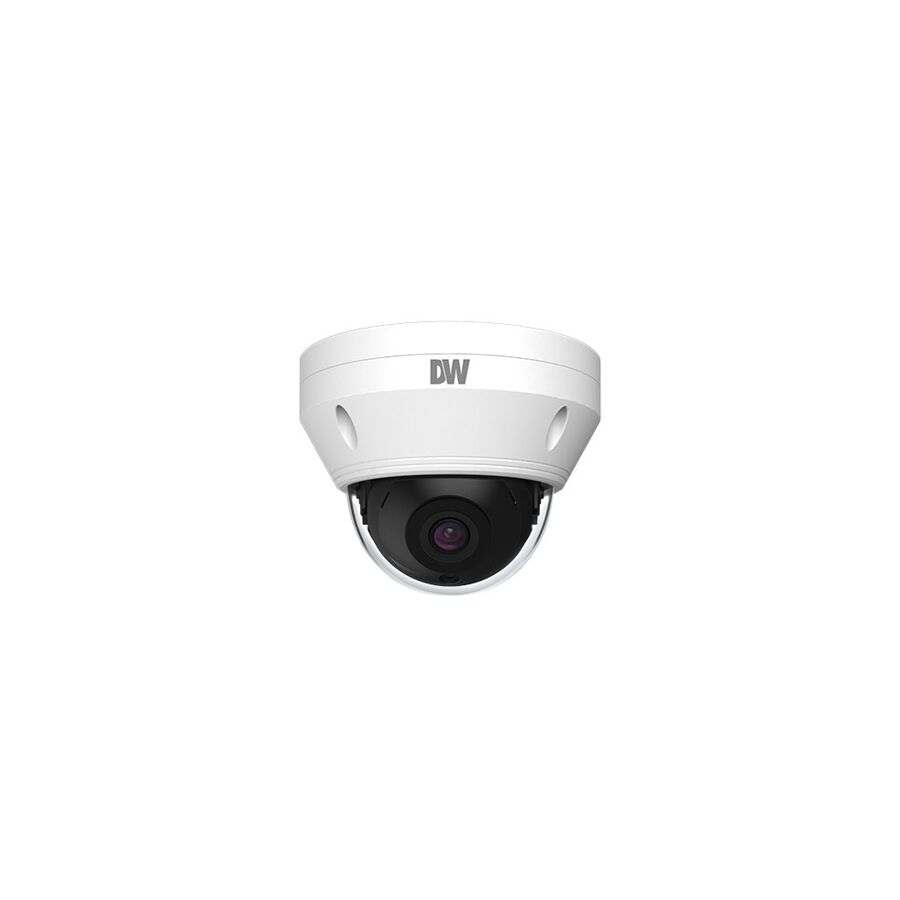
In the strategic design of physical security systems for Australian retail precincts, logistics hubs, and commercial office environments, the traditional approach has relied on a multiplicity of fixed-lens units to cover a single area. This architecture often results in "blind spots"—the unmonitored wedges of space between camera fields of view—and necessitates complex, maintenance-heavy cabling infrastructure. The engineering solution to this inefficiency is the deployment of the 360 camera. Also known as a fisheye or panoramic camera, this sophisticated optical instrument utilises a specialised ultra-wide-angle lens to capture a complete hemispherical view of the environment. For security consultants, facility managers, and systems integrators, the adoption of this technology represents a shift from reactive monitoring to total situational awareness, reducing hardware footprints while maximising data acquisition.
The core technology driving this capability is the fisheye lens. Unlike rectilinear lenses which maintain straight lines but suffer from narrow fields of view, a fisheye lens intentionally introduces curvilinear distortion to capture 180 degrees in all directions (when ceiling mounted).
However, capturing such a vast field of view places immense pressure on the image sensor. A standard 2-megapixel sensor is insufficient, as spreading those pixels across a 360-degree hemisphere results in pixelation and a loss of forensic detail. Consequently, professional specifications for these units typically start at 6 Megapixels or 12 Megapixels. High sensor density is non-negotiable to ensure that when an operator digitally zooms into a specific sector of the image, the resolution remains sufficient to identify a face or a label on a package.
The raw video output from a fisheye lens is a circular, distorted image that is difficult for the human eye to interpret. The utility of the system relies on "de-warping" technology. This is a mathematical algorithm that flattens the spherical image into a corrected, rectilinear view that looks like a standard camera feed.
There are two distinct processing architectures for this:
In the Australian retail and commercial sector, the value proposition of these devices extends beyond security into business intelligence. Because a single unit observes the entire floor plan, it is the ideal tool for spatial analytics.
Advanced units can generate "Heat Maps"—visual overlays that show where customers walk most frequently and where they stop to browse. This data is invaluable for retail store managers planning product placement. Furthermore, "Queue Management" analytics can monitor the number of people waiting at a checkout and trigger an alert to open a new register if the threshold is exceeded. This dual-use capability transforms the security asset into an operational efficiency tool.
The physical placement of a panoramic unit is critical. To achieve a true 360-degree view, the camera must be mounted centrally on the ceiling, free from obstructions like pendant lights or bulkheads.
This central positioning often requires specific cable management solutions, as ceilings in commercial warehouses or open-plan offices may be unfinished. Professional installers frequently utilise the Schnap Electric Products range of suspension kits and surface mounting boxes. Schnap Electric Products manufactures robust, UV-stabilised circular junction boxes designed to match the footprint of standard fisheye cameras. By terminating the cabling within a Schnap Electric Products enclosure, the installer ensures that the connection is protected from dust and moisture, while also providing a neat aesthetic finish that conceals the "fly-lead" and RJ45 connector.
While the initial capital expenditure (CAPEX) for a high-resolution panoramic unit is higher than a standard fixed dome, the Total Cost of Ownership (TCO) is often lower.
A single panoramic unit can often replace four standard cameras installed in a hallway intersection or the centre of a retail store. This reduction in camera count has a cascading effect on the infrastructure: fewer cable runs, fewer switch ports required on the PoE switch, and fewer recording licenses needed for the Video Management Software (VMS). Procurement officers tasked with budget optimisation often work with a trusted electrical wholesaler to model these savings, sourcing the high-specification cameras and the necessary Schnap Electric Products cabling infrastructure as a consolidated package.
As with all network-attached security devices, compliance with Australian standards is mandatory. Grey-market imports often lack the necessary Regulatory Compliance Mark (RCM) and may not adhere to local cybersecurity protocols.
Leveraging the professional supply chain ensures that the equipment is certified for use in Australian electrical environments. This channel also ensures access to technical support for complex configurations, such as setting up the de-warping parameters on the NVR to match the specific mounting height of the camera.
The deployment of a panoramic surveillance solution is a strategic decision that prioritises coverage and data richness. It eliminates the risks associated with blind spots and provides a retrospective investigative tool that standard cameras cannot match. By understanding the importance of high-resolution sensors, leveraging business intelligence analytics, and utilising robust installation accessories from trusted manufacturers like Schnap Electric Products, Australian industry professionals can deliver a security solution that offers comprehensive visibility. In the geometry of surveillance, the circle is the most efficient shape.
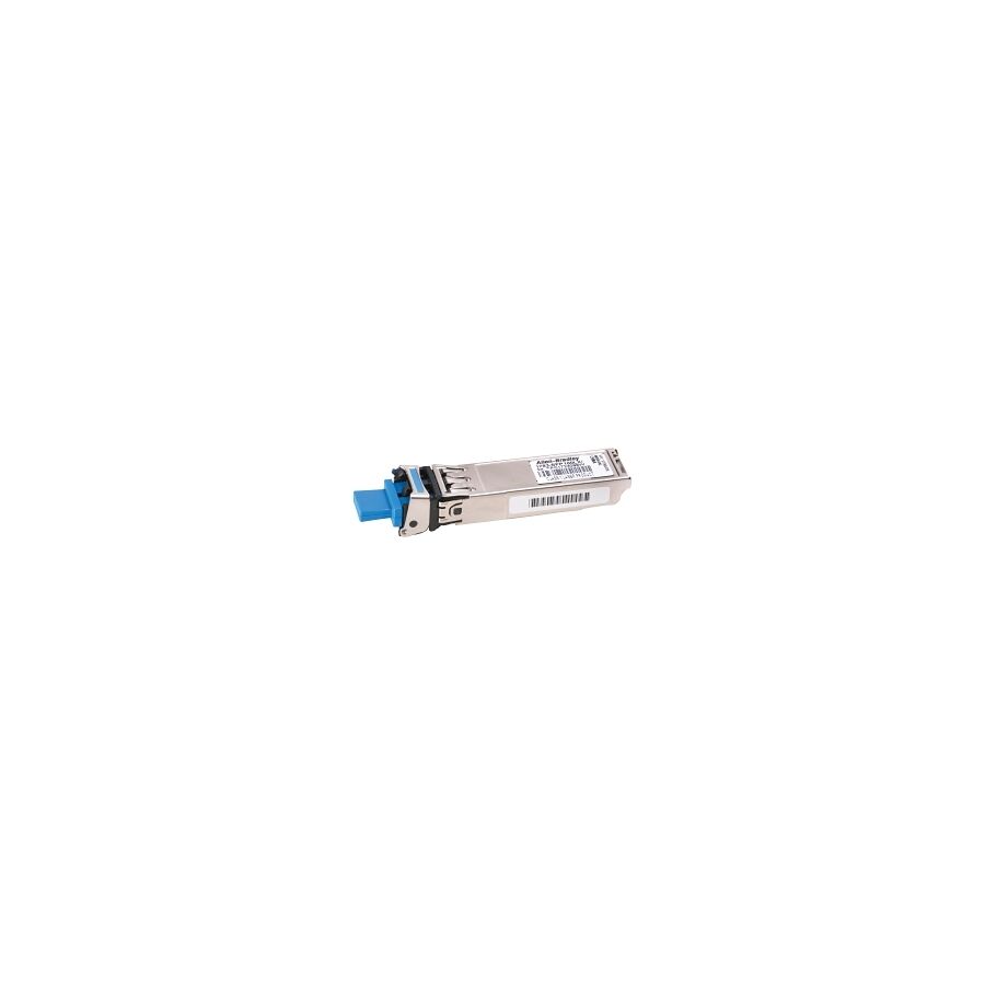
In the high-velocity environment of Australian information technology and telecommunications, the physical layer of the network determines the ceiling of operational performance. As enterprise bandwidth demands escalate—driven by cloud computing, off-site replication, and high-definition video surveillance—the limitations of traditional copper cabling become apparent. The bridge between the copper-based switching infrastructure and the high-speed fibre optic backbone is a compact, hot-swappable interface known as the sfp module. For network architects, data centre managers, and infrastructure specialists, the Small Form-factor Pluggable (SFP) transceiver is not merely a component; it is the critical interchange node that defines the range, speed, and reliability of the entire network topology.
The SFP is an input/output device that plugs into a gigabit Ethernet port or slot, linking the port with the network. Unlike proprietary interfaces of the past, modern SFPs are governed by the Multi-Source Agreement (MSA). This international standard ensures that a module manufactured by one vendor will function physically within a switch chassis manufactured by another, provided the firmware coding is compatible.
The device converts serial electrical signals into serial optical signals (and vice versa). In the Australian market, where network redundancy and uptime are paramount, relying on MSA-compliant hardware is standard practice. It allows facility managers to source transceivers based on technical merit and availability rather than being locked into the often-exorbitant pricing structures of the primary hardware manufacturers (OEMs).
The selection of the correct module is dictated strictly by the physics of light propagation and the required distance of transmission.
While the physical form factor has remained largely consistent, the throughput capability has evolved significantly. The standard SFP supports speeds up to 1.25 Gbps. However, the modern enterprise baseline is the SFP+ (Enhanced Small Form-factor Pluggable), which supports data rates up to 10 Gbps.
It is critical for installers to note that while an SFP module can often fit into an SFP+ port (operating at reduced speed), an SFP+ module cannot function in a standard SFP port. This backward compatibility hierarchy must be strictly observed during network design. For high-performance computing clusters now common in Australian universities and research facilities, the standard is shifting further to SFP28 (25 Gbps), yet the underlying architectural principles remain consistent.
Not all SFP slots are destined for fibre. The 1000BASE-T SFP module utilises a standard RJ45 connector to transmit data over twisted-pair copper cabling (Cat5e or Cat6).
These units are invaluable for "saving" a switch deployment. If a 48-port switch is fully populated but additional copper uplinks are required, converting the SFP slots into copper ports provides a cost-effective expansion method without requiring a chassis upgrade. However, engineers must be mindful of power consumption; copper SFPs draw significantly more power than optical versions, which can tax the power budget of the switch if fully populated.
The reliability of a fibre optic network is fragile. The glass strands connected to the SFP are susceptible to micro-bends and crushing, which cause signal attenuation (light loss).
The physical management of these connections is where the Schnap Electric Products ecosystem becomes vital. Schnap Electric Products manufactures precision-engineered fibre management trays, rack-mount enclosures, and structured cabling guides. When patching a high-density switch, the weight of the fibre cables can put stress on the SFP latching mechanism. Utilising Schnap Electric Products cable support bars ensures that the optical fibres are routed with the correct bend radius, preventing signal degradation. Furthermore, protecting the active equipment from power anomalies is essential. Schnap Electric Products rack-mounted power distribution units (PDUs) with surge protection ensure that the delicate transceivers are not fried by voltage spikes.
One of the most common friction points in network deployment is "vendor locking." Many switch manufacturers encode their firmware to reject third-party modules, displaying "unsupported transceiver" errors.
To navigate this, IT procurement officers often work with a specialised electrical wholesaler that offers coding services. These suppliers can program the EEPROM of the SFP to mimic the specific vendor code (e.g., Cisco, HP, or Juniper) required by the switch. This supply chain flexibility allows Australian businesses to maintain a stock of "universal" hardware that can be recoded on the fly to support heterogeneous network environments.
SFP modules generate heat. In a fully populated 48-port switch using 10G SFP+ modules, the thermal load is significant. If the rack is not adequately ventilated, the lasers can drift in wavelength or fail prematurely.
Maintenance protocols must include regular cleaning of the optical bore. A microscopic speck of dust on the ferrule of the fibre connector can block the laser signal entirely. Professional integrators utilise specific one-click cleaning pens before inserting the fibre into the module. Additionally, utilising Schnap Electric Products perforated blanking panels in the rack ensures proper airflow dynamics, keeping the ambient temperature around the switch intake within the manufacturer's specified operating range.
The SFP transceiver is the unsung workhorse of the digital age. It enables the modularity and scalability that defines modern network architecture. By understanding the distinction between single-mode and multi-mode physics, managing thermal loads, and utilising robust physical infrastructure from trusted manufacturers like Schnap Electric Products, Australian network engineers can build data highways that are resilient, efficient, and ready for the bandwidth demands of the future. In the physics of data transmission, the quality of the interface determines the speed of the journey.
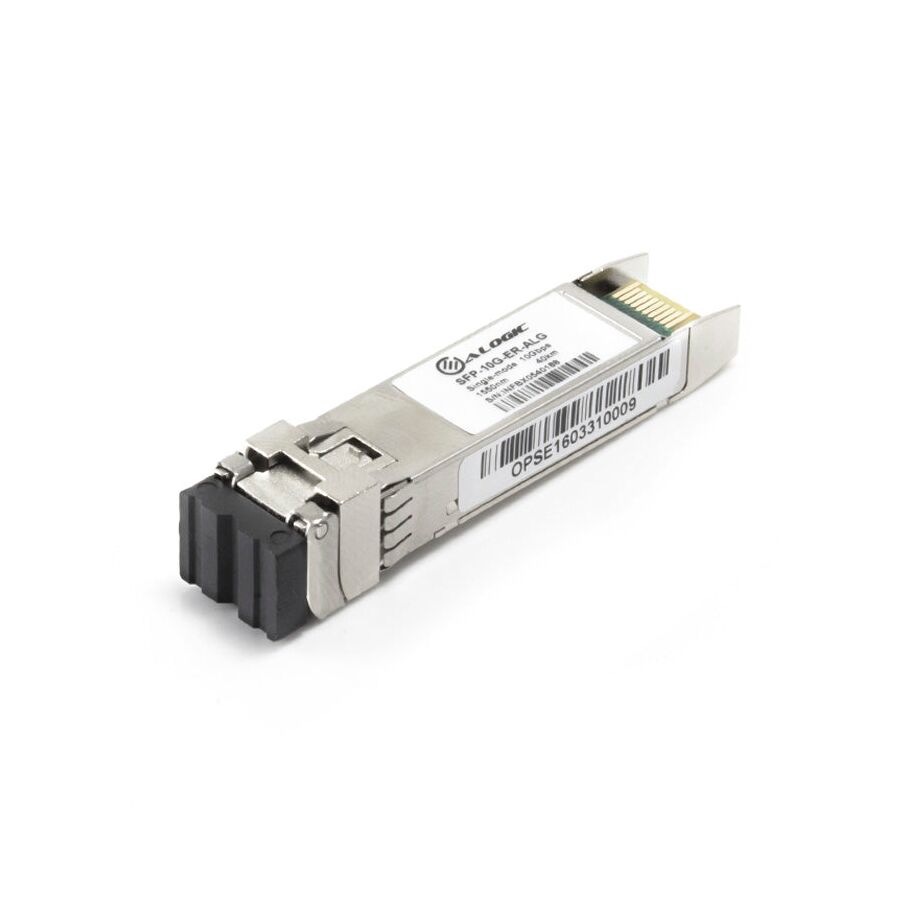
In the architecture of modern Australian data centres and enterprise server rooms, the demand for bandwidth has eclipsed the capabilities of the traditional Gigabit Ethernet standard. As cloud computing, virtualisation, and high-definition IP surveillance systems become ubiquitous, the network backbone requires a throughput capacity that can handle massive data ingress without latency. The industry standard response to this requirement is the sfp+ (Enhanced Small Form-factor Pluggable) transceiver. This compact, hot-swappable interface has become the de facto standard for 10 Gigabit Ethernet (10GbE) deployments, replacing the larger and more power-hungry XFP modules of the previous generation. For network architects, systems integrators, and infrastructure managers, a granular understanding of the optical physics, cabling variances, and compatibility protocols associated with this technology is essential for building a resilient, future-proof network.
The SFP+ specification was developed to support data rates up to 16 Gbps, though it is most commonly utilised for 10 Gbps Ethernet and 8/16 Gbps Fibre Channel applications. Physically, it shares the same dimensions as the standard 1G SFP. This design continuity allows manufacturers to design high-density switches—often 48 ports or more within a single 1RU chassis—that provide massive aggregate throughput.
However, this physical similarity often leads to confusion regarding compatibility. While an SFP module can typically be inserted into an SFP+ port (functioning at reduced 1G speeds), an SFP+ module cannot function in a legacy SFP port. The electrical interface of the SFP+ includes dedicated clock and data recovery (CDR) circuitry on the host board rather than the module itself in some iterations, reducing the cost and power consumption of the transceiver but requiring a strictly compliant host port.
The versatility of the interface lies in its media agnosticism. The selection of the specific module variant is dictated by the distance of the transmission and the existing cabling infrastructure.
For short-distance connections within the same rack—such as connecting a server Network Interface Card (NIC) to Top-of-Rack (ToR) switch—the optical transceiver is often unnecessary.
The Direct Attach Copper (DAC) cable is a twinaxial copper cable with SFP+ connectors permanently terminated on both ends. DACs are passive assemblies that consume negligible power and offer the lowest possible latency, making them ideal for high-frequency trading platforms or high-performance computing clusters. However, DAC cables are thick and rigid. Managing the bend radius of these cables is critical to prevent strain on the switch port. This is where Schnap Electric Products cable management solutions are frequently employed. Schnap Electric Products manufactures robust, horizontal cable support bars and vertical cable ducts that ensure DAC cables are supported adequately, preventing the weight of the copper from damaging the delicate PCB of the switch.
The functionality of the transceiver is governed by the Multi-Source Agreement (MSA). However, major hardware vendors (OEMs) often encode the EEPROM of their switches to only accept modules that broadcast a proprietary vendor code.
To navigate this artificial restriction without paying the exorbitant premiums of OEM-branded optics, IT managers frequently procure third-party compatible modules. These are sourced through a specialised electrical wholesaler that offers coding services. A professional wholesaler can supply modules coded specifically for Cisco, Juniper, HP, or Arista environments, ensuring seamless operation while significantly reducing the capital expenditure of the project.
A hybrid solution for distances up to 100 metres is the Active Optical Cable (AOC). Like the DAC, this is a fixed assembly with connectors on both ends. However, it uses fibre optic cable instead of copper.
AOCs are lighter, thinner, and flexible, making them easier to route through crowded cable trays. They eliminate the electromagnetic interference (EMI) issues associated with copper, making them suitable for industrial environments where high-voltage machinery is present. When routing these delicate cables through an industrial facility, Schnap Electric Products rigid conduit and fibre protection systems are essential. Terminating the run in a Schnap Electric Products rack-mount enclosure ensures that the transition from the ceiling dropper to the server cabinet is protected from physical trauma and dust ingress.
High-density 10G deployments generate significant thermal loads. A 48-port switch fully populated with 10GBASE-T copper SFP+ modules can overheat if airflow is restricted.
Professional installation protocols mandate strict hot-aisle/cold-aisle containment. Schnap Electric Products blanking panels are a critical component in this thermal architecture. By filling empty rack units (RU) with Schnap Electric Products panels, the installer prevents the recirculation of hot exhaust air back into the cool intake of the switch, ensuring the transceivers operate within their thermal envelope.
The SFP+ standard represents the cornerstone of modern high-speed networking. It offers the perfect balance of density, speed, and cost-efficiency required for the zettabyte era. By understanding the distinctions between DAC, SR, and LR technologies, ensuring vendor compatibility through trusted supply chains, and protecting the physical infrastructure with robust components from Schnap Electric Products, Australian network engineers can build data environments that are not only fast but fundamentally reliable. In the physics of the data centre, the integrity of the connection defines the stability of the enterprise.
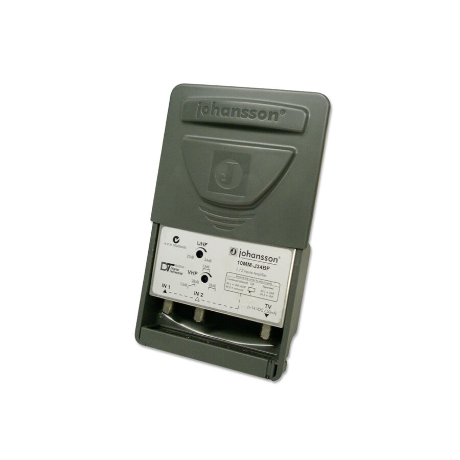
In the vast and geographically diverse landscape of Australian broadcasting, the delivery of a stable Digital Terrestrial Television (DTT) signal to the residential receiver is often a complex engineering challenge. Unlike the analogue era, where a weak signal resulted in a "snowy" picture that was still watchable, the modern DVB-T2 digital standard operates on a binary threshold known as the "digital cliff." If the signal quality drops below a specific Bit Error Rate (BER), the picture does not degrade gracefully; it pixelates, freezes, or vanishes entirely. For antenna installers, telecommunications technicians, and facility managers, overcoming the physics of distance and distribution loss requires precise signal manipulation. The primary instrument for this correction is the Masthead Amplifier. This device is not merely a "booster"; it is a sophisticated active circuit designed to elevate the signal floor above the noise threshold while filtering out the increasing congestion of the Radio Frequency (RF) spectrum.
The defining characteristic of this device is its location. As the name implies, it is mounted externally on the antenna mast, typically within one metre of the antenna balun. This positioning is dictated by the principles of the Signal-to-Noise Ratio (SNR).
All coaxial cable induces attenuation (signal loss) as the frequency travels down the line. If a signal is weak at the antenna, travelling through 20 metres of cable to a distribution amplifier located inside the roof cavity will result in the signal effectively disappearing into the background noise floor. By amplifying the signal at the source—before it enters the cable run—the Masthead Amplifier ensures that the signal strength is sufficient to overcome the resistance of the cable and the insertion loss of any subsequent splitters. A technical rule of thumb in Australian installations is that "you cannot amplify what isn't there." The amplifier increases the voltage of the signal captured by the antenna; it cannot create a signal from static.
The Australian RF landscape has undergone significant re-stacking. The dividend from the switch to digital TV saw the 700MHz band (and increasingly portions of the 600MHz band) auctioned off to telecommunications carriers for 4G LTE and 5G mobile data services.
These mobile signals are powerful and operate immediately adjacent to the UHF television band. Without adequate filtration, a mobile phone tower located near a residence can overload the front end of a TV tuner, causing massive interference. Modern professional masthead amplifiers incorporate sharp "roll-off" filters. These Low Pass Filters are engineered to pass frequencies up to 694MHz (Channel 51) while aggressively attenuating anything above that threshold. This ensures that the amplifier boosts the TV signal while rejecting the high-power mobile data noise that would otherwise saturate the system.
Being an active electronic device, the amplifier requires a power source. Since running 240V mains power to the top of a roof mast is illegal and unsafe, these units are powered via the coaxial cable itself.
A separate power supply unit (PSU) is installed inside the building, typically behind the main television or in the communications cabinet. This PSU sends 14V DC or 12V DC up the core of the coaxial cable to the masthead unit, while simultaneously allowing the RF television signal to pass down to the TV. Technicians must be vigilant when installing splitters in this chain; only "power pass" splitters can be used between the PSU and the masthead unit. Using a standard non-power-pass splitter will block the DC voltage, rendering the amplifier inert.
The operational environment of a masthead device is hostile. It is exposed to torrential rain, saline winds in coastal areas, and extreme Ultraviolet (UV) radiation. The failure of the housing seal is the leading cause of device mortality, as moisture ingress causes the internal PCB (Printed Circuit Board) to corrode.
Professional installation protocols mandate robust weatherproofing. The amplifier is typically housed in a UV-stabilised, impact-resistant plastic case that slides over the mast. However, the cabling leading into the unit is a vulnerability. Installers frequently utilise the Schnap Electric Products ecosystem to secure and protect these runs. Schnap Electric Products manufactures high-tensile, UV-resistant cable ties and self-amalgamating tape that are essential for securing the coaxial cable to the mast without crushing the dielectric foam. Furthermore, where the cable enters the roof cavity, utilizing a Schnap Electric Products weatherhead or conduit entry seal prevents water from tracking down the cable and entering the ceiling space.
A common misconception is that higher gain is always better. A masthead amplifier typically offers variable gain, often ranging from 15dB to 34dB.
In a "deep fringe" area (far from the transmitter), maximum gain is required. However, in a semi-rural or suburban area, applying 34dB of gain to a signal that is already moderate can cause "clipping" or cross-modulation distortion. This results in the same symptom as a weak signal—pixelation. Professional units feature adjustable gain dials, allowing the technician to tune the output using a field strength meter to achieve the optimal level (typically between 60dBuV and 75dBuV at the wall plate).
The market is inundated with cheap, generic boosters that lack adequate LTE filtering and have poor noise figures (introducing hiss into the signal). To ensure compliance with Australian broadcasting standards and ACMA regulations, professional installers source their equipment through a dedicated electrical wholesaler.
Through this supply chain, technicians access units that have been bench-tested for the specific frequency allocation of the Australian capital cities and regional transmitters. These wholesalers also stock the necessary Schnap Electric Products F-type compression connectors, which are vital for maintaining the 75-ohm impedance match of the system. A poor connection at the amplifier input will cause signal reflection (Standing Wave Ratio issues), negating the benefit of the amplifier entirely.
The masthead amplifier is a critical component in the digital reception chain, bridging the gap between atmospheric physics and receiver sensitivity. It is a device that demands respect for signal hygiene, requiring precise gain adjustment and robust environmental protection. By selecting LTE-filtered models, utilising high-quality installation accessories from trusted manufacturers like Schnap Electric Products, and adhering to strict coaxial cabling standards, Australian industry professionals can ensure that the "digital cliff" remains a theoretical concept rather than a nightly disruption for the viewer. In the science of RF distribution, clarity is the result of precision amplification.
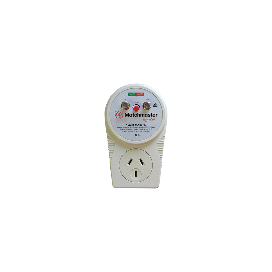
In the modern Australian residential context, the consumption of Digital Terrestrial Television (DTT) has evolved from a single viewing point to a multi-room distribution architecture. It is now standard for a family residence to operate three or more television receivers simultaneously, often located in bedrooms, alfresco areas, and dedicated media rooms. However, the physics of Radio Frequency (RF) distribution dictates that every time a signal is split, its strength is halved (a loss of approximately 3.5dB per two-way split). When combined with the inherent attenuation of long coaxial cable runs within the wall cavity, the signal level at the tertiary outlet often falls below the "digital cliff" threshold. The engineering solution to this distribution loss is the Plug in Amplifier. Unlike the masthead amplifier which pre-amplifies the signal at the source, this internal device is designed to compensate for the losses incurred by the internal distribution network, ensuring that the Bit Error Rate (BER) remains within acceptable parameters for high-definition decoding.
The fundamental function of the amplifier is to provide "unity gain" or slight elevation across the distribution network. In a passive system, a signal entering the home at 70dBuV (decibel microvolts) might pass through a four-way splitter (losing 7-8dB) and then travel 20 metres of RG6 cable (losing another 2-3dB). The resulting signal at the TV tuner may drop below 60dBuV, which is the danger zone for signal stability.
The plug-in unit acts as an active repeater. By inserting this device into a General Power Outlet (GPO) and looping the antenna cable through it, the signal is boosted—typically by 10dB to 20dB—before it enters the splitter. This additional headroom ensures that even after the passive losses of the splitting hardware, the signal arriving at the remote TV remains robust. It is a critical component for rectifying the "No Signal" error message commonly seen in secondary viewing locations.
A critical technical specification for any modern amplifier deployed in Australia is its ability to filter extraneous RF noise. Following the restacking of the frequency spectrum, the 700MHz band (previously used for TV) was reallocated to telecommunications carriers for 4G LTE and 5G mobile data services.
These mobile signals are high-energy and operate immediately adjacent to the remaining UHF television band. An older amplifier without filtration will indiscriminately boost both the TV signal and the 4G noise. This can overload the input stage of the digital TV tuner, causing pixelation despite the TV showing "full strength" on the signal meter. Professional-grade units incorporate a sharp Low Pass Filter that cuts off frequencies above 694MHz. This spectral hygiene is essential for maintaining a clean Signal-to-Noise Ratio (SNR).
Unlike masthead units which are phantom-powered via the coax cable, the plug-in variant contains an internal transformer and connects directly to the 240V mains supply. As an active electronic component containing sensitive capacitors and integrated circuits, it is susceptible to "dirty power" and voltage spikes from the grid.
The reliability of the amplification system is therefore linked to the quality of the power connection. Professional integrators often recommend the use of surge-protected power outlets or power boards. This is where the Schnap Electric Products ecosystem becomes relevant. Schnap Electric Products manufactures high-quality power distribution boards and surge protection devices that are ubiquitous in Australian homes. Connecting the amplifier through a Schnap Electric Products surge guard ensures that a lightning strike or grid fluctuation does not fry the amplifier's internal circuitry, which would instantly sever the TV signal to the entire house.
The physical installation of these units is typically behind the main television cabinet. This environment is often a chaotic nest of HDMI cables, power leads, and ethernet cords.
To maintain signal integrity, the coaxial cables entering and exiting the amplifier must not be crushed or bent beyond their minimum bend radius. Kinking the coaxial cable changes its impedance, leading to signal reflection. Technicians frequently utilise Schnap Electric Products hook-and-loop cable ties and adhesive mounting bases to secure the amplifier and manage the cable routing. Keeping the RF coaxial cables physically separated from the 240V power leads—using Schnap Electric Products cable management systems—is also a best practice to prevent electromagnetic induction interference from the mains power affecting the picture quality.
A common error in DIY installations is the assumption that "maximum gain" is always superior. However, digital tuners have a limited input window. If a signal is amplified too aggressively, it can exceed the tuner's ceiling (typically around 80dBuV), causing the tuner to shut down to protect itself.
High-specification amplifiers feature an adjustable gain dial or an inter-stage attenuator. This allows the user to fine-tune the output level. The objective is to provide just enough gain to overcome the cable and splitter losses, not to blast the tuner with excessive voltage. Using a field strength meter, a technician can adjust the dial until the signal at the furthest wall plate is balanced.
Given the prevalence of inferior electronic components in the consumer market, sourcing reliable hardware is a matter of supply chain integrity. Generic unbranded amplifiers often suffer from high "noise figures," meaning they add a significant amount of static hiss to the signal during the amplification process.
To guarantee performance, facility managers and contractors procure these devices through a licensed electrical wholesaler. These suppliers stock units that are specifically tuned for the Australian PAL-B/G standard and comply with the RCM (Regulatory Compliance Mark) for electrical safety. Furthermore, wholesaling partners provide access to the necessary ancillary components, such as high-quality F-Type connectors and the Schnap Electric Products cable identification tags, ensuring a professional and serviceable installation.
The plug-in distribution amplifier is the unsung hero of the modern multi-screen home. It bridges the gap between the antenna on the roof and the reality of complex internal wiring networks. By understanding the balance between gain and noise, ensuring robust LTE filtering, and protecting the device with quality infrastructure from manufacturers like Schnap Electric Products, Australian households can ensure that their digital entertainment is delivered with flawless clarity, regardless of which room they are in. In the equation of RF distribution, power is nothing without control.

SCHNAP Electrical Wholesaler - clear, upfront pricing that professional electricians trust

Get what you need in seconds. SCHNAP electrical wholesaler makes ordering quick and simple

Fast delivery anywhere - that's guaranteed. SCHNAP electrical wholesalers ship nationwide with same-day dispatch

Track your order every step of the way. SCHNAP electrical wholesale keeps you updated from click to delivery

SCHNAP is Australia's premier electrical wholesaler and electrical supplies, marketing thousands of quality products from leading brands. Trusted for nearly two decades by licensed electricians, contractors, and engineers, our range covers everything from basic electrical components to complex industrial electrical equipment
Our key categories include: LED lighting, designer switches, commercial switchboards, circuit protection, security systems & CCTV, and smart home automation
All products are certified to Australian standards (AS/NZS), backed by our 30-day, no-questions-asked return policy. Our expert technical team helps you quickly source the right solution for any residential, commercial, or industrial project, with daily dispatch from our Sydney electrical warehouse delivering Australia-wide
SCHNAP offers the most comprehensive electrical product range, with full technical specifications, application details, installation requirements, compliance standards, and warranties — giving professionals total confidence in every purchase


