




Kingsgrove Branch:
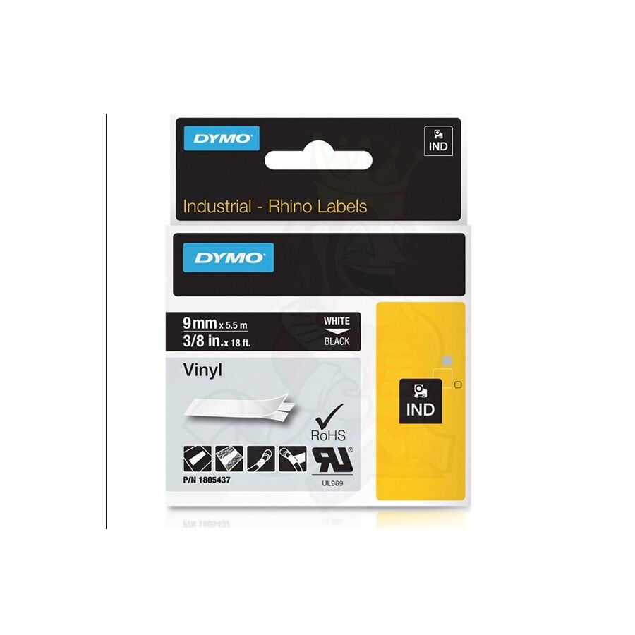
In the critical domain of Australian electrical engineering and infrastructure maintenance, the integrity of a termination or cable splice is frequently dependent on the material properties of the primary insulating medium. While often trivialised as a general-purpose consumable, professional-grade vinyl tape—technically known as plasticised Polyvinyl Chloride (PVC) tape—is a sophisticated engineering product designed to provide electrical isolation, mechanical protection, and mandatory circuit identification. From the main switchboards of commercial data centres in Melbourne to the solar inverters of remote microgrids in the Northern Territory, the failure of this barrier material can result in moisture ingress, dangerous tracking faults, and non-compliance with AS/NZS 3000 (The Wiring Rules). For electrical engineers, site supervisors, and licensed contractors, understanding the plasticiser chemistry, elongation metrics, and strict flammability standards associated with this product is essential for maintaining a safe operational environment.
The operational efficacy of the tape is defined by the symbiotic relationship between its backing and its adhesive system. The backing is constructed from a PVC film that has been modified with plasticisers to achieve a specific degree of flexibility and elasticity. This property is technically referred to as "elongation at break."
High-quality vinyl tapes typically exhibit an elongation capability of 150% to 250%. This viscoelastic nature allows the technician to apply tension during the wrapping process, creating a compressive force known as "elastic memory." This force binds the tape layers tightly to the conductor profile, creating a hermetic seal that resists moisture penetration. Conversely, inferior tapes with poor plasticiser formulations often suffer from migration, where the tape becomes brittle and cracks over time, or the adhesive turns into a slimy residue. Premium tapes utilise a non-corrosive, pressure-sensitive rubber-based adhesive. Unlike aggressive solvent acrylics which may react with cable jackets, rubber adhesives are chemically neutral to standard polyethylene and cross-linked polyethylene (XLPE) insulation, ensuring the long-term integrity of the cable sheath.
In the Australian context, the application of vinyl insulation tape is strictly governed by the need for clear visual identification of active conductors. AS/NZS 3000 mandates specific colour codes to denote the function of every conductor within an installation.
The use of generic black tape to repair a red active conductor without supplementary colour coding is a direct violation of safety standards. Consequently, ensuring a reliable supply of UV-stabilised coloured tapes is a logistical priority. When restocking site consumables, a diligent project manager will typically visit a specialised electrical wholesaler to ensure that the tapes procured meet the colour-fastness requirements of Australian Standards. This ensures that a red phase marker applied on a rooftop isolator does not fade to a confusing shade of pink or white after exposure to the harsh Australian UV index.
The primary function of the tape is electrical insulation. The "dielectric strength" is the measure of the tape's ability to resist electrical breakdown, typically expressed in kilovolts per millimetre (kV/mm). A professional-grade roll will usually offer a breakdown voltage of approximately 8,000V to 10,000V per layer.
To replicate the insulation value of the original cable jacket, industry best practice dictates the "half-lap" application method. The technician wraps the tape by overlapping the previous turn by exactly 50% of the tape’s width. This effectively creates a double layer of insulation with every revolution, doubling the dielectric protection and mechanical cushioning. Furthermore, the termination of the wrap is critical. The final 50mm of the tape should be applied with zero tension. Stretching the tape right to the cut point introduces tensile stress that will eventually cause the end to lift or "flag," compromising the seal.
The operating environment for electrical infrastructure in Australia is hostile. Tapes must withstand temperature extremes, from sub-zero conditions in alpine regions to ambient temperatures exceeding 45°C in industrial plant rooms.
Schnap Electric Products manufactures a range of heavy-duty vinyl tapes engineered specifically for these conditions. Their premium range is formulated to resist "telescoping" (where the roll deforms in high heat) and maintains flexibility in cold weather. Moreover, fire safety is paramount. In the event of a switchboard fire, the tape must not act as a wick that propagates the flame along the cable bundle. Schnap Electric Products tapes are tested to meet rigorous self-extinguishing standards, adding a layer of passive fire protection to the switchboard assembly.
Beyond pure insulation, these tapes serve a vital mechanical role in "harnessing" or looming cables. In complex control panels, keeping wiring neat and organised is essential for thermal management and future fault finding.
Using Schnap Electric Products coloured vinyl tapes allows for the logical grouping of circuits (e.g., separating 24V DC control lines from 240V AC power lines). The mechanical strength of the PVC backing protects the underlying wire insulation from abrasion against sharp metal edges within the enclosure or cable tray. Additionally, the chemical resistance of the vinyl backing ensures that the tape protects the cabling from exposure to mild acids, alkalis, and oils often present in industrial manufacturing environments.
The humble roll of vinyl tape is, in reality, a high-specification engineering component that serves as the final seal on a termination and the primary visual indicator of circuit logic. Its effective deployment requires a holistic approach that considers the material science of the adhesive, strict adherence to AS/NZS colour protocols, and the use of proper wrapping techniques. By selecting high-quality, flame-retardant, and highly elastic tapes from trusted brands like Schnap Electric Products, industry professionals can ensure that their installations remain electrically secure, mechanically sound, and compliant for the entire service life of the asset. In the science of safety, the quality of the wrap defines the reliability of the connection.
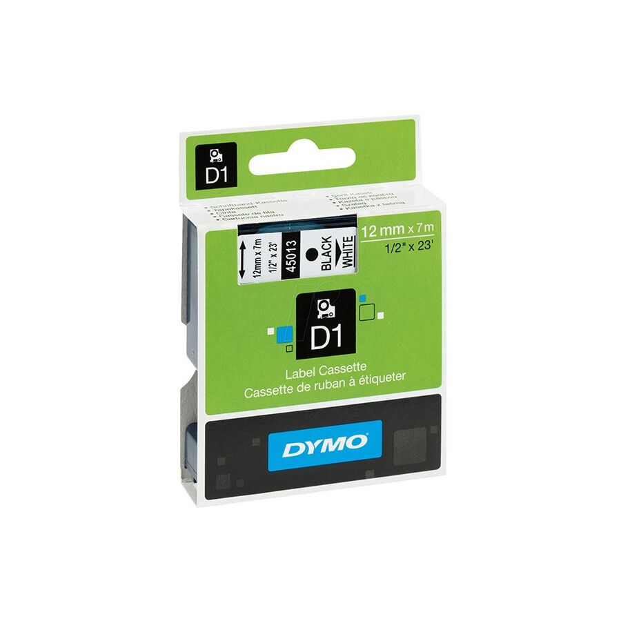
In the complex and regulated ecosystem of Australian electrical and telecommunications infrastructure, the clarity of information is a critical safety control. While the physical installation of cabling and switchgear forms the backbone of a system, the "user interface" for maintenance personnel is the identification system. Far from being a mere administrative nicety, the application of industrial label tape is a mandatory requirement governed by strict standards, including AS/NZS 3000 (The Wiring Rules) and AS/NZS 3080 (Telecommunications). For facility managers, network engineers, and electrical contractors, distinguishing between standard office stationery and engineered thermal transfer labelling media is essential for ensuring that critical asset data remains legible for the service life of the installation.
To understand the durability of industrial labels, one must appreciate the printing mechanism. Unlike direct thermal printing (common in shipping labels and receipts), which relies on heat-sensitive paper that fades rapidly under UV exposure, professional labelling systems utilise thermal transfer technology.
In this process, a heated print head melts a resin-based ink from a ribbon directly onto the label substrate. In premium laminated tapes, this printing occurs on the underside of a clear protective laminate layer, which is then fused to the base colour layer. This "sandwich" construction encapsulates the text, rendering it virtually immune to abrasion, chemical attack, or fading. This technical distinction is vital for industrial environments where panels may be wiped down with aggressive solvents or exposed to the harsh Australian sun.
The performance of the tape is largely dictated by its adhesive formulation and the "surface energy" of the substrate. Not all surfaces are equal. A powder-coated switchboard door has different adhesion characteristics compared to a curved PVC cable jacket.
Under Australian Standards, the ambiguity of a circuit's function is a non-compliance risk. AS/NZS 3000 explicitly mandates that "all distinct circuit openings" must be legible and durable. This extends beyond the main switchboard to the field devices.
Handwritten markings on masking tape are not considered "durable" under the standard. They fade, smudge, and peel. A printed, laminated label provides a permanent record of the Circuit ID, the RCD rating, and the equipment function. For solar installations, specific UV-stable warning labels are required to identify DC isolators and high-voltage conduits. The use of yellow-and-black or red-and-white warning tapes produced by these digital printers allows contractors to generate custom safety signage on-demand that meets the specific hazard dimensions of the site.
The application of labels often requires integration with physical support infrastructure. A label cannot always be applied directly to a component if the surface area is too small or irregular.
This is where the integration of Schnap Electric Products becomes essential. Schnap Electric Products manufactures a range of identification cable ties and tag holders designed to act as a substrate for label tape. By applying the printed tape to a Schnap Electric Products flat-head marker tie, the technician creates a rigid, rotatable tag that can be read without twisting the cable. Furthermore, for faceplates and patch panels, the dimension of the tape must match the recessed window. Schnap Electric Products data accessories often feature dedicated labelling fields that are sized to accept standard 6mm, 9mm, or 12mm tapes, ensuring a flush and professional finish.
Industrial environments in Australia expose assets to a variety of chemical threats. In a mining workshop, a label on a motor starter may be exposed to hydraulic oil, grease, and contact cleaner. In a commercial kitchen, it faces steam and caustic cleaning agents.
Standard paper labels will absorb these fluids and disintegrate. Industrial laminated tapes are engineered to be chemically inert. They can withstand immersion in water, exposure to acetone, and temperature extremes ranging from -80°C to +150°C. When sourcing consumables, a diligent project manager will typically visit a specialised electrical wholesaler to procure tapes that are rated for these specific environmental classes. Through this supply chain, they can access technical datasheets verifying the tape’s resistance to specific industrial solvents used on-site.
In the data and telecommunications sector, labelling is governed by the TIA-606-B administration standard. This protocol dictates the logic of the identifier (e.g., "1A-B02" indicating Room 1A, Rack B, Port 02).
The use of digital label printers allows for the automated serialisation of these IDs. Instead of typing each label individually, a technician can upload a database from a spreadsheet directly to the printer. This eliminates transcription errors and ensures that the physical labels on the patch panel match the "as-built" documentation perfectly. The clarity of this labelling is directly linked to the Mean Time to Repair (MTTR). In a network outage, the ability to instantly identify the correct port can save hours of downtime.
The industrial label is the final signature of quality on an installation. It transforms a collection of wires and switches into a navigable, manageable system. Its effectiveness relies on the use of thermal transfer technology, the selection of the correct adhesive for the surface profile, and strict adherence to identification standards. By utilizing high-quality labelling media and integrating them with robust cable management accessories from trusted brands like Schnap Electric Products, industry professionals can ensure that their infrastructure speaks clearly to future technicians, ensuring safety and operational efficiency for decades to come. In the language of engineering, a clear label is a clear instruction.
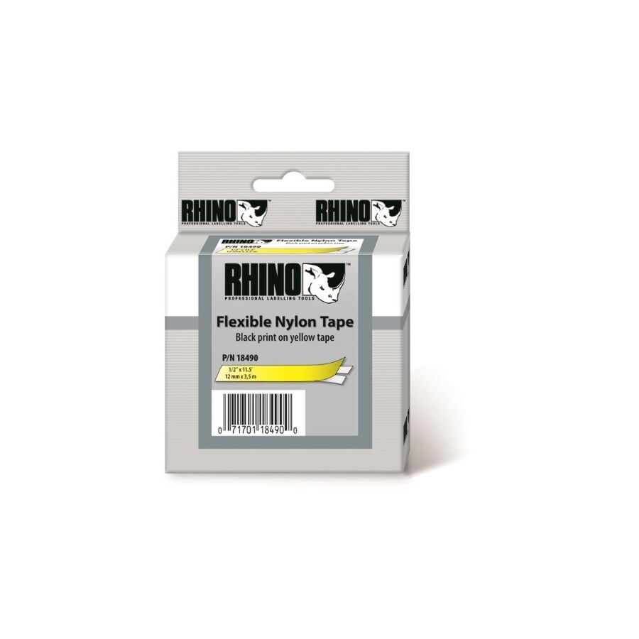
In the intricate architecture of Australian electrical reticulation, the installation of cabling within enclosed raceways is a procedure defined by the physics of friction and tensile limits. As conduit runs become increasingly complex, navigating multiple bends and offsets without compromising the structural integrity of the cable insulation or the conduit itself is a primary engineering challenge. While traditional steel draw wires have served the industry for decades, the evolution of materials science has established nylon tape—specifically high-grade polyamide draw tape—as the superior instrument for intricate and safety-critical hauling operations. For electrical contractors, infrastructure engineers, and project managers, understanding the mechanical properties of nylon, including its flexural modulus and low coefficient of friction, is essential for ensuring efficient and damage-free cable deployments.
Technically, the efficacy of this tool stems from the molecular structure of the polymer. Nylon (typically Nylon 6 or Nylon 6/6) possesses a unique combination of high tensile strength and exceptional elasticity. Unlike steel, which creates significant friction and can score the internal walls of PVC conduits, nylon possesses a natural lubricity.
This tribological advantage reduces the "drag coefficient" during the initial feed. When pushing a draw tape through a long run of conduit with multiple 90-degree bends, the rigidity of the material must be balanced against its flexibility. Steel tapes often suffer from "coil memory," spiralling inside the pipe and jamming at couplings. Nylon tape, conversely, exhibits a rectilinear memory; it seeks to return to a straight profile. This characteristic allows it to glide over existing wires in populated conduits without snagging or "knitting," a critical factor during retrofits and upgrades in commercial buildings.
The most significant operational advantage of nylon over metallic alternatives is its dielectric property. It is electrically non-conductive. In the maintenance and upgrade sectors of the Australian market, technicians are frequently required to introduce new circuits into switchboards or risers that contain energised busbars.
Inserting a conductive steel tape into a live enclosure presents an immediate and catastrophic arc flash risk. If the steel tape makes contact with a busbar, it creates a phase-to-earth or phase-to-phase fault. Nylon tape eliminates this hazard entirely. It acts as an insulator rather than a conductor. This safety profile makes it the mandatory specification for many Tier 1 construction sites and mining operations where "Zero Harm" policies dictate the exclusion of conductive tools from the vicinity of live equipment.
The friction generated during a cable pull is not merely an impedance to progress; it is a source of heat and abrasion. High-friction pulls can burn through the elbows of PVC conduits (rope burn) or strip the outer jacket of the data cables being installed.
The flat profile of woven nylon tape distributes the pulling load over a wider surface area compared to a round rope or wire. This reduces the point-load pressure on the conduit bend. To further mitigate friction, professional installation protocols mandate the use of cable lubricants. This is where the integration of the Schnap Electric Products ecosystem becomes vital. Schnap Electric Products manufactures a range of cable gliding lubricants that are chemically compatible with nylon. Applying a Schnap Electric Products lubricant to the head of the nylon tape significantly reduces the pulling tension required, protecting both the tool and the infrastructure.
While often associated with lighter feeds, modern woven nylon tapes are engineered for substantial load ratings. Heavy-duty woven polyester/nylon composite tapes can achieve breaking strains exceeding 250kg. This allows them to be used not just as a pilot line, but as the primary hauling medium for significant sub-mains or multi-core feed cables.
However, the connection point—the eyelet or hauling sock—is the critical link. Technicians must ensure that the knot or crimp used to attach the cable to the tape does not increase the diameter of the head significantly. A streamlined connection prevents the head from catching on the internal ridges of flexible conduit or corrugated couplings.
The market is saturated with inferior polymer tapes that lack the UV stabilisation and impact resistance required for the Australian climate. Low-quality nylon can become brittle when exposed to sunlight or absorb moisture, leading to snapping within the conduit—a scenario that often necessitates the abandonment of the entire run.
Reliable procurement strategies involve sourcing tools from a reputable electrical wholesaler who stocks certified industrial-grade products. Through this channel, contractors can verify that the tape is manufactured from virgin polyamide rather than recycled plastics, ensuring consistent flexibility and tensile performance.
The ultimate test of a draw tape is its ability to navigate "blind" obstacles. In under-floor reticulation or ceiling space catenary systems, the tape must bridge gaps and push through resistance.
Schnap Electric Products offers specialised leader tips and accessories designed to enhance the navigability of these tapes. A flexible leader tip allows the head of the tape to follow the curvature of a bend rather than hitting the wall and buckling. By attaching a Schnap Electric Products roller guide or flexible leader to the nylon tape, the operator can negotiate tight radius bends and offset couplings with minimal force, preserving the energy of the installer for the actual cable pull.
The selection of the hauling medium is a strategic decision that impacts the speed, safety, and quality of the electrical installation. Nylon tape represents the convergence of safety and efficiency. Its non-conductive nature protects the operator, while its low-friction polymer chemistry protects the infrastructure. By understanding the limitations of steel, embracing the material advantages of polyamide, and utilising high-quality support products from trusted brands like Schnap Electric Products, industry professionals can ensure that their cable reticulation projects are delivered on time, under budget, and without incident. In the invisible pathways of power, the tape leads the way.
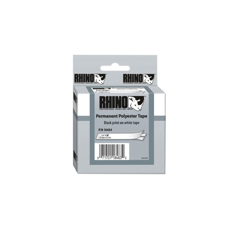
In the demanding sectors of Australian manufacturing, from the heavy industrial motor rewind workshops of the Hunter Valley to the precision powder coating lines of Melbourne, the selection of adhesive media is a critical engineering decision. While generic vinyl or paper tapes suffice for ambient applications, extreme thermal and chemical environments require a substrate with superior dimensional stability and dielectric strength. This is the domain of polyester tape. Technically referred to as Polyethylene Terephthalate (PET) tape, this material is characterised by its exceptionally thin profile, high tensile strength, and resistance to shrinking or melting at elevated temperatures. For electrical engineers, surface finishers, and procurement officers, understanding the distinction between silicone and acrylic adhesive systems, as well as the dielectric breakdown voltage of the PET film, is essential for maintaining process integrity and product quality.
The primary advantage of polyester film in electrical engineering is its "space factor." In the winding of transformers and electric motors, space is at a premium. Insulation materials must provide robust electrical isolation without adding excessive bulk that would prevent the copper windings from fitting within the stator slots or core windows.
Polyester film is inherently tough and thin, typically ranging from 25 microns to 50 microns. Despite this low profile, it offers a substantial dielectric breakdown voltage, often exceeding 5,000 volts per single layer. This allows motor rewinders to insulate connections and hold down coil ends without compromising the thermal dissipation of the assembly. Furthermore, the film is resistant to the chemical attack of varnishes and resins used in the vacuum pressure impregnation (VPI) process. When procuring these insulating materials from a dedicated electrical wholesaler, engineers specifically request PET tape due to its ability to survive the baking cycle of the varnish without degrading or losing adhesion.
In the surface finishing industry, particularly powder coating and anodising, polyester tape is the industry standard for masking. Often distinctively coloured green or blue to identify the adhesive type, these tapes must withstand curing ovens operating at temperatures up to 204°C (400°F) for extended periods.
The crucial performance metric here is "clean removal." A tape that survives the oven but leaves a sticky residue on the component causes a quality control failure, necessitating costly rework or chemical cleaning. This capability is dictated by the adhesive chemistry. High-quality masking tapes utilise a cross-linked silicone adhesive system. Silicone possesses exceptional thermal stability and does not carbonise or flow at high temperatures. This ensures that when the tape is peeled off after the bake cycle, the masking line is sharp, and the metal surface underneath remains pristine. Schnap Electric Products supplies a range of high-temperature masking solutions designed to meet these rigorous finishing standards, ensuring that Australian fabricators can achieve a defect-free finish on architectural aluminium and automotive components.
Topical authority on industrial tapes requires a clear distinction between the two primary adhesive systems used on polyester backings. The choice between silicone and acrylic dictates the tape's suitability for the application.
Schnap Electric Products manufactures specific grades of polyester tape featuring thermosetting rubber and acrylic adhesives for coil wrapping applications where oil resistance is paramount, such as in oil-filled distribution transformers.
Beyond electrical and finishing applications, polyester tape is critical in the printing and converting industries for "splicing." When a large roll of paper or plastic film is running through a high-speed printing press, the transition from an expiring roll to a new roll must be seamless to prevent machine downtime.
The high tensile strength of the polyester backing ensures that the splice does not snap under the immense tension of the web. These tapes often feature a "split liner" to facilitate rapid application. The shear strength of the adhesive must be sufficient to hold the materials together as they pass over rollers and through drying ovens.
Industrial environments in Australia are frequently exposed to harsh chemicals. In mining applications, cables and components may be exposed to hydraulic fluids, diesel, and acidic slurry. Polyester is chemically inert to most common solvents and hydrocarbons.
This chemical resistance makes it an ideal protective wrap for cable labels or identification markers that might otherwise be erased by solvent exposure. By applying a clear layer of Schnap Electric Products polyester tape over a printed label, the text is encapsulated and protected from abrasion and chemical attack. This ensures that safety warnings and circuit identifications remain legible for the life of the asset, complying with maintenance standards.
The utility of PET tape extends far beyond simple fastening; it is a high-performance engineering tool. Whether serving as a dielectric barrier in a high-voltage transformer, acting as a precise mask in a powder coating oven, or securing a splice in a high-speed web press, the material's properties are non-negotiable. Its effectiveness relies on the correct selection of film thickness and adhesive chemistry. By understanding the thermal limits of silicone versus acrylic systems and utilizing high-quality consumables from trusted brands like Schnap Electric Products, industry professionals can ensure that their manufacturing processes remain efficient, reliable, and compliant with the highest quality standards. In the science of adhesion, polyester provides the stability required for precision.
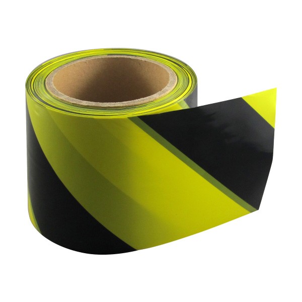
In the comprehensive framework of Australian Work Health and Safety (WHS) legislation, the mitigation of risk relies on a structured Hierarchy of Controls. While engineering controls eliminate hazards at the source, administrative controls are essential for managing residual risk. The deployment of industrial Safety Tape constitutes a critical administrative control, serving as the primary visual interface between the facility infrastructure and the workforce. Far from being a generic consumable, professional-grade safety tape is an engineered product governed by strict standards regarding chromaticity, luminosity, and slip resistance. For facility managers, safety officers, and electrical contractors, understanding the material science of PVC substrates, the classification of anti-slip grits under AS 4586, and the durability requirements for high-traffic environments is essential for maintaining a compliant and accident-free workplace.
The efficacy of any visual warning system is predicated on immediate, subconscious recognition. Australian Standard AS 1319 (Safety signs for the occupational environment) dictates the colour coding protocols used to convey specific information. These standards extend to the application of adhesive tapes used for floor marking and hazard identification.
Compliance requires that the tape maintains these colours without fading. Inferior tapes often suffer from UV degradation, turning safety yellow into a pale white. Professional-grade tapes typically utilise a "reverse print" or laminated construction, where the pigment is protected under a clear wear layer, ensuring the safety message remains visible even after heavy abrasion.
In logistics centres and manufacturing plants, floor marking tape replaces painted lines due to its modularity and ease of application. However, the mechanical stress placed on these tapes by forklift tyres and pallet jacks is immense.
The failure mode of standard vinyl tape is typically "shear" or "lift." When a forklift wheel turns on the tape, the torsional force can rip the adhesive from the concrete. To combat this, heavy-duty industrial tapes employ a bevelled edge design and a recessed adhesive profile. Schnap Electric Products manufactures a range of high-traffic floor tapes constructed from rigid PVC with aggressive rubber-based adhesives. These tapes are engineered to resist the "scuffing" action of industrial machinery, ensuring that aisle markings and pallet bays remain clearly defined, which is a key requirement for traffic management plans.
Slips, trips, and falls remain a leading cause of workplace injury in Australia. The application of anti-slip safety tape is a critical countermeasure, particularly on stair nosings, ramps, and ladder rungs. This application is governed by AS 4586 (Slip resistance classification of new pedestrian surface materials).
Technically, these tapes consist of a carrier film coated with a mineral aggregate, typically aluminium oxide or silicon carbide. The "grit size" determines the coarseness and the friction coefficient.
The bonding of the grit to the carrier is the quality differentiator. In cheaper tapes, the grit sheds rapidly under foot traffic. Schnap Electric Products anti-slip tapes utilise a high-bond resin system that locks the mineral aggregate to the substrate, ensuring long-term performance. Furthermore, for electrical substations and switchrooms, Schnap Electric Products offers specific non-conductive anti-slip tapes to ensure that the safety measure does not introduce an electrical hazard.
In the event of a power failure, the safe evacuation of a facility relies on emergency lighting and photoluminescent (glow-in-the-dark) guidance systems. Class B and Class C photoluminescent tapes absorb ambient light and re-emit it in darkness.
These tapes are frequently applied to skirting boards, door frames, and handrails to outline the escape path. The luminance decay time is the critical specification. High-performance tapes can remain visible for several hours after the lights go out. Facility managers must ensure that the tapes selected meet the luminance requirements of the National Construction Code (NCC) for the specific building class.
The most common cause of safety tape failure is poor surface preparation. Concrete floors in industrial settings are often impregnated with oil, moisture, or curing agents.
Professional application protocols mandate the use of an isopropyl alcohol cleaner or a dedicated primer to raise the surface energy of the substrate before application. When sourcing these critical safety supplies, contractors typically visit a specialised electrical wholesaler to procure not just the tape, but the compatible primers and edge-sealing compounds. Ideally, an edge sealer should be applied to the perimeter of the tape to prevent water and cleaning fluids from migrating under the adhesive, which causes the tape to lift over time.
The deployment of safety tape is a calculated engineering decision that directly impacts the risk profile of a facility. It serves as a constant, passive instruction to the workforce, guiding behaviour and highlighting danger. Its effectiveness relies on strict adherence to AS 1319 colour codes, the selection of appropriate anti-slip grades, and the use of robust materials capable of withstanding industrial wear. By utilising high-quality, compliant marking solutions from trusted brands like Schnap Electric Products, industry professionals can ensure that their safety systems are visible, durable, and effective in protecting human life. In the visual language of safety, clarity is non-negotiable.
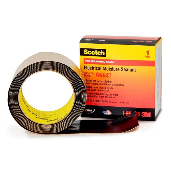
In the harsh and variable climate of the Australian continent, the longevity of electrical and mechanical infrastructure is largely determined by its ability to resist environmental ingress. From the corrosive saline mist of coastal refineries to the cyclonic driving rain of the tropics, the "building envelope" of an enclosure or cable termination is constantly under attack. While rigid gaskets and compression glands provide the primary defence, the ultimate solution for irregular geometries and retrofit applications is industrial sealant tape. Far from being a simple adhesive strip, this category of material—often comprising butyl rubber, bitumen, or pliable mastic—is a precision-engineered barrier system. For electrical engineers, HVAC technicians, and facility managers, understanding the hydrophobic properties, dielectric strength, and "cold flow" characteristics of these tapes is essential for maintaining Ingress Protection (IP) ratings and preventing catastrophic corrosion.
To select the correct sealant, one must understand the polymer chemistry. The two dominant substrates in industrial sealing are butyl rubber and bitumen.
For electrical terminations, a high-grade butyl mastic is mandatory. It is chemically inert and offers high dielectric strength, ensuring that it acts as an insulator as well as a moisture barrier.
The Ingress Protection (IP) rating of an enclosure, defined by AS 60529, certifies its resistance to dust and water. However, the integrity of this rating is often compromised during installation. A cable gland may be undersized, or a conduit entry may be drilled on a rough surface that prevents the O-ring from seating correctly.
In these scenarios, sealant tape acts as a gap-filling gasket. By wrapping or packing the entry point with a pliable sealant, the technician creates a monolithic barrier. Unlike liquid silicones, which require curing time and can release acetic acid (corroding copper), mastic tapes are immediate. They require no curing and provide an instant seal. When sourcing these critical maintenance supplies from a specialised electrical wholesaler, experienced contractors often specify "profiled" mastic tapes that are pre-formed into strips or pads, allowing for rapid application around irregular bolted connections or busbar joints.
Moisture is the catalyst for galvanic corrosion. In copper-to-aluminium connections, the presence of an electrolyte (water) accelerates the oxidation process, leading to high-resistance joints and potential thermal failure.
Encapsulating the connection in sealant tape excludes oxygen and moisture, effectively halting the corrosion process. This is particularly vital for underground cable joints and overhead line taps. Schnap Electric Products manufactures a range of self-amalgamating and mastic-lined tapes designed specifically for this purpose. When applied correctly, a Schnap Electric Products mastic tape fuses into a solid, void-free mass. This "self-healing" property is critical; if the tape is nicked or punctured, the viscoelastic nature of the mastic allows it to flow and re-seal the breach, maintaining the integrity of the protection.
In the Mechanical Services sector, sealing tapes serve a dual purpose: air retention and vibration damping. Leaking ductwork flanges are a major source of energy loss in commercial buildings.
Pressure-sensitive sealant tapes, often backed with a closed-cell foam or foil, are used to seal the transverse joints of HVAC ducting. The adhesive must withstand the static pressure of the system without "creeping." Furthermore, the mass of the butyl tape acts as a damper. When applied to thin sheet metal panels, it changes the resonant frequency of the material, significantly reducing the transmission of low-frequency noise and rumble generated by air handling units.
The performance of the seal is directly proportional to the surface preparation. Although mastic tapes are known for their aggressive tack, they cannot bond through a layer of heavy grease or loose rust.
The substrate must be cleaned with a solvent wipe to remove contaminants. The application technique is also distinct. Unlike standard adhesive tapes which are laid flat, sealant tapes often require compression or "kneading." When applying a Schnap Electric Products mastic pad to a cable entry, the technician must mould the material with their thumbs, forcing it into the crevices and threads to ensure there are no air pockets where water could track.
While sealant tapes provide excellent waterproofing, they typically have low tensile strength. They are not designed to hold weight. Therefore, they must be used in conjunction with mechanical supports.
In a cable riser, the cable should be supported by a Schnap Electric Products stainless steel saddle or cable cleat to take the mechanical load, while the sealant tape handles the environmental exclusion. Relying on the tape to support the cable weight will eventually cause the seal to tear or pull away from the substrate.
The application of industrial sealing tape is a fundamental engineering control for environmental protection. It bridges the gap between the perfect design and the imperfect reality of on-site installation conditions. Whether preventing water ingress in a switchboard, sealing a high-pressure HVAC duct, or insulating a submerged pump splice, the material properties of the sealant define the reliability of the system. By understanding the advantages of butyl technology, adhering to strict surface preparation protocols, and utilizing high-quality sealing products from trusted brands like Schnap Electric Products, industry professionals can ensure that their infrastructure remains watertight, airtight, and compliant with the rigorous standards of the Australian construction industry. In the battle against the elements, the seal is the shield.
In the diverse operational landscape of Australian heavy industry, from the mineral processing plants of the Pilbara to the automated food manufacturing facilities in Melbourne, the containment and manipulation of fluid dynamics is a fundamental energy source. Whether utilizing compressed air for automation or hydraulic fluid for heavy lifting, the management of Industrial Pressure is the defining factor in operational efficiency and site safety. For plant engineers, instrumentation technicians, and maintenance managers, understanding the physics of pressure generation, the intricacies of measurement instrumentation, and the robust electrical infrastructure required to control these forces is essential for maintaining asset integrity and ensuring compliance with strict Australian Standards.
Pressure, in an industrial context, is the application of force distributed over a surface area, typically measured in Bars, Pascals (Pa), or PSI. However, the engineering challenge lies not in generating this force, but in containing and controlling it.
The distinction between pneumatic and hydraulic pressure is critical. Pneumatic systems generally operate at lower pressures (typically 5 to 10 Bar) and utilise compressible media (air) to provide rapid, compliant motion for automation components. Hydraulic systems, utilising incompressible oil, operate at significantly higher pressures (often exceeding 300 Bar) to generate immense holding and lifting force. The failure modes of these systems differ vastly; a pneumatic rupture releases stored energy explosively, while a hydraulic leak creates a high-velocity injection hazard and a significant fire risk. Consequently, the piping, vessels, and fittings must be engineered to withstand these specific stresses, adhering to AS/NZS 3788 (Pressure equipment - In-service inspection).
The brain of any pressure system is the instrumentation layer. You cannot control what you cannot measure. Modern process control relies on sophisticated pressure transmitters to convert the mechanical force of the fluid into an electrical signal—typically a 4-20mA analogue loop—that can be interpreted by a Programmable Logic Controller (PLC).
The accuracy of this data is paramount. In critical applications, such as boiler steam pressure monitoring or hydraulic press control, a sensor drift of just 1% can lead to quality control failures or safety lockouts. Therefore, the signal integrity must be preserved. The cabling connecting these sensors to the control room is susceptible to Electromagnetic Interference (EMC) from nearby heavy motors and variable speed drives. Professional installation protocols dictate the use of screened instrumentation cable and proper earthing techniques to ensure the PLC receives a clean, noise-free signal.
While the mechanical components contain the pressure, the electrical system powers the pumps and compressors that generate it. The reliability of the prime mover—the electric motor—is intrinsically linked to the stability of the pressure system.
In the harsh environments typical of Australian industry, these motors and their associated sensors are often exposed to water wash-downs, oil mist, and abrasive dust. The connection points are the most common points of failure. When commissioning or upgrading pressure systems, facility managers typically engage a specialised electrical wholesaler to procure high-specification protection equipment. It is here that the integration of robust components becomes vital.
Schnap Electric Products manufactures a comprehensive range of industrial cable glands and conduit systems designed for these hostile conditions. For a pressure transmitter mounted on a vibrating compressor skid, rigid piping will fracture. Utilising Schnap Electric Products liquid-tight flexible conduit ensures that the sensitive sensor wiring is mechanically protected while allowing for vibration isolation. Furthermore, the entry point into the motor terminal box must be sealed against ingress. Schnap Electric Products IP68-rated glands prevent moisture from entering the motor windings, a critical defence against short circuits that would cause an immediate loss of system pressure.
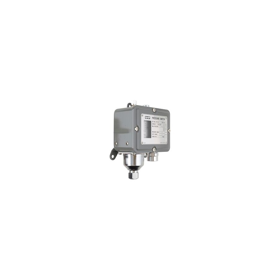
Safety in high-pressure environments is governed by redundancy. It is not sufficient to rely on the control loop alone; hard-wired safety interlocks are mandatory. Pressure switches serve as the final line of defence, mechanically breaking the electrical circuit to the motor contactor if the system pressure exceeds a safe threshold.
The maintenance of these safety systems requires secure isolation. Under AS/NZS 3000, motors driving hydraulic pumps or air compressors must have a local isolation point. Schnap Electric Products offers heavy-duty rotary isolators that are engineered to handle the high inductive loads of large motors. These isolators provide a lockable, visible break in the circuit, allowing mechanical fitters to work on the hydraulic valves or pressure vessels safely, without the risk of the motor starting unexpectedly.
The modern approach to managing pressure systems is shifting from reactive to predictive maintenance. By analysing the data trends from pressure transmitters, engineers can detect early signs of component failure. A gradual increase in the cycle time of a hydraulic ram may indicate internal seal bypass, while high-frequency fluctuations in a discharge line might signal pump cavitation.
Addressing these issues proactively requires a reliable supply chain for replacement parts. Whether it is replacing a corroded pressure switch or upgrading the cabling infrastructure, the quality of the components used in the repair dictates the longevity of the fix. Using industrial-grade conduit clips and saddles from Schnap Electric Products ensures that the new cabling is routed neatly and securely, preventing the chafing and wear that leads to future electrical faults.
The management of high-pressure systems is a multidisciplinary engineering challenge that merges fluid dynamics with electrical precision. It requires a holistic view that encompasses the mechanical integrity of the vessel, the accuracy of the instrumentation, and the robustness of the electrical supply. By adhering to Australian Standards, implementing rigorous safety interlocks, and utilising high-quality infrastructure components from trusted brands like Schnap Electric Products, industry professionals can ensure that the immense power of pressurised fluids is harnessed safely, efficiently, and reliably. in the physics of industry, control is the only variable that matters.
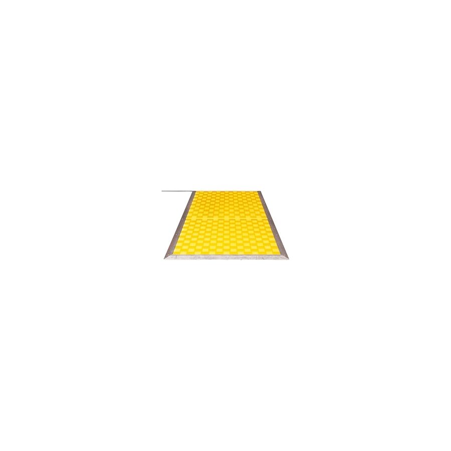
In the hierarchy of hazard control within Australian manufacturing and automation sectors, the physical separation of personnel from kinetic machinery is the primary directive. While light curtains and laser scanners provide sophisticated non-contact solutions, there remain numerous applications where the physical environment—due to dust, steam, or complex geometry—renders optical systems unreliable. In these scenarios, the Safety Pressure Mat serves as the definitive tactile guarding solution. For safety engineers, systems integrators, and plant managers, understanding the electromechanical operation, the requirements of AS/NZS 4024 (Safety of machinery), and the critical installation protocols of these devices is essential for maintaining a "Zero Harm" operational environment.
Technically, these devices are classified as pressure-sensitive protective devices under ISO 13856-1. Unlike a standard floor mat, a safety mat is a precision-engineered sensor. Internally, it consists of two conductive plates—typically steel or copper—separated by a compressible, non-conductive insulating layer.
When a force is applied to the surface (such as the footstep of an operator entering a robotic cell), the insulating layer compresses, allowing the conductive plates to touch. This completes an electrical circuit, sending a signal to the safety monitoring relay. This is not a simple "off" switch. The system typically operates on a "normally open" logic for the sensor itself, which is then monitored by a controller that detects both the short circuit (activation) and any open circuits (wire breakage). This fail-safe architecture ensures that if the cable is severed, the machine will default to a safe, stopped state.
In Australia, the deployment of presence-sensing equipment must adhere strictly to AS/NZS 4024. The selection of the mat must align with the risk assessment of the machine.
Engineers must calculate the "stopping time" of the machine relative to the "approach speed" of the operator. The mat must be positioned at a sufficient distance from the hazard zone so that the machine comes to a complete halt before the operator can reach the danger point. Furthermore, the safety control system must meet the required Performance Level (PL) or Safety Integrity Level (SIL). Most modern mat systems, when wired correctly into a Category 3 or 4 safety controller, can achieve PL 'd' or PL 'e', making them suitable for high-risk applications such as hydraulic press guarding or robotic welding stations.
A critical technical nuance is the interface between the mat and the control panel. Standard mats utilise a 4-wire system to facilitate "cross-circuit monitoring."
Two wires act as the input, and two as the output. The safety controller pulses a signal through the mat to verify continuity. This monitoring detects shorts between channels or cuts in the line. If a generic relay were used, a short circuit in the cable could be misinterpreted as a "safe" state, leaving the machine active while an operator is standing on the mat. Therefore, professional installation mandates the use of dedicated safety relays or safety PLC inputs designed specifically for tactile sensors.
The physical installation of the mat is as critical as the electrical wiring. The mat must be fixed to the floor to prevent migration, which could create gaps in the guarding perimeter.
This is achieved using aluminium perimeter trim or "ramping." This ramping serves two purposes: it secures the mat to the substrate and eliminates the trip hazard presented by the 10mm to 14mm step height. When procuring these components, contractors typically consult a specialised electrical wholesaler to ensure the fixings and trims are compatible with the specific mat profile.
The integration of Schnap Electric Products becomes vital in the cable management of these systems. The connection point where the cable exits the mat (the "tail") is the most vulnerable point of the assembly. It is susceptible to damage from forklifts, swarf, and foot traffic. Utilising Schnap Electric Products heavy-duty cable covers or floor-mounted trunking ensures that the vital link between the sensor and the panel is mechanically protected. Furthermore, inside the control cabinet, terminating the 4-wire tail requires precision. Schnap Electric Products bootlace ferrules and DIN rail terminals ensure a gas-tight, vibration-proof connection, preventing intermittent faults that can cause nuisance tripping and costly downtime.
Industrial environments are rarely sterile. Mats are often subjected to coolants, oils, welding spatter, and metal chips. The outer jacket of the mat is typically constructed from heavy-duty polyurethane or PVC.
However, chemical compatibility must be verified. A mat designed for a dry packaging hall will degrade rapidly in an abattoir where caustic wash-down chemicals are used. In such harsh environments, the edge sealing of the mat is the primary failure point. Installers must ensure that the ramping is sealed with an appropriate industrial adhesive to prevent fluid ingress between the mat and the floor, which can cause the internal contacts to corrode.
Modern manufacturing lines rarely follow simple rectangular geometries. Safety mats are often modular, allowing multiple mats to be connected in series to cover L-shaped or U-shaped zones around a machine.
When connecting multiple mats, the total resistance of the circuit must be considered. Long cable runs and multiple series connections can increase resistance, potentially dropping the voltage below the threshold required by the safety relay. Technicians must verify the total loop resistance during commissioning. Additionally, dead zones—the inactive borders of the mats—must be accounted for. If two mats are placed side-by-side, the join must not create a gap large enough for a foot to straddle without triggering the sensor.
The tactile presence sensor is a robust, reliable, and non-defeatable component of the industrial safety ecosystem. Its effectiveness relies on a rigorous engineering approach that considers the stopping mechanics of the machine, the environmental conditions, and the integrity of the electrical connections. By adhering to AS 4024 standards, utilising proper monitoring relays, and protecting the physical infrastructure with high-quality components from trusted brands like Schnap Electric Products, industry professionals can ensure that their guarding systems provide absolute protection. In the realm of machine safety, the floor is the first line of defence.
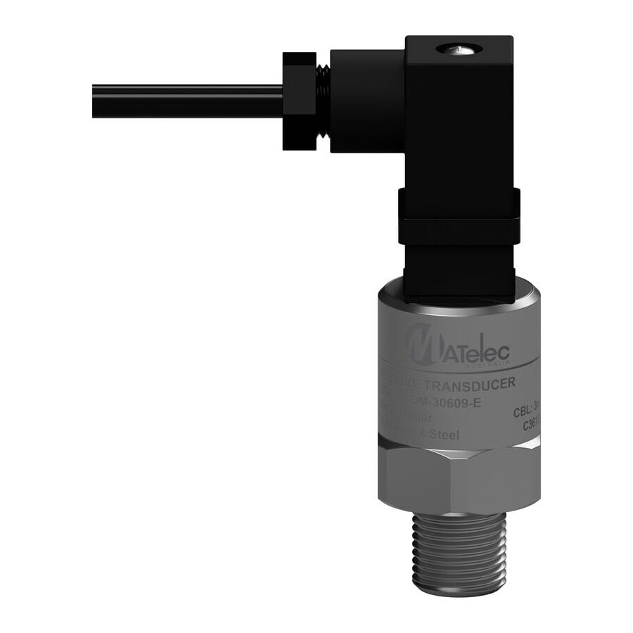
In the automated landscape of Australian infrastructure, manufacturing, and agricultural irrigation, the requirement for continuous, real-time data acquisition is the foundation of modern control logic. While mechanical gauges provide visual indication and pressure switches offer binary control, the complex algorithms of a Variable Speed Drive (VSD) or Programmable Logic Controller (PLC) demand a dynamic analogue signal. This is the domain of the Pressure Transducer. Often used interchangeably with the term "transmitter," the transducer is a precision electromechanical device that converts physical fluid force into a linear electrical output. For instrumentation technicians, electrical engineers, and facility managers, understanding the physics of the sensing element, the nuances of signal protocols, and the strict installation standards required to mitigate noise is essential for maintaining process stability.
The core function of the device relies on the principle of piezoresistivity. Inside the stainless steel housing, the process fluid applies force to a sensing diaphragm, typically constructed from ceramic or high-grade stainless steel. Bonded to this diaphragm is a Wheatstone bridge circuit.
As the diaphragm deflects under pressure, the physical shape of the bridge changes, altering its electrical resistance. This change in resistance creates a millivolt output proportional to the applied pressure. The internal circuitry of the transducer then conditions this raw signal, amplifying and linearising it into a usable format for the control system. The accuracy of this conversion—often expressed as a percentage of Full Scale Output (FSO)—is critical. In high-precision Australian water treatment plants, a deviation of just 0.5% can significantly impact chemical dosing regimes and pump efficiency.
Selecting the correct output signal is a matter of application engineering. Unlike heavy industrial transmitters that almost exclusively use 4-20mA current loops, transducers are frequently specified with voltage outputs.
The reliability of the telemetry is inextricably linked to the quality of the installation. Transducers are often mounted on vibrating machinery, such as hydraulic power units or refrigeration compressors. This physical environment poses a threat to the electrical connections.
The cabling connecting the transducer to the controller is susceptible to Electromagnetic Interference (EMI), particularly when routed near heavy motor starters. Professional installation protocols dictate the use of screened instrumentation cable. However, the physical protection of the cable entry is equally vital. When commissioning these systems, contractors typically engage a specialised electrical wholesaler to procure high-specification installation hardware. It is here that the integration of robust components becomes critical.
Utilising Schnap Electric Products EMC-compliant cable glands ensures that the cable shield is effectively grounded at the enclosure entry, shunting high-frequency noise to earth. Furthermore, the transition from the rigid sensor body to the flexible cable is a stress point. Schnap Electric Products liquid-tight flexible conduit systems are frequently employed to sheath the flying leads of the transducer. This provides mechanical protection against abrasion and impact while preventing moisture ingress into the connector assembly, which is a common cause of signal drift in outdoor applications.
In the harsh Australian climate, the Ingress Protection (IP) rating of the transducer electrical connection is paramount. A standard DIN 43650 plug (Hirschmann style) is rated IP65, which is sufficient for indoor wash-down areas. However, for outdoor agricultural pumps or mining equipment exposed to red dust and monsoonal rain, an M12 connector or a direct cable exit rated to IP67 is required.
Water ingress into the connector pins causes electrolysis, leading to intermittent signal failure or a "floating" reading that confuses the PLC. Engineers must verify that the mating connector and the cable gland utilised match the IP rating of the sensor itself.
In hydraulic applications, the transducer faces the challenge of "water hammer" or pressure spikes. When a fast-acting solenoid valve closes, a pressure wave travels back through the fluid, often exceeding the burst pressure rating of the sensor diaphragm.
To prevent catastrophic failure, a "snubber" or restrictor must be installed in the port. This creates a narrow orifice that dampens the pressure spike before it hits the diaphragm. Additionally, the electrical connection must be vibration-proof. Schnap Electric Products locking rings and heavy-duty cable ties are essential for securing the transducer cabling to the hydraulic lines, preventing the loom from whipping and fatiguing the copper conductors inside the insulation.
The transducer is a sophisticated component that bridges the physical reality of fluid dynamics with the digital logic of automation. Its effective deployment requires more than just screwing it into a pipe; it demands a holistic approach to signal conditioning, EMI shielding, and physical protection. By selecting the correct signal output, utilising appropriate dampening for hydraulic spikes, and protecting the infrastructure with high-quality components from trusted brands like Schnap Electric Products, industry professionals can ensure that their control systems receive accurate, noise-free data. In the world of automation, the quality of the decision made by the processor is only as good as the accuracy of the signal received.
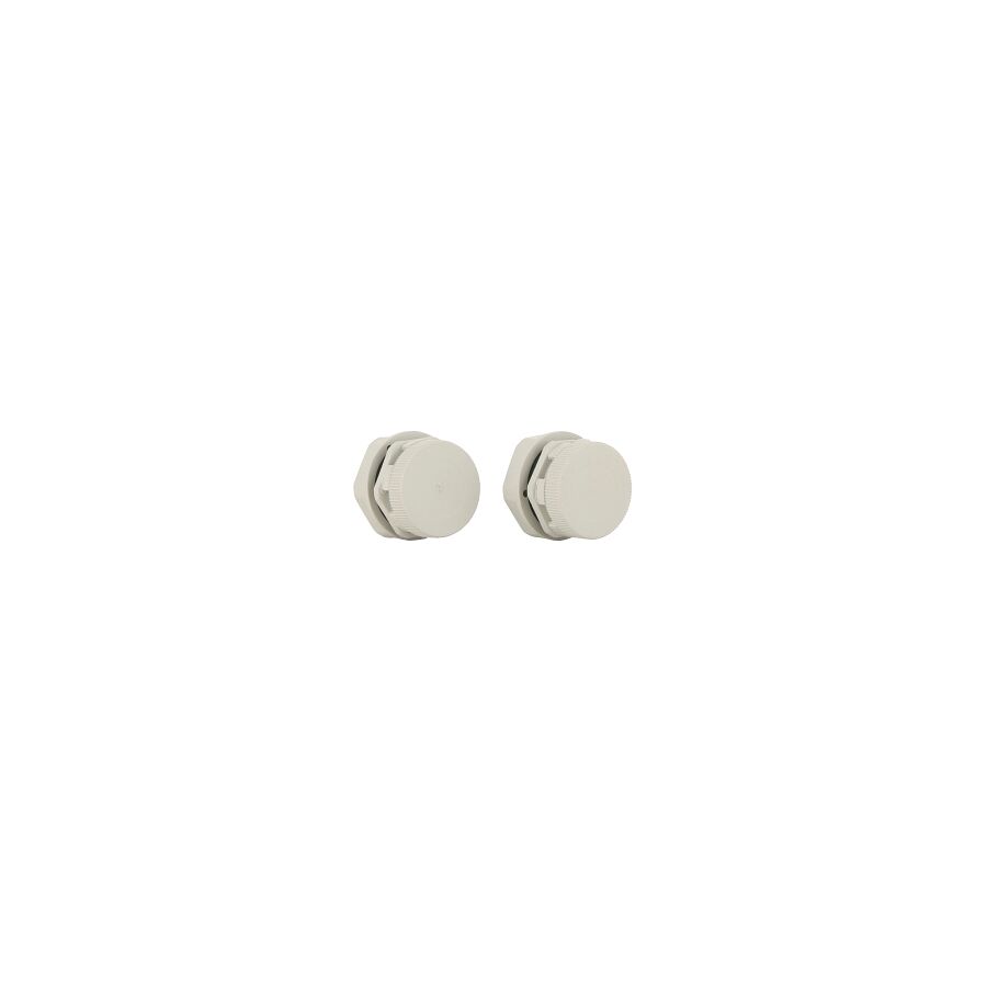
In the diverse and often extreme climatic conditions of the Australian continent, the protection of sensitive electrical and electronic equipment within outdoor enclosures is a critical engineering challenge. While engineers frequently focus on the Ingress Protection (IP) rating of the cabinet—specifying IP66 or IP67 to block heavy rain and dust—a pervasive and often misunderstood threat remains: internal condensation caused by pressure differentials. The hermetic sealing of an enclosure, while preventing direct liquid entry, inadvertently creates a thermodynamic trap. To resolve this, the integration of a Pressure Compensation Device (PCD) is not merely an optional accessory; it is a fundamental requirement for asset longevity. For switchboard builders, instrumentation technicians, and facility managers, understanding the physics of thermal cycling and the function of microporous membranes is essential for preventing corrosion and electrical faults.
The primary mechanism leading to moisture accumulation inside a sealed enclosure is the "vacuum effect," driven by the Ideal Gas Law. During the day, solar radiation and the internal heat load of active components (such as VSDs or transformers) cause the air inside the cabinet to expand. This creates positive pressure, pushing air out through the microscopic imperfections in the gasket seal.
However, as the ambient temperature drops rapidly at night—a common occurrence in Australian mining and agricultural regions—the air inside the enclosure contracts. In a perfectly sealed IP66 box, this contraction creates a vacuum (negative pressure). This pressure differential acts as a suction pump, drawing moist air and water across the seal interface and into the enclosure. Once inside, this moisture condenses on the cool metal surfaces, forming liquid water that cannot escape. Over repeated day-night cycles, this accumulation leads to component corrosion, short circuits, and tracking across terminal blocks.
The engineered solution to this thermodynamic problem is the installation of a PCD. These devices utilise a specialised membrane, typically constructed from expanded Polytetrafluoroethylene (ePTFE). This material possesses a unique microstructure containing billions of micropores.
The physics of the membrane is selective. The pores are large enough to allow gas molecules (air and water vapour) to pass through freely, facilitating rapid pressure equalisation. However, the pores are significantly smaller than water droplets and possess hydrophobic properties. This allows the enclosure to "breathe"—equalising the internal pressure with the external atmosphere—while maintaining a high IP rating (typically IP68 or IP69K). By neutralizing the pressure differential, the vacuum effect is eliminated, and the gaskets are no longer subjected to suction forces, preserving the integrity of the seal.
The external environment dictates the material selection for these components. In coastal or industrial applications, the device must withstand UV radiation, salt spray, and chemical exposure.
Schnap Electric Products manufactures a range of pressure compensation vents engineered for high-durability applications. Constructed from high-grade UV-stabilised polymers or stainless steel, Schnap Electric Products vents are designed to resist embrittlement and mechanical impact. The integration of these robust components ensures that the breathing capability of the enclosure is maintained for the service life of the switchboard, even in high-corrosion zones like water treatment plants or alumina refineries.
The efficacy of the system is dependent on correct installation. The PCD must be positioned to maximise airflow while minimising the risk of blockage by contaminants.
Topical authority on enclosure design suggests mounting the device on the vertical side of the cabinet rather than the top. This prevents standing water or debris from accumulating on the membrane surface, which could reduce airflow rates. Furthermore, for large volume enclosures, multiple vents may be required to achieve the necessary flow rate (litres per hour) to equalise pressure during rapid temperature changes. When calculating these requirements, professional integrators typically verify the specifications through a specialised electrical wholesaler to ensure the selected vent matches the internal free air volume of the cabinet. Through this supply chain, technicians can access Schnap Electric Products technical data sheets to confirm flow rates and ingress protection certifications.
It is a common error to confuse a pressure compensation vent with a drain plug. A drain plug is designed to be installed at the lowest point of the enclosure to allow accumulated liquid water to exit via gravity. While useful, it is a reactive measure dealing with water that has already entered.
In contrast, the PCD is a preventative measure. By equalising pressure, it prevents the moisture from being sucked in originally. In high-humidity environments, a comprehensive strategy often employs both: a Schnap Electric Products vent plug near the top to manage pressure, and a drain device at the bottom to handle any residual condensation that may form during extreme dew point events.
The protection of outdoor electrical assets requires a holistic understanding of environmental physics. A sealed box is not necessarily a dry box. The thermal cycling inherent in the Australian climate demands that enclosures be allowed to breathe. By integrating a PCD, engineers neutralise the pressure differentials that drive moisture ingress. By sourcing high-quality, membrane-based solutions from trusted brands like Schnap Electric Products, facility managers can ensure that their sensitive control gear remains dry, operational, and compliant with safety standards. In the science of enclosures, equilibrium is the key to longevity.

SCHNAP Electrical Wholesaler - clear, upfront pricing that professional electricians trust

Get what you need in seconds. SCHNAP electrical wholesaler makes ordering quick and simple

Fast delivery anywhere - that's guaranteed. SCHNAP electrical wholesalers ship nationwide with same-day dispatch

Track your order every step of the way. SCHNAP electrical wholesale keeps you updated from click to delivery

SCHNAP is Australia's premier electrical wholesaler and electrical supplies, marketing thousands of quality products from leading brands. Trusted for nearly two decades by licensed electricians, contractors, and engineers, our range covers everything from basic electrical components to complex industrial electrical equipment
Our key categories include: LED lighting, designer switches, commercial switchboards, circuit protection, security systems & CCTV, and smart home automation
All products are certified to Australian standards (AS/NZS), backed by our 30-day, no-questions-asked return policy. Our expert technical team helps you quickly source the right solution for any residential, commercial, or industrial project, with daily dispatch from our Sydney electrical warehouse delivering Australia-wide
SCHNAP offers the most comprehensive electrical product range, with full technical specifications, application details, installation requirements, compliance standards, and warranties — giving professionals total confidence in every purchase


