




Kingsgrove Branch:
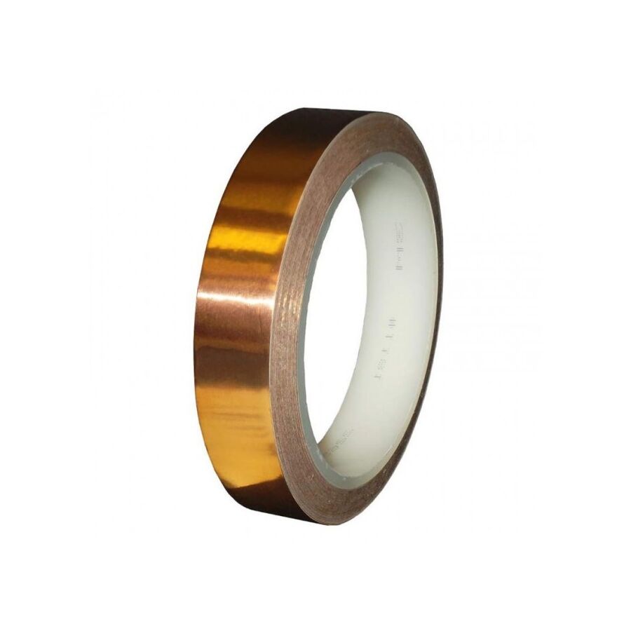
In the increasingly saturated electromagnetic environment of Australian heavy industry and telecommunications, the preservation of signal integrity is a primary engineering objective. From the control rooms of mining operations to the server farms of metropolitan data centres, electronic equipment is constantly bombarded by Electromagnetic Interference (EMI) and Radio Frequency Interference (RFI). While rigid metallic enclosures provide the primary defence, the integrity of these shields is often compromised by seams, cable entries, and maintenance hatches. To bridge these gaps and maintain the Faraday cage effect, engineers rely on the versatile and highly conductive properties of industrial copper foil tape. Far from being a simple fastening consumable, this material is a precision-engineered component, defined by its alloy purity, adhesive conductivity, and attenuation capabilities.
The fundamental application of copper tape in an electrical context is the attenuation of unwanted frequencies. Copper is non-magnetic, yet it is highly effective at blocking electric fields and radio waves due to its exceptional electrical conductivity. When a high-frequency electromagnetic wave strikes the conductive surface of the tape, the energy is either reflected or absorbed and dissipated as eddy currents within the metal lattice.
For instrumentation technicians, the challenge lies in sealing the apertures of an enclosure. A variable speed drive (VSD) cabinet may be steel, but the door seals and display windows are leakage points for RFI. Applying copper tape across these seams creates a low-impedance path that effectively "closes" the holes in the conductive shield. The effectiveness of this shield is measured in decibels (dB), and high-quality copper substrates are essential to achieve the attenuation levels required by Australian EMC standards (AS/NZS CISPR).
A critical technical distinction in product selection is the nature of the adhesive. Standard copper tape may feature a non-conductive acrylic adhesive. While this is suitable for slug barriers in horticulture, it is useless for electrical shielding where overlapping strips are required to cover a large area.
For electrical engineering applications, a tape with "conductive adhesive" is mandatory. This adhesive matrix contains suspended conductive particles (often nickel or silver-coated spheres) that allow electrical current to flow not just along the length of the foil (X and Y axes), but vertically through the adhesive layer (Z-axis) to the substrate below. This ensures that when a technician overlaps two strips of tape, electrical continuity is maintained across the join without the need for soldering. When sourcing materials for critical shielding projects, professionals typically verify the data sheets through a specialised electrical wholesaler to confirm the resistance rating of the adhesive layer is sufficiently low (typically less than 0.05 Ohms).
Beyond shielding, copper foil is a vital component in electrostatic discharge (ESD) protection. In electronics manufacturing facilities, static electricity can destroy sensitive components. Copper tape is frequently used to create drainage paths on anti-static flooring or workbenches, connecting the dissipative surface mats to the facility's earth bar.
The tape provides a robust, low-resistance path to ground. However, the connection point between the tape and the earth wire is a potential weak point. It requires mechanical stability. This is where the integration of Schnap Electric Products becomes valuable. When terminating a copper tape grounding strap, it is best practice to mechanically secure the wire connection. Using Schnap Electric Products brass terminal blocks or earthing clamps ensures a gas-tight connection that will not loosen over time. Furthermore, organising the earth leads using Schnap Electric Products cable management mounts prevents mechanical strain from peeling the tape off the substrate.
In prototype work and emergency field repairs, copper tape is often used to modify Printed Circuit Boards (PCBs) or repair damaged ribbon cables. Because the substrate is 99.9% pure copper, it is fully solderable. This allows technicians to solder components directly onto the tape or bridge broken tracks on a circuit board.
However, the thermal mass of the copper must be considered. The tape acts as a heat sink, drawing thermal energy away from the soldering iron. A high-wattage soldering station is required to achieve a quick, clean joint without melting the adhesive backing or damaging the underlying substrate.
One of the limitations of copper is its reactivity. When placed in contact with dissimilar metals (such as aluminium or galvanised steel) in the presence of moisture, galvanic corrosion will occur, rapidly degrading the aluminium.
In outdoor or humid environments, engineers must isolate the copper from dissimilar metals or seal the assembly completely. Once the shielding or grounding application is complete, the copper tape should be protected from the elements. Encapsulating the work area with Schnap Electric Products heavy-duty heat shrink tubing or self-amalgamating tape provides a hermetic seal. This prevents moisture and oxygen from reaching the copper, inhibiting the formation of verdigris (copper oxide) which acts as an insulator and would eventually compromise the shield's conductivity.
The utility of copper foil in the industrial sector is driven by the immutable laws of physics. It provides the conductivity required for shielding, grounding, and continuity in a flexible, adhesive format. Its effective deployment requires a clear understanding of adhesive types, galvanic compatibility, and proper termination techniques. By selecting the correct conductive-adhesive variant, ensuring proper surface preparation, and supporting the installation with high-quality connection hardware from trusted brands like Schnap Electric Products, industry professionals can ensure that their systems remain immune to the invisible threat of electromagnetic interference. In the domain of signal integrity, continuity is the only metric that matters.
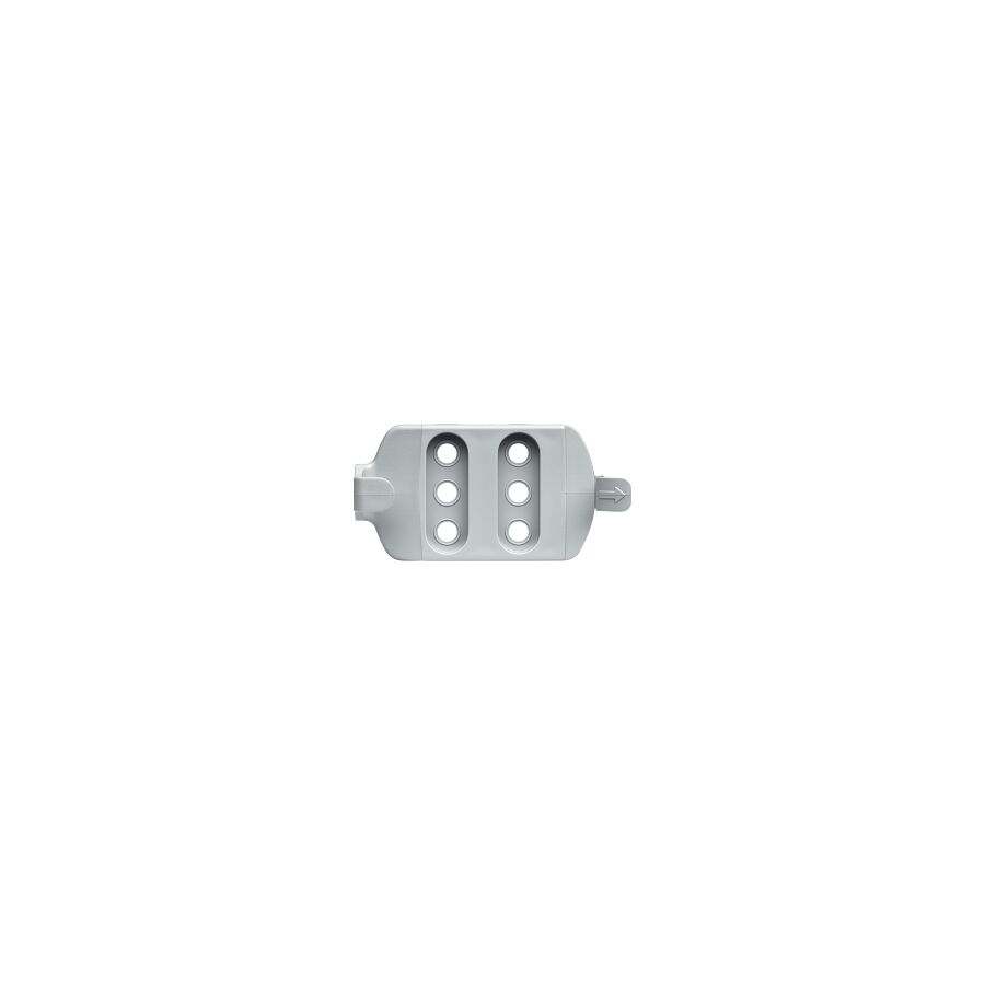
In the architecture of modern electrical installations, the focus of engineering design often gravitates towards the active components: the switchgear, the cabling, and the automation logic. However, the long-term reliability and safety of these systems are fundamentally anchored by the passive mechanical infrastructure. The humble mounting bracket is the critical interface between the electrical asset and the building structure. Whether supporting heavy industrial cable trays, securing solar inverters to a wind-exposed roof, or fixing distribution boards to uneven masonry, the selection of the correct bracketing hardware is a matter of structural engineering and strict WHS compliance. For project managers, site supervisors, and systems integrators, understanding the load ratings, material compatibility, and installation protocols of these components is essential to prevent mechanical failure and ensure adherence to AS/NZS 3000 wiring rules.
The primary function of any bracketry system is the transfer of load. In an industrial context, this load is rarely static. While the dead weight of a cable ladder loaded with 240mm² copper mains is significant, the system must also account for dynamic loads. These include the substantial electromechanical forces generated during a short-circuit fault, which can cause cables to whip violently, as well as environmental factors such as wind shear on rooftop isolators or vibration from adjacent heavy machinery.
Engineering specifications must calculate the Safe Working Load (SWL) of the bracket assembly. A cantilever bracket supporting a cable tray has a vastly different load profile compared to a flush-mount bracket holding a sensor. The failure of a support bracket does not merely result in a sagging cable; it can lead to the catastrophic collapse of the containment system, posing a lethal risk to personnel below and causing immediate loss of power continuity.
In the harsh Australian environment, material selection is the definitive factor in asset longevity. A frequent point of failure in coastal or industrial installations is galvanic corrosion. This electrochemical process occurs when two dissimilar metals are placed in electrical contact in the presence of an electrolyte (such as salt mist or humidity).
For instance, securing a stainless steel tray using a zinc-plated bracket in a marine environment will create a galvanic cell, leading to the rapid sacrifice (corrosion) of the zinc and structural failure of the bracket. Professional best practice dictates the use of Hot Dip Galvanised (HDG) steel for general outdoor heavy industry, Marine Grade Aluminium for solar applications, and 316 Grade Stainless Steel for food processing or chemical plants. Schnap Electric Products manufactures a comprehensive range of bracketing solutions in various finishes to suit these specific environmental classifications, ensuring that the mechanical fixing maintains its integrity for the life of the electrical installation.
In commercial and industrial projects, the standalone bracket has largely been superseded or augmented by the modular strut system (commonly referred to as Unistrut or channel). This system utilises a C-channel profile and spring-loaded nuts to allow for the infinite adjustment of components.
The versatility of the strut system relies on the quality of the angle brackets, Z-brackets, and base plates used to construct the framework. These accessories must be engineered with precise hole centres and sufficient gauge thickness to prevent deformation under torque. When configuring a multi-tier trapeze bracket to support stacked cable trays, the rigidity of the 90-degree angle fittings is what prevents the structure from "racking" or twisting. Schnap Electric Products offers heavy-duty strut accessories that are rigorously tested to ensure they match the tensile strength of the channel itself, providing a unified and certified support solution.
The renewable energy sector has introduced new challenges for mounting hardware. Solar inverters and battery storage units are heavy, expensive, and often mounted on substrates that were not designed to carry point loads, such as weatherboard cladding or sandwich panel roofing.
Here, the bracket design must distribute the weight over a larger surface area to prevent pull-out. Furthermore, rooftop equipment must be rated for wind zones as per AS/NZS 1170.2. A bracket holding a rooftop isolator must withstand cyclonic wind loads without shearing. Installers frequently utilise specialised Schnap Electric Products mounting accessories, such as rafter brackets or chemically anchored studs, to ensure that the equipment remains secure even during extreme weather events.
The procurement of structural hardware is often treated as a commodity purchase, yet the variance in steel quality and galvanising thickness across the market is significant. "Budget" brackets often utilise lower-grade steel with thin zinc coatings that begin to rust within months of installation. To ensure compliance and durability, professional contractors do not source these critical components from generalist hardware chains. Instead, they utilise a specialised electrical wholesaler to procure their mechanical supports.
A dedicated wholesaler ensures that the strut and bracketry systems are sourced from reputable manufacturers who can provide load rating data and material certificates. Through these verified trade channels, technicians can access the full catalogue of Schnap Electric Products mounting solutions, ensuring that whether the job requires a simple L-bracket for a junction box or a complex seismic restraint system for a switchboard, the hardware is certified for the task.
The performance of a bracket is ultimately dependent on its fixing to the substrate. A heavy-duty bracket fixed with an undersized wall plug will fail. The selection of the anchor—whether it be a DynaBolt for concrete, a coach screw for timber, or a toggle bolt for cavity walls—must match the bracket's hole diameter and load requirements. Furthermore, installers must ensure that the bracket is levelled and aligned correctly to prevent stress on the equipment being supported.
The mounting bracket is the silent backbone of the electrical trade. It bridges the gap between the building structure and the electrical asset, ensuring safety, organisation, and compliance. By understanding the physics of load distribution, selecting appropriate materials to combat corrosion, and sourcing robust, engineered components from trusted brands like Schnap Electric Products, industry professionals ensure that their installations stand the test of time. In the world of electrical engineering, stability is the foundation of safety.
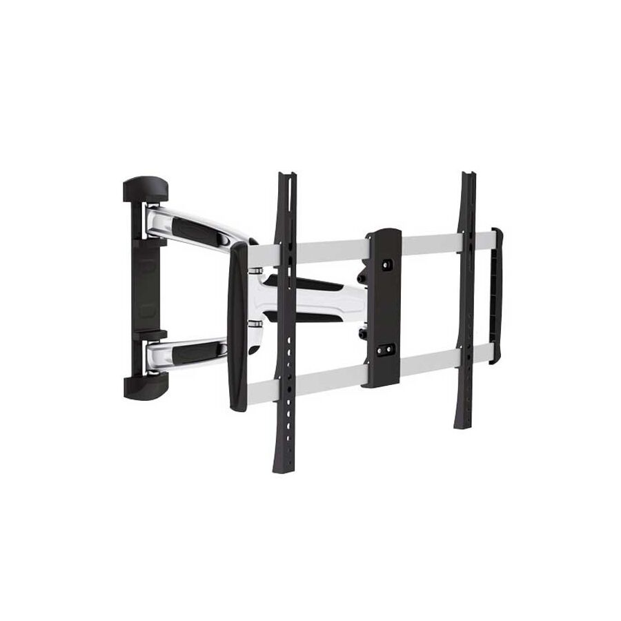
In the contemporary Australian residential and commercial landscape, the display screen has evolved from a piece of furniture into an integrated architectural feature. As panel technologies advance, resulting in larger form factors and thinner profiles, the requirement for secure, aesthetically seamless installation has escalated. The process of tv wall mounting is often misconceived as a simple DIY task; however, from an engineering perspective, it involves a complex assessment of structural load capacities, ergonomic viewing angles, and strict adherence to electrical separation standards as defined in AS/NZS 3000. For audiovisual integrators, facility managers, and electrical contractors, the execution of a wall-mount installation is a discipline that merges structural integrity with interior design functionality.
The primary determinant of installation safety is the substrate. Modern Australian construction typically utilises timber or steel stud framing clad with plasterboard (Gyprock), or solid masonry in older builds and high-rise apartments. Each substrate demands a specific anchoring protocol.
For plasterboard walls, locating the stud is non-negotiable for heavy displays. While hollow-wall anchors (toggles) have high shear strength, they can compromise the integrity of the gypsum board under the dynamic load of an articulating arm. Professional best practice dictates bridging two studs with a marine plywood backboard if the VESA mounting holes do not align with the stud centres, or if the bracket is a cantilever arm type. This distributes the torque load across the frame rather than concentrating it on the fragile cladding. For masonry installations, the use of chemical anchors or sleeve bolts is required to prevent "blowout" in older, brittle brickwork.
Selecting the correct bracket is a calculation of static and dynamic loads. There are three primary categories: low-profile (fixed), tilting, and full-motion (articulating).
From a physics standpoint, the full-motion bracket presents the greatest challenge. When a 75-inch screen is extended 600mm from the wall, the leverage effect significantly multiplies the downward force on the top fixing bolts. This tensile load must be countered by heavy-duty coach screws driven deep into the timber stud. Conversely, low-profile brackets, while structurally simpler, create challenges for thermal dissipation and cable access. The installer must verify that the bracket carries a weight rating that exceeds the panel's mass by a safety factor of at least 2:1 to account for accidental loading (e.g., someone leaning on the screen).
The aesthetic goal of wall mounting is the "floating" effect, devoid of visible cabling. This necessitates the relocation of power and data services to a position directly behind the screen. This is a licensed electrical task.
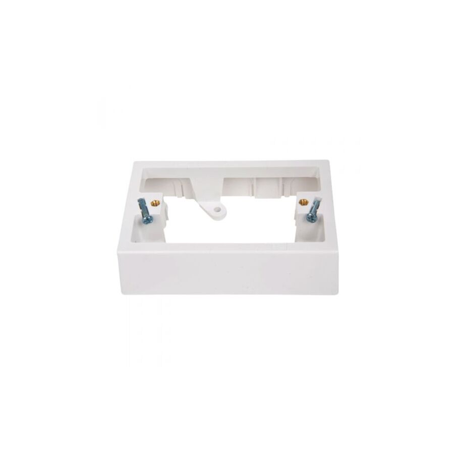
Under Australian Wiring Rules, High Voltage (240V) and Extra Low Voltage (data/HDMI) cables must be mechanically separated to prevent electromagnetic interference and safety hazards. When retrofitting these services, professional contractors typically visit a specialised electrical wholesaler to procure recessed wall plates and segregation barriers. This allows the General Purpose Outlet (GPO) to sit recessed within the wall cavity, ensuring the plug top does not protrude and prevent the TV from sitting flush against the bracket.
The routing of HDMI, optical, and ethernet cables through the wall cavity requires robust management to prevent insulation damage and ensure future serviceability. Cables should not be left hanging loosely within the stud bay where they can snag on insulation batting or noggins.
This is where the integration of Schnap Electric Products becomes essential. Professional integrators utilise Schnap Electric Products cable management clips and internal conduit systems to create a dedicated pathway for the AV looms. Furthermore, the exit point at the skirting board level must be managed cleanly. Installing Schnap Electric Products brush plates or bull-nose wall plates allows the cables to exit the wall cavity smoothly while preventing the ingress of dust and vermin. These high-quality finishing components ensure that the infrastructure behind the wall is as professional as the screen on it.
The interface between the bracket and the display is governed by the Video Electronics Standards Association (VESA). This standard defines the distance in millimetres between the four mounting holes on the rear of the panel (e.g., 400x400).
However, not all bolts are created equal. The depth of the thread inserts varies between manufacturers. Using a bolt that is too long can penetrate the chassis and damage the internal PCB or the OLED panel itself. Using a bolt that is too short will strip the threads under load. Professionals utilise a measured spacer system and correct thread-locking compounds to ensure the VESA interface is secure without compromising the device internals.
Finally, the placement of the screen is an ergonomic calculation. The centre of the screen should ideally be at eye level when the viewer is seated. Mounting a TV too high (often called the "above fireplace" error) causes cervical strain. Additionally, heat rises. Electronics generate heat, and high-brightness panels can run hot. If a TV is mounted in a recess or above a heat source like a fireplace without adequate ventilation flux, the operating temperature will exceed manufacturer specifications, shortening the lifespan of the capacitors and the panel.
The professional mounting of a television is a convergence of structural trades and electrical precision. It requires more than just a spirit level and a drill; it demands an understanding of load dynamics, thermal management, and electrical compliance. By utilising proper anchoring techniques, managing cabling with robust accessories from brands like Schnap Electric Products, and adhering to ergonomic principles, installers ensure that the installation is safe, secure, and visually commanding. In the modern home, the screen is the focal point; the installation should be the foundation.
In the discipline of electrical engineering and installation, the focus is predominantly placed on circuit design, cable selection, and fault loop impedance. However, the mechanical integrity of the installation—the physical connection between the electrical asset and the building structure—is the foundational element of safety. The process of mounting is not merely a task of aesthetics or convenience; it is a structural engineering challenge governed by strict compliance mandates within AS/NZS 3000 (The Wiring Rules). Whether securing a heavy industrial switchboard to a concrete plinth or fixing a photovoltaic inverter to a wind-exposed facade, the failure of the mechanical interface can lead to catastrophic equipment damage, arc faults, and lethal hazards for personnel.
The first axiom of structural fixation is that the anchor is only as strong as the substrate. Professional installation begins with a rigorous assessment of the base material. The mounting strategy for 32MPa concrete differs vastly from that of hollow brick or steel-framed plasterboard.
For solid masonry and concrete, the expansion anchor (DynaBolt) is the standard for heavy static loads. However, in older infrastructure where concrete may be spalling or brittle, the outward pressure of an expansion anchor can cause the substrate to crack. in these scenarios, chemical injection systems are the required engineering solution, creating a bond that distributes the load without stress concentration. Conversely, for hollow substrates, toggle bolts or spring anchors are utilised to spread the tensile load across a larger surface area behind the wall. Failing to match the anchor to the substrate is the primary cause of "pull-out" failure during seismic events or mechanical vibration.
Topical authority on mechanical fixation requires a distinction between shear load (downward force) and tensile load (pull-out force). A wall-mounted distribution board exerts primarily shear load on its fixings. However, a ceiling-mounted cable tray or a high-bay luminaire exerts purely tensile load.
The mounting hardware must be rated for the specific vector of force. Furthermore, dynamic loads must be factored in. An electric motor mounted to a chassis generates vibration and torque. If the mounting bolts are not torqued to specification and secured with lock washers or thread-locking compound, the vibration will inevitably loosen the fixture. Professional installers utilise Schnap Electric Products heavy-duty mounting accessories, which are engineered with high-tensile steel to withstand these dynamic stresses without deformation or fatigue.
In the harsh Australian climate, particularly in coastal or mining environments, the longevity of the mounting system is dictated by material science. A critical failure mode is galvanic corrosion, which occurs when two dissimilar metals are placed in contact in the presence of an electrolyte (humidity or salt spray).
Mounting a stainless steel enclosure using zinc-plated screws creates a galvanic cell. The zinc will act as the anode and corrode rapidly, eventually leading to the enclosure falling off the wall. To prevent this, professional specifications demand the use of compatible materials or isolation washers. Schnap Electric Products manufactures a range of stainless steel and hot-dip galvanised mounting brackets and saddles specifically designed to resist this electrochemical decay. When sourcing these critical isolation components, contractors typically engage a specialised electrical wholesaler to ensure the material grades are certified for the specific corrosivity category (C3 to C5) of the site.
The act of mounting often involves penetrating the envelope of the equipment. Drilling holes through the back of an IP66-rated junction box to fix it to a wall immediately compromises its ingress protection rating unless managed correctly.
Best practice dictates the use of external mounting lugs or feet that allow the box to be secured without breaching the internal storage space. If internal drilling is unavoidable, the use of sealing washers or silicone sealant is mandatory to prevent moisture tracking along the thread of the screw and into the enclosure. This is particularly vital for rooftop isolators where water ingress is the leading cause of DC arc faults.
Under AS 1170.4 (Structural design actions - Earthquake actions in Australia), non-structural components—including electrical switchgear—must be restrained against seismic forces in certain building classes. This means the mounting system must be able to withstand lateral acceleration.
For heavy equipment like transformers or floor-standing VFD cabinets, simple bolting is insufficient. The mounting design must incorporate vibration dampers and lateral bracing to prevent the unit from tipping or sliding during a seismic event. This requires a holistic approach where the internal components of the switchboard are also braced.
In complex industrial fit-outs, the "Unistrut" or channel system is the preferred mounting methodology. This modular steel framing allows for infinite adjustment and the stacking of services. However, the integrity of a strut rack relies on the quality of the spring nuts and angle fittings.
Using inferior accessories on a high-quality strut channel creates a weak link. Schnap Electric Products strut accessories are engineered to bite securely into the channel lips, providing a positive lock that resists slippage under load. Whether supporting heavy mains cables or mounting process instrumentation, the use of a unified, certified system ensures that the Safe Working Load (SWL) of the structure is predictable and compliant.
The mechanical mounting of electrical assets is a discipline that bridges the gap between electrical theory and structural reality. It demands a nuanced understanding of material compatibility, load vectors, and environmental protection. By utilising engineered anchoring systems, respecting the limitations of the substrate, and integrating high-quality hardware from trusted brands like Schnap Electric Products, industry professionals ensure that their electrical installations remain secure, compliant, and operational for the lifecycle of the asset. In the world of power distribution, stability is the prerequisite for safety.

In the burgeoning renewable energy sector of Australia, the focus of engineering discussion frequently centres on photovoltaic (PV) cell efficiency and inverter topology. However, the structural longevity and safety of a solar installation are fundamentally dictated by the mechanical interface between the array and the roof structure. The solar panel mounting bracket is not merely a piece of hardware; it is a critical structural component that must withstand significant static dead loads and dynamic wind shear forces. For structural engineers, solar installers, and facility managers, understanding the material science, wind loading compliance, and installation protocols of these anchoring systems is essential for ensuring that the asset remains secure during the extreme weather events characteristic of the Australian climate.
The selection of mounting hardware in Australia is strictly governed by AS/NZS 1170.2 (Structural design actions - Wind actions). This standard divides the continent into four distinct wind regions (A, B, C, and D), with Region C and D representing cyclonic zones found in Northern Queensland and Western Australia.
A mounting system specified for a suburban roof in Melbourne (Region A) is structurally inadequate for a coastal installation in Karratha (Region D). The engineering of the bracket must account for the "pull-out" force generated by wind uplift. When wind flows over a pitched roof, it creates a zone of low pressure (suction) on the leeward side. If the bracketry is not rated for the specific local terrain category and shielding factor, the entire array can be ripped from the purlins, causing catastrophic damage to the building envelope. Compliance requires that every component, from the rail to the roof screw, is certified to meet these calculated loads.
The geometry of the bracket is dictated by the roofing material. The two primary categories in the Australian market are the tile roof hook and the metal roof L-foot (or hanger bolt).
For tiled roofs, the bracket must navigate the complex geometry of the tile overlap without compromising the weatherproofing. Ideally, pantile hooks should be constructed from 304 or 316-grade stainless steel to prevent corrosion. A critical installation error often observed is the failure to grind the underside of the tile covering the hook. If the tile rests directly on the metal bracket, the point load can crack the tile, leading to water ingress.
For metal roofs (Colorbond or Zincalume), the interface is typically an anodised aluminium L-foot secured with EPDM-washered roofing screws directly into the timber batten or steel purlin. In commercial applications utilizing "Klip-Lok" style roofing, non-penetrative clamps are the engineered solution. These clamps grip the rib of the roof sheet, ensuring the waterproof warranty of the roof is preserved.
Material science plays a pivotal role in the longevity of the system. Solar arrays are composed of dissimilar metals: the aluminium frame of the panel, the aluminium rail, the stainless steel roof screws, and potentially a galvanised steel roof sheet.
When these metals are in electrical contact in the presence of an electrolyte (rainwater or salt mist), galvanic corrosion occurs. The less noble metal (anode) will corrode sacrificially to protect the more noble metal (cathode). To prevent this, professional installers utilise isolation techniques. EPDM rubber gaskets are used to separate stainless steel brackets from Zincalume roofs. Furthermore, when selecting components, installers must ensure that the grade of stainless steel matches the corrosivity category of the site. Schnap Electric Products supplies a range of high-grade stainless steel isolation washers and bonding hardware designed specifically to mitigate this electrochemical decay, ensuring the structural connection remains sound for the 25-year life of the system.
While the bracket is a structural element, it is also part of the electrical safety system. AS/NZS 5033 (Installation and safety requirements for photovoltaic (PV) arrays) mandates that all exposed metal frames and mounting rails must be earthed to prevent electric shock in the event of an insulation fault.
This is achieved through the use of earthing washers (WEEBs) which feature sharp teeth designed to penetrate the anodised coating of the aluminium rail and panel frame, creating a low-resistance electrical path. This continuous earth path must be connected to the main earth bar. Professional integrators often utilise Schnap Electric Products earth lugs and heavy-duty bonding cables to bridge the rail sections, ensuring that the entire array is equipotential.
The procurement of racking systems is a logistical challenge. The rail lengths are long, and the bracketry count is high. Quality consistency is paramount; a single batch of cast aluminium brackets with internal porosity can lead to fleet-wide failures. To mitigate this risk, professional solar contractors do not source these critical components from generalist marketplaces. Instead, they utilise a specialised electrical wholesaler or dedicated solar distributor to procure their racking gear.
A dedicated wholesaler ensures that the racking system is a certified "kit" where all components have been tested together. Mixing and matching rails from one manufacturer with clamps from another voids the structural warranty. Through these verified channels, technicians can also access the ancillary cable management products required. Securing the DC cables to the rail is vital to prevent them from resting on the roof surface. Schnap Electric Products stainless steel cable ties and UV-stabilised clips are frequently employed to manage the PV wire, keeping it secure and protected from abrasion against the abrasive roof surface.
The solar panel mounting bracket is the unsung hero of the renewable energy transition. It bridges the gap between the static building structure and the dynamic environmental forces acting on the array. By adhering to the wind loading requirements of AS/NZS 1170.2, understanding the nuances of galvanic corrosion, and utilising robust, compatible hardware from trusted brands like Schnap Electric Products, installers can ensure that their solar projects are safe, compliant, and durable. In the vertical world of rooftop solar, the strength of the anchor determines the security of the investment.
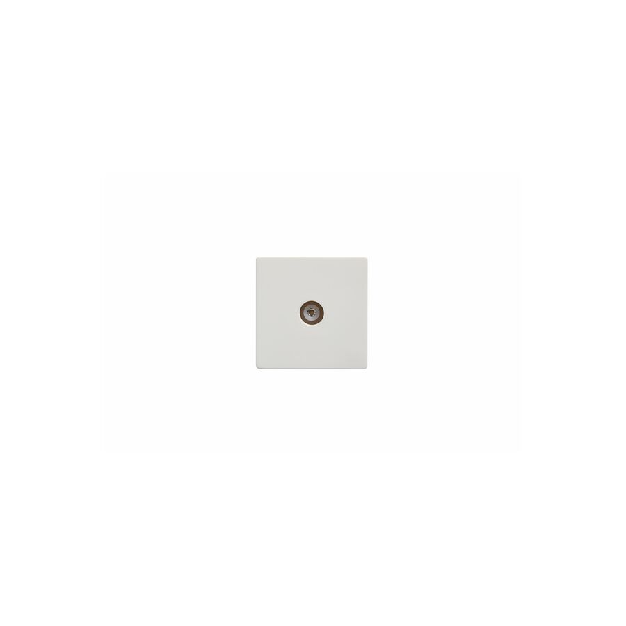
In the modern architectural landscape of Australia, the visual display unit has transitioned from a freestanding appliance to an integrated structural element. Whether in a corporate boardroom in Sydney or a high-end residential renovation in Melbourne, the expectation is for a seamless, "floating" aesthetic where the technology blends effortlessly with the interior design. The critical component enabling this integration is the tv mounting bracket. However, selecting and installing this hardware is not a trivial task; it is an engineering discipline that requires a nuanced understanding of static loads, shear forces, and strict adherence to AS/NZS standards regarding the separation of electrical services.
The fundamental interface between the display panel and the support structure is governed by the Video Electronics Standards Association (VESA). This standard defines the square or rectangular hole pattern on the rear of the chassis, measured in millimetres (e.g., 200x200, 400x400, or 600x400).
For the professional installer, matching the VESA pattern is merely the first step. The depth of the mounting holes is equally critical. A common failure mode in amateur installations involves the use of bolts that are too long, which can penetrate the chassis and crush the internal Printed Circuit Boards (PCBs) or damage the delicate OLED substrate. Professional bracket kits include a variety of spacers and washers. It is imperative to select the correct gauge and length of bolt to ensure the bracket is mechanically secure without compromising the integrity of the electronic device.
Bracketry is categorized into three primary engineering designs: low-profile (fixed), tilting, and full-motion (articulating or cantilever). From a structural perspective, the full-motion arm presents the most significant challenge.
When a 75-inch screen weighing 35kg is extended 600mm from the wall, the physics of leverage creates a substantial moment arm. This multiplies the tensile load on the top fixing bolts significantly. The wall structure must be capable of withstanding this pull-out force. In timber-framed Australian homes, a single stud may not suffice for heavy cantilever loads. In such scenarios, professional best practice dictates the installation of a structural plywood backing board or the use of a dual-stud bracket to distribute the torque across the frame.
The safety of the installation is entirely dependent on the anchor's interaction with the substrate.
Aesthetically, the goal of wall mounting is the concealment of cabling. This involves routing High Voltage (240V) power and Low Voltage (HDMI/Data) cables through the wall cavity. Under AS/NZS 3000 (The Wiring Rules), these services must be mechanically separated to prevent electromagnetic interference and the risk of the data network becoming live in the event of a fault.
When configuring the infrastructure behind the screen, professional integrators typically visit a specialised electrical wholesaler to procure recessed wall plates and segregation barriers. These components allow the power and data points to sit recessed within the wall, ensuring the plug tops do not protrude and obstruct the bracket mechanism. This is also where the integration of high-quality accessories from Schnap Electric Products becomes vital. The use of Schnap Electric Products brush wall plates provides a clean exit point for cabling at the skirting board level, preventing dust ingress while maintaining a sleek finish. Furthermore, inside the wall cavity, securing the cable looms with Schnap Electric Products cable ties or velcro straps ensures they do not snag on the bracket arm during operation.
Electronics generate heat, and high-performance displays require passive airflow to cool their internal power supplies and processors. A common error is mounting the screen in a recessed niche with zero clearance. This creates a heat trap that will shorten the lifespan of the panel.
The bracket selection plays a role here. Extremely low-profile mounts may look sleek, but they restrict the convective airflow behind the panel. If mounting a high-brightness screen, a bracket that offers at least 20mm to 30mm of clearance is recommended to facilitate thermal dissipation.
The professional installation of a television is a convergence of structural integrity and electrical precision. It requires a calculation of load vectors, a deep understanding of construction materials, and a disciplined approach to cable management. By selecting the appropriate VESA-compliant hardware, anchoring correctly to the substrate, and utilising robust infrastructure components from trusted brands like Schnap Electric Products, facility managers and homeowners can ensure that their audiovisual assets are secure, functional, and safe. In the domain of vertical integration, stability is the ultimate specification.
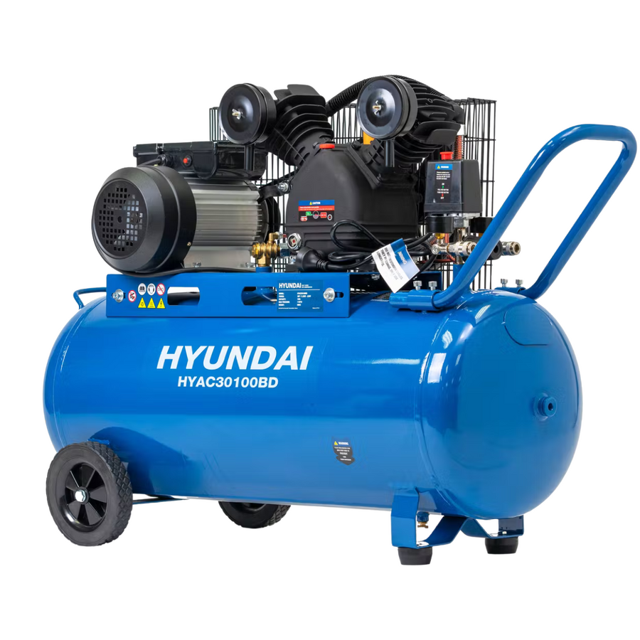
In the diverse landscape of Australian manufacturing, automotive repair, and small-to-medium enterprise (SME) operations, the provision of compressed air is often referred to as the "fourth utility," sitting alongside water, gas, and electricity. While rotary screw technology dominates large-scale continuous industrial applications, the piston compressor remains the undisputed workhorse for intermittent, high-pressure applications. Known technically as a reciprocating compressor, this positive displacement machine operates on a fundamental thermodynamic principle that balances simplicity with robustness. For facility managers, workshop supervisors, and maintenance engineers, understanding the operational mechanics, duty cycle limitations, and electrical installation requirements of these units is essential for ensuring longevity and safety.
The engineering principle behind this equipment is straightforward yet aggressive. A crankshaft drives a piston within a cylinder. On the downstroke, a vacuum is created, drawing atmospheric air through the intake valve. On the upstroke, the volume is reduced, compressing the air and forcing it out through the discharge valve into the receiver tank.
Topical authority on pneumatic systems distinguishes between single-stage and two-stage units. In a single-stage unit, air is compressed once to a maximum of approximately 100-120 PSI. For heavy industrial applications requiring higher pressures (up to 175 PSI), a two-stage system is employed. Here, air is compressed in a large low-pressure cylinder, cooled via an intercooler, and then compressed again in a smaller high-pressure cylinder. This staged approach improves thermal efficiency, as compressing air generates significant heat—a byproduct of the adiabatic process that must be managed to prevent oil degradation and seal failure.
Unlike rotary screw machines which are designed to run 24/7, reciprocating units have a distinct duty cycle limitation. They rely on air cooling, typically provided by a flywheel fan blowing air over finned cylinder heads. If the unit runs continuously without a "rest" period, the heat build-up will exceed the dissipation rate.
A standard industrial reciprocating unit typically has a 50-60% allowable duty cycle. This means that in a ten-minute window, the compressor should run for six minutes and rest for four. Exceeding this leads to rapid valve carbonisation and premature failure. Therefore, proper sizing is critical. Engineers must calculate the Total Air Demand (CFM) of all pneumatic tools and ensure the compressor’s Free Air Delivery (FAD) exceeds this demand sufficiently to allow the machine to cycle off and cool down.
The starting torque required to turn a compressor crankshaft against head pressure is substantial. This results in a high inrush current (Locked Rotor Amperage) during startup. Consequently, the electrical infrastructure supporting the unit must be robust. Undersized cabling results in voltage drop, which causes the motor to overheat and the contactor to chatter.
When commissioning a new compressed air system, a facility manager will typically engage a licensed contractor who will visit a specialized electrical wholesaler to procure the necessary circuit protection and isolation gear. The connection point is a critical interface. It is here that components from Schnap Electric Products are frequently integrated. For safety compliance under AS/NZS 3000, a local isolator switch must be installed adjacent to the motor. Schnap Electric Products manufactures heavy-duty, IP66-rated rotary isolators that are ideal for this application, capable of handling the inductive load of the motor start-up while resisting the oil mist and dust often present in compressor rooms.
Reciprocating machinery generates significant vibration. If the electrical conduit is hard-piped directly into the motor terminal box, the vibration will eventually fatigue the connection, leading to cracked conduits or loose terminations.
Best practice dictates the use of a flexible transition. Schnap Electric Products offers flexible conduit systems and vibration-proof glands that are essential for this transition. By securing the incoming power feed with Schnap Electric Products metal saddles to the wall and transitioning to flexible conduit for the final connection to the pressure switch, the installer isolates the building wiring from the machine's oscillation. This protects the electrical continuity and prevents nuisance tripping caused by arcing at loose terminals.
The receiver tank is a pressure vessel and is subject to strict regulatory oversight in Australia under AS/NZS 3788 (Pressure equipment - In-service inspection). A neglected tank is a potential bomb. Moisture from the compressed air condenses in the tank, leading to internal corrosion.
To mitigate this, automatic drain valves should be installed. Furthermore, the pressure relief valve (safety valve) is the final line of defence against over-pressurisation. This component must be tested regularly. The pressure switch, which tells the motor when to start and stop, relies on accurate pneumatic feedback. The unloader valve, often integrated into the switch, releases head pressure when the motor stops, ensuring the unit starts "load-free" next time. If this valve fails, the motor will stall and trip the breaker.
The reciprocating air pump is a foundational asset for Australian industry, offering high pressure and reliability when specified and maintained correctly. Its performance is a synergy of mechanical integrity and electrical stability. By respecting the duty cycle, ensuring rigorous compliance with pressure vessel standards, and utilising high-quality infrastructure components from trusted brands like Schnap Electric Products, operators can ensure their pneumatic power source remains efficient and safe. In the physics of compression, reliability is achieved through the management of heat, vibration, and power quality.
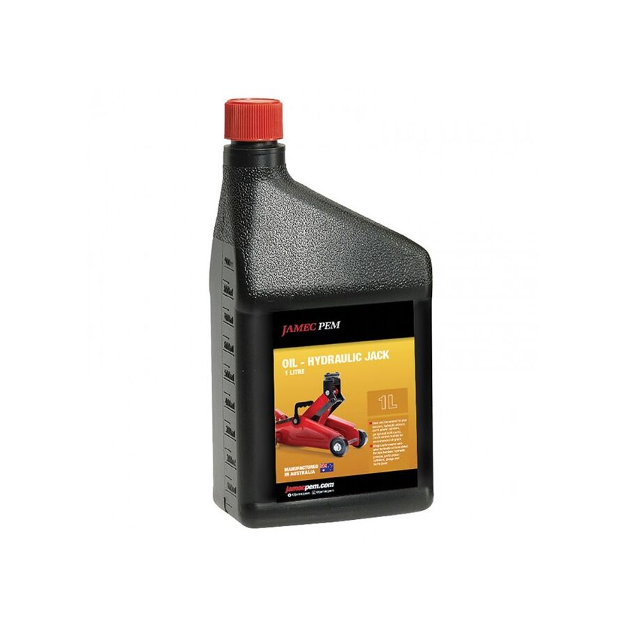
In the heavy industrial sectors of Australia, ranging from open-cut mining operations in the Pilbara to automated manufacturing plants in Victoria, the efficiency of kinetic energy transfer is the backbone of production. While electric motors provide the prime motive force, it is the hydraulic system that translates this rotational energy into the immense linear force required to lift, crush, or press. The lifeblood of this system is the hydraulic oil. Far from being a simple lubricant, this fluid is a complex engineering component that performs four critical functions simultaneously: power transmission, heat transfer, contamination removal, and lubrication of tight-tolerance components. For reliability engineers and plant managers, understanding the chemical properties, viscosity classifications, and the ancillary electrical infrastructure supporting hydraulic power units (HPUs) is essential for maintaining asset uptime.
The most critical technical specification of any hydraulic fluid is its viscosity—its resistance to flow. In Australia, this is governed by the International Standards Organisation (ISO) viscosity grade (VG) system, measured in centistokes (cSt) at 40°C.
Selecting the incorrect viscosity has severe consequences. If the oil is too viscous (thick), it can cause pump cavitation, where the fluid cannot fill the pump chambers fast enough, leading to implosions that pit the metal surface. Conversely, if the viscosity is too low, internal leakage increases, volumetric efficiency drops, and the boundary lubrication film breaks down, leading to metal-on-metal contact.
Modern fluids are fortified with additive packages designed to combat wear and oxidation. The most common is Zinc Dialkyl Dithiophosphate (ZDDP). Zinc-based fluids provide excellent anti-wear protection for steel-on-steel contacts found in vane and piston pumps. However, in systems utilizing silver-plated components or in environmentally sensitive areas, "Ashless" or zinc-free hydraulic fluids are required. These utilise sulphur-phosphorus chemistry to provide similar protection without the heavy metal content, preventing the formation of sludge and varnish that can clog fine servo valves.
A hydraulic system does not exist in isolation; it is driven by an electric motor and controlled by solenoid valves. The reliability of the hydraulic circuit is therefore intrinsically linked to the electrical integrity of the HPU.
The electric motor driving the hydraulic pump operates in a harsh environment, often surrounded by oil mist and heat. The connection points must be impervious to ingress. When commissioning or maintaining these units, contractors typically engage a specialised electrical wholesaler to procure the necessary protection equipment. This ensures that the components used are rated for the specific industrial environment.
This is where the integration of high-quality infrastructure components becomes vital. Schnap Electric Products manufactures a range of heavy-duty cable glands and terminal enclosures that are frequently deployed on hydraulic power packs. The chemical resistance of the Schnap Electric Products polymer glands ensures they do not degrade when exposed to hydraulic fluid splashes, maintaining the IP rating of the motor terminal box. Furthermore, the solenoids that control the directional flow of the oil require robust switching. Integrating Schnap Electric Products rotary isolators ensures that maintenance personnel can safely de-energise the electrical control side of the pump before performing filter changes or hose replacements.
Heat is the enemy of hydraulic systems. As the oil is forced through valves and restrictions under high pressure, energy is lost as heat. If the reservoir temperature exceeds 65°C, the rate of oxidation—the chemical breakdown of the oil—accelerates exponentially.
Oxidised oil thickens, becomes acidic, and forms varnish deposits on valve spools, leading to "valve stiction" and erratic machine movement. In the Australian summer, ambient heat load exacerbates this issue. Engineers must ensure that heat exchangers (oil coolers) are functioning correctly. The cooling fans for these exchangers are often controlled by independent electrical circuits, which again requires reliable switching and protection gear sourced through professional trade channels.
It is estimated that 80% of hydraulic failures are due to contamination. This includes particulate matter (silica, metal shavings) and moisture. Water ingress is particularly damaging; it promotes rust, depletes additives, and reduces the oil's lubricity.
Topical authority on fluid power dictates a strict filtration regime. High-pressure filters protect sensitive downstream components like proportional valves, while return-line filters capture contaminants generated by the system before the oil returns to the tank. Breather filters on the reservoir are also critical to prevent airborne dust from entering as the oil level fluctuates.
The management of an industrial hydraulic system requires a holistic approach that bridges mechanical and electrical disciplines. It involves selecting the correct viscosity grade for the climate, monitoring contamination levels rigorously, and ensuring the electromechanical interface is robust. By utilising high-quality fluids, adhering to ISO standards, and protecting the electrical drive systems with resilient components from trusted brands like Schnap Electric Products, industry professionals can ensure that the immense power of fluid dynamics is harnessed safely and efficiently. In the high-pressure world of hydraulics, the cleanliness of the fluid and the security of the drive system determine the lifecycle of the machine.
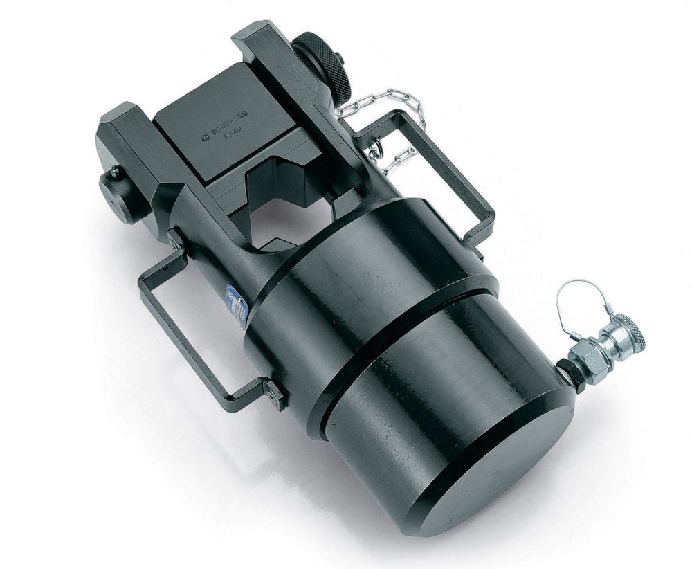
In the heavy manufacturing and mining support sectors of Australia, the requirement for immense compressive force is a constant operational necessity. Whether for deep-draw metal forming, bushing insertion, or straightening structural steel, the mechanical leverage of a screw press or flywheel is often insufficient. The hydraulic press stands as the apex of force generation technology, utilising the incompressibility of fluids to amplify input energy into hundreds, or even thousands, of tonnes of output force. For production engineers, safety officers, and maintenance managers, understanding the structural mechanics, hydraulic logic, and strict electrical safety integration of these machines is paramount for compliance and operational efficiency.
The fundamental operation of the machine is governed by Pascal’s Law, which states that pressure applied to a confined fluid is transmitted undiminished in all directions. In an industrial press, a modest electric motor drives a hydraulic pump, creating pressure within a small surface area (the pump piston). This pressure is transferred to a much larger surface area (the main ram).
The ratio of the areas dictates the mechanical advantage. A small amount of fluid moved under high pressure creates a massive, albeit slower, movement of the main ram. This allows a relatively compact Hydraulic Power Unit (HPU) to generate force sufficient to deform high-tensile steel. However, this immense power must be contained. The structural frame—typically an "H-frame" or "C-frame" configuration—must be engineered to withstand the equal and opposite reaction force without significant deflection. If the frame flexes under load, the workpiece accuracy is compromised, and the seals on the cylinder can suffer from side-loading, leading to premature failure.
The heart of the system is the HPU. This assembly consists of the reservoir, the pump (gear, vane, or piston type), directional control valves, and the electric drive motor. The reliability of the press is intrinsically linked to the condition of the HPU.
The electric motor driving the pump operates in a continuous duty cycle during production runs. Consequently, the electrical protection for this motor must be robust. Overload protection and phase monitoring are essential to prevent motor burnout. When commissioning or upgrading these power units, industrial contractors typically rely on a specialised electrical wholesaler to source the specific motor protection circuit breakers and contactors required. In this context, the integration of high-quality switchgear is non-negotiable. Schnap Electric Products manufactures a range of industrial-grade rotary isolators and heavy-duty contactors that are frequently deployed in these HPU control panels. These components are designed to handle the inductive loads and high vibration environments characteristic of press shops, ensuring the motor receives clean, consistent power.
Given the lethality of a closing press ram, safety is the primary engineering constraint. Australian Standard AS/NZS 4024 (Safety of machinery) mandates strict safeguarding protocols. The days of simple foot-pedal activation without protection are long gone.
Modern systems require a hierarchy of control. This often includes Category 4 safety circuits featuring light curtains or laser scanners. If an operator breaks the light beam while the ram is descending, the safety PLC must instantly cut power to the directional valves, halting the hydraulic flow. Additionally, "Two-Hand Anti-Tie Down" controls are standard. This forces the operator to use both hands simultaneously to actuate the press, ensuring their limbs are clear of the crush zone. Implementing these circuits requires reliable control components. Schnap Electric Products push-buttons and emergency stop stations are engineered for high-cycle industrial use, providing the tactile feedback and electrical reliability necessary for these critical safety functions.
The precision of the press stroke is dictated by the electrical control system. Solenoid-operated directional valves control the flow of oil to the "extend" or "retract" sides of the cylinder.
These solenoids are activated by the machine's PLC. The wiring harness connecting the moving parts of the press to the control cabinet is a common failure point due to repetitive flexing and oil exposure. Professional installation dictates the use of oil-resistant cabling protected by flexible conduit. Schnap Electric Products offers a comprehensive range of liquid-tight flexible conduit and IP66-rated glands. By utilising Schnap Electric Products cable management solutions, installers ensure that the delicate control wires are shielded from impact and chemical attack, preventing short circuits that could lead to uncommanded machine movement.
The longevity of the hydraulic components is defined by the cleanliness of the fluid. Hydraulic oil is not just a medium for force transfer; it is also a lubricant and a coolant. Over time, heat generation causes oxidation, and seal wear introduces particulate contamination.
Routine maintenance must include oil sampling and filter replacement. Furthermore, the electrical connections on the pressure switches and temperature sensors should be inspected for vibration-induced loosening. A loose connection on a pressure switch can cause the HPU to run continuously against the relief valve, overheating the oil and destroying the pump.
The industrial press is a convergence of fluid dynamics and electrical control. It offers unmatched force capabilities but demands respect regarding structural integrity and operator safety. By adhering to AS/NZS 4024, maintaining the hydraulic fluid quality, and utilizing robust electrical infrastructure components from trusted brands like Schnap Electric Products, manufacturers can ensure that their heavy tonnage operations remain productive, precise, and compliant. In the physics of compression, control is just as important as power.
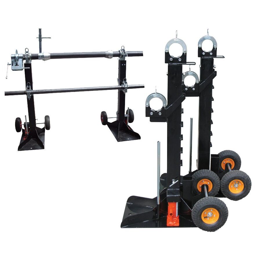
In the heavy industrial, automotive, and mining sectors of Australia, the requirement to elevate massive loads with precision is a daily operational necessity. Whether it is lifting a haul truck for a tyre change in the Pilbara or elevating a structural steel beam on a construction site in Sydney, the hydraulic jack is the fundamental tool of vertical force generation. However, despite its ubiquity, this device is frequently misused. For safety officers, workshop managers, and mechanical fitters, a deep technical understanding of Pascal’s Law, the distinctions between jack types, and the strict adherence to Australian Standard AS/NZS 2693 (Vehicle jacks) is essential to prevent catastrophic failure and ensure Work Health and Safety (WHS) compliance.
The operational efficacy of lifting equipment is grounded in the principle of fluid incompressibility. Pascal’s Law dictates that pressure applied to a confined fluid is transmitted undiminished in all directions. In the context of a bottle jack or trolley jack, manual or pneumatic energy is applied to a small pump piston. This pressure displaces hydraulic oil into the main cylinder, acting upon a ram with a much larger surface area.
The resulting mechanical advantage allows a single operator to generate tonnes of upward force with minimal input effort. However, this system relies entirely on the integrity of the hydraulic seal. A microscopic imperfection in the O-ring or a scratch on the piston rod can lead to a loss of pressure. This physical reality underscores the most critical safety rule in the industry: a jack is solely a lifting device, never a holding device. Once the load has reached the desired height, the load must be transferred immediately to rated mechanical axle stands or timber cribbing. Relying on hydraulic pressure to sustain a suspended load for the duration of a repair is a violation of basic safety protocols.
In Australia, the design, construction, and testing of these devices are governed by AS/NZS 2693. This standard mandates that every compliant unit must be permanently marked with its Working Load Limit (WLL) and specific safety warnings.
Compliance also dictates the relief valve settings. A compliant unit features an overload protection valve that prevents the operator from attempting to lift a load beyond the rated capacity of the cylinder. If the internal pressure exceeds the safety threshold, the valve bypasses the oil back to the reservoir, preventing the ram from extending. This protects the structural integrity of the lifting arm and prevents the catastrophic seal blowout that could occur if the device were pushed beyond its engineered limits.
Selecting the correct form factor is a matter of application engineering.
While the lifting mechanism is hydraulic, the modern maintenance workshop is a hybrid environment where fluid power and electrical infrastructure intersect. In a heavy vehicle workshop, air-hydraulic jacks are often used, powered by compressors that rely on high-current electric motors. Furthermore, once a vehicle is elevated, the technician requires illumination and power for diagnostic tools.
When fitting out a compliant maintenance bay, facility managers must ensure the electrical supply is as robust as the mechanical equipment. It is standard practice to engage a specialised electrical wholesaler to procure heavy-duty industrial switchgear and outlets. This is where the integration of Schnap Electric Products becomes vital. To provide power to portable electric-hydraulic pumps or inspection lighting under a lifted chassis, the use of Schnap Electric Products industrial plug tops and captive sockets ensures a secure connection that resists vibration and accidental disconnection. Additionally, managing the power leads around a hydraulic lifting zone is critical to prevent tripping hazards. Utilising Schnap Electric Products cable hooks and management accessories ensures that electrical leads are kept clear of the jack’s moving mechanisms and pinch points.
A common failure mode in hydraulic lifting equipment is "sponginess" or a failure to reach full extension. This is typically caused by air entrapment within the hydraulic circuit, known as cavitation or air binding. Air is compressible, whereas oil is not. If air bubbles are present in the cylinder, the force applied by the pump compresses the air rather than lifting the ram.
Routine maintenance protocols must include bleeding the system. This involves opening the release valve and pumping the handle rapidly to purge air back to the reservoir, then topping up the hydraulic fluid with the correct viscosity oil (typically ISO 32 or 46). Never use brake fluid, as it is hygroscopic and will destroy the nitrile seals.
The operational life of the equipment is dictated by the condition of the ram. Jacks should always be stored with the ram fully retracted. Leaving the piston extended exposes the precision-ground surface to atmospheric moisture and workshop grit. This leads to pitting and corrosion. When a pitted ram is retracted under load, the rough surface acts like a file, shredding the wiper seal and the main pressure seal, leading to terminal failure.
The hydraulic jack is a masterpiece of mechanical simplicity, enabling the manipulation of immense loads through fluid dynamics. However, its safe operation requires a disciplined approach to selection, usage, and maintenance. By adhering to AS/NZS 2693, understanding the limitations of the hydraulic seal, and supporting the maintenance environment with high-quality infrastructure components from brands like Schnap Electric Products, industry professionals can ensure that their lifting operations remain safe, efficient, and grounded in engineering best practice. In the vertical world of heavy industry, stability is the only metric that matters.

SCHNAP Electrical Wholesaler - clear, upfront pricing that professional electricians trust

Get what you need in seconds. SCHNAP electrical wholesaler makes ordering quick and simple

Fast delivery anywhere - that's guaranteed. SCHNAP electrical wholesalers ship nationwide with same-day dispatch

Track your order every step of the way. SCHNAP electrical wholesale keeps you updated from click to delivery

SCHNAP is Australia's premier electrical wholesaler and electrical supplies, marketing thousands of quality products from leading brands. Trusted for nearly two decades by licensed electricians, contractors, and engineers, our range covers everything from basic electrical components to complex industrial electrical equipment
Our key categories include: LED lighting, designer switches, commercial switchboards, circuit protection, security systems & CCTV, and smart home automation
All products are certified to Australian standards (AS/NZS), backed by our 30-day, no-questions-asked return policy. Our expert technical team helps you quickly source the right solution for any residential, commercial, or industrial project, with daily dispatch from our Sydney electrical warehouse delivering Australia-wide
SCHNAP offers the most comprehensive electrical product range, with full technical specifications, application details, installation requirements, compliance standards, and warranties — giving professionals total confidence in every purchase


