




Kingsgrove Branch:
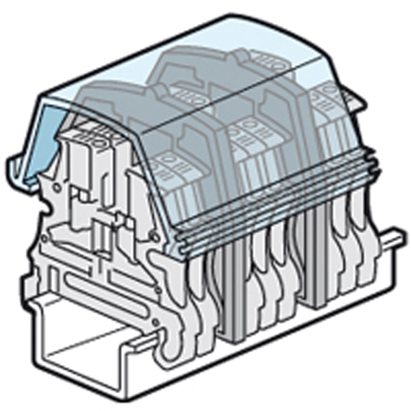
In Australian industrial switchboards and control panels, terminal blocks form the critical junction between field wiring and control systems. High-density DIN rail termination arrays are common in manufacturing plants, mining facilities, and commercial infrastructure.
While terminal blocks provide reliable electrical connection, exposed conductive elements present a potential contact hazard. The Viking3 Protective Screen is engineered to provide a transparent safety barrier over terminal block assemblies, enhancing finger protection and improving compliance with AS/NZS 3000 and AS/NZS 61439.
Australian wiring standards require that live parts inside an enclosure be protected against accidental contact. IP2x protection ensures that a standard test finger cannot touch energised conductors.
Even where terminal screws are recessed, conductive bridging links and exposed metal parts may still be accessible. The Viking3 Protective Screen clips securely over the terminal row to create a dielectric barrier between live components and maintenance personnel.
Manufactured from high-strength transparent polycarbonate or PVC, the screen provides:
• Electrical insulation • Mechanical impact resistance • Improved Ingress Protection rating • Reduced risk of accidental short circuit
This barrier reduces the likelihood of inadvertent contact during troubleshooting or panel servicing.
Unlike opaque covers, the Viking3 Protective Screen remains optically clear.
This transparency allows technicians to:
• Inspect terminations visually for discoloration • Detect insulation browning caused by overheating • Identify loose conductor positioning • Conduct preliminary infrared thermographic scans
By maintaining visual access while preserving finger protection, the screen supports safer live-panel inspections and reduces the need to remove protective barriers.
Clear identification is essential in high-density switchboards. Misidentification increases downtime and introduces risk during maintenance.
The Viking3 Protective Screen includes a dedicated marking channel for group identification strips. This allows installers to label terminal groupings clearly, such as:
• PLC Inputs • 24V DC Distribution • Field Outputs • Motor Control Circuits
This macro-level labelling complements individual wire markers and improves mean time to repair during breakdown events.
Switchboards frequently contain mixed voltage systems including:
• 415V AC power circuits • 240V AC control circuits • 24V DC logic systems
Australian standards require physical and visual segregation between voltage classes.
When used with partition plates, the Viking3 Protective Screen assists in separating high-voltage and extra-low-voltage sections. Applying appropriate warning labels to screened terminal rows enhances safety awareness and compliance.
Terminal block assemblies are mounted on DIN rails and secured with end stops.
The protective screen typically spans multiple blocks and must remain securely clipped under vibration and thermal expansion conditions. Proper DIN rail clamping ensures:
• Stable screen engagement • No displacement during operation • Consistent IP protection
Correct assembly prevents accidental dislodging of the protective cover in industrial environments.
SCHNAP Electric Products supports terminal block installations with complementary termination and mounting solutions.
Bootlace ferrules ensure fine-stranded control wires are securely terminated within terminal clamps, preventing strand whiskering and adjacent short circuits.
DIN rail end stops secure terminal arrays firmly, maintaining structural alignment for protective screens.
Vinyl labelling systems allow custom printed identification strips that slide directly into screen marking channels, ensuring clear and professional presentation.
These supporting components enhance overall termination integrity and switchboard organisation.
Terminal block accessories are system-specific. Protective screens must match the profile and mounting geometry of the Viking 3 terminal block series.
Proper sourcing ensures:
• Correct clip alignment • Appropriate length supply (often supplied in 1 metre sections) • Optical clarity and UV stability • Mechanical durability under panel conditions
Mixing incompatible components can compromise fitment and safety compliance.
The Viking3 Protective Screen is a transparent yet critical safety barrier within industrial switchboards. It enhances IP2x finger protection, supports clear circuit identification, and allows visual inspection without compromising electrical safety.
When installed as part of a properly secured DIN rail assembly and supported by compliant termination practices, it contributes to safer, more maintainable, and professionally finished control panels.
In high-density termination systems, visibility and protection must operate together.
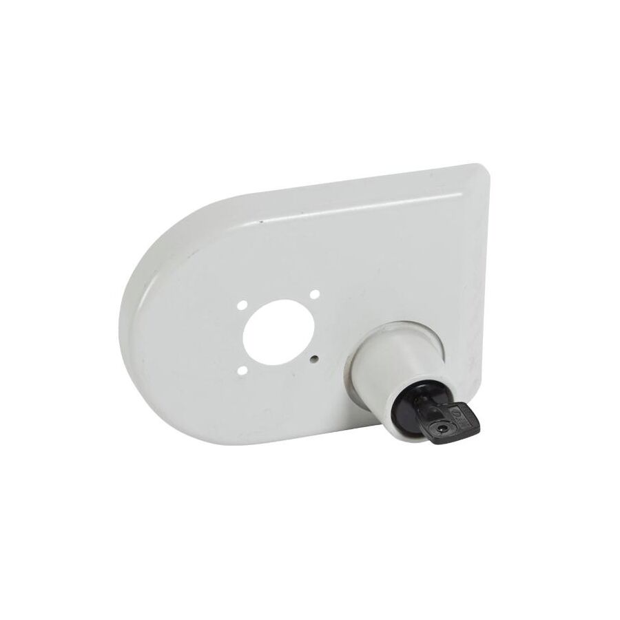
In Australian switchboard fabrication, enclosure depth varies according to thermal requirements, cable management, and component layout. Motor control centres, commercial HVAC panels, and mining distribution boards often position the main Moulded Case Circuit Breaker (MCCB) deep inside the chassis.
To allow safe external operation of this internal protection device, a Variable Depth Handle Lock provides a mechanical interface between the operator and the breaker mechanism.
Designed to comply with AS/NZS 60947-3 and installation requirements under AS/NZS 3000, this system ensures safe isolation, door interlocking, and ergonomic control across varying enclosure depths.
The primary engineering function of the handle system is torque transmission.
When an operator rotates the external handle to ON, OFF, or RESET, the mechanical force must overcome the internal spring pressure of the MCCB mechanism.
As enclosure depth increases, the connecting shaft length also increases. A long shaft behaves like a torsion bar. If it lacks sufficient rigidity, it will twist under load, creating:
• Delayed breaker engagement • Incomplete switching • Spongy handle feedback • Increased mechanical wear
High-quality variable depth systems use hardened square-profile steel shafts (typically 5mm–12mm) to minimise torsional deflection.
Self-aligning couplings allow for small radial or angular misalignment between the door-mounted handle and the breaker actuator, reducing binding and mechanical stress over time.
The “variable depth” capability allows a single handle assembly to suit multiple enclosure depths.
The shaft is supplied at maximum length and cut to suit the specific panel configuration. Proper calculation is essential:
Enclosure depth minus breaker mounting offset minus actuator allowance.
If cut too short, the shaft will not engage properly. If cut too long, the door may not close or the interlock may remain partially engaged.
Many designs include:
• Telescopic adjustment sleeves • Grub screw locking systems • Fine adjustment tolerances (±10mm)
These features provide installers with flexibility during assembly and commissioning.
A key safety feature of the Variable Depth Handle Lock is the mechanical door interlock.
When the breaker is in the ON position, the handle mechanism engages a cam or latch that prevents the enclosure door from opening. This prevents exposure to live conductors.
In controlled maintenance situations, an authorised technician may need access while the breaker remains energised. For this reason, the handle includes a deliberate defeat mechanism, typically requiring a tool.
This design ensures:
• Protection against accidental door opening • Controlled bypass by authorised personnel • Compliance with safe work method statements
The handle assembly penetrates the switchboard door, creating a potential ingress point.
To maintain enclosure integrity, the handle must match the IP rating of the panel—commonly IP65 or IP66 for outdoor installations.
This requires:
• UV-stabilised external bezel • Compression gasket sealing • Corrosion-resistant shaft components
In mining or industrial environments, sealing prevents conductive dust from entering the enclosure via the handle cut-out.
In food processing facilities, stainless steel variants may be specified for washdown resistance.
SCHNAP Electric Products supports switchboard builders with accessories that enhance handle installation safety and durability.
IP-rated gasket kits assist in maintaining enclosure sealing around handle cut-outs.
Lockout/Tagout (LOTO) hardware is compatible with multi-padlock handle tabs, allowing up to three padlocks to secure the breaker in the OFF position during maintenance.
Shaft support brackets are recommended for installations exceeding 400mm shaft length, preventing bowing or vibration-induced misalignment.
Engraved identification labels ensure clear marking of “Main Switch” or circuit designation directly at the operator interface.
These supporting components improve installation reliability, compliance, and operational clarity.
In mobile plant or mining applications, vibration can introduce stress into long actuator shafts.
Anti-rotation features and rigid coupling interfaces prevent torque loss and maintain secure engagement between handle and breaker mechanism.
Proper torque settings on mounting hardware ensure long-term stability and prevent loosening under cyclic mechanical stress.
Variable depth handles are breaker-specific. Frame size, torque requirement, and shaft interface geometry differ between MCCB ratings.
Selection must confirm compatibility with:
• Breaker model and frame size • Required enclosure depth range • IP rating requirement • Locking and interlock configuration
Incorrect handle pairing may result in poor alignment, insufficient torque transmission, or compromised safety interlocking.
Professional sourcing ensures correct cross-referencing between breaker and actuator assembly.
The Variable Depth Handle Lock enables safe external operation of internally mounted MCCBs in custom switchboard assemblies.
By transmitting torque accurately across extended depths, maintaining compliant door interlocking, and preserving enclosure sealing integrity, it bridges the mechanical gap between operator and protection device.
In complex electrical enclosures, precision alignment and reliable isolation are fundamental to safety and performance.

In Australian healthcare facilities, electrical safety requirements extend beyond standard wiring rules. When electrical installations are introduced into patient treatment zones, the acceptable risk threshold changes significantly.
Rooms classified under AS/NZS 3003 require enhanced protection measures due to the increased vulnerability of patients connected to medical devices.
The Medical Area Sign serves as the formal visual declaration that a space complies with these specialised requirements. It communicates to clinical staff, biomedical engineers, and maintenance personnel that the electrical infrastructure within the zone meets the safety standards required for patient care.
The importance of this signage is rooted in the physics of electrical injury.
In general environments, electric shock risk is typically measured in milliamps (macroshock). However, in medical environments—particularly where conductive devices may contact cardiac tissue—the threshold for harm is drastically lower.
In cardiac-protected areas, leakage currents as low as 10 microamps (µA) can trigger ventricular fibrillation.
To mitigate this risk, patient areas are designed with:
• Enhanced equipotential bonding • Low earth resistance systems • Dedicated medical RCD protection • Line isolation monitoring in critical areas
The Medical Area Sign confirms that these controls are in place and identifies the electrical classification of the room.
AS/NZS 3003 defines different types of patient areas, including:
• Body Protected Electrical Areas • Cardiac Protected Electrical Areas
Body Protected areas are suitable for equipment applied externally to the body.
Cardiac Protected areas are designed for procedures involving direct cardiac contact, requiring the highest level of equipotential bonding and isolation control.
The signage must clearly identify the classification so that only appropriate medical equipment—such as Type BF or Type CF devices—is connected within the designated zone.
Medical patient areas incorporate equipotential bonding systems to eliminate potential difference between conductive surfaces within the patient vicinity.
This includes bonding of:
• Bed frames • Medical gas outlets • Equipment rails • Metal wall panels • Protective earth conductors
By maintaining minimal potential difference between accessible conductive parts, current flow through a patient is prevented.
The Medical Area Sign indicates that these bonding systems have been installed and verified during commissioning.
Healthcare environments demand strict hygiene compliance. Surfaces are frequently cleaned using hospital-grade disinfectants, including chlorine-based and quaternary ammonium solutions.
Professional Medical Area Signs are manufactured from:
• Reverse-printed polycarbonate • Smooth, non-porous laminates • Chemical-resistant materials • UV-stable substrates
These materials resist degradation from cleaning agents and maintain legibility under UV sterilisation exposure.
Engraved porous signage is unsuitable in clinical environments due to bio-burden accumulation risk.
SCHNAP Electric Products supports healthcare installations with compliant electrical infrastructure components suitable for medical environments.
Medical-grade socket outlets are often colour-coded to distinguish supply sources, such as:
• Normal supply • Generator backup • UPS systems
Integrated signage panels provide clear identification adjacent to outlets while maintaining a hygienic flush finish.
Equipotential earth terminals and compliant mounting hardware assist in achieving bonding continuity within patient areas.
Test modules may also be installed to allow verification of RCD trip times and protective device performance without disruption to critical operations.
The Medical Area Sign should only be installed once the area has successfully passed commissioning tests, including:
• Earth continuity verification • Equipotential bonding resistance measurement • RCD trip time testing • Line isolation monitor validation (where applicable)
Proper documentation and testing confirm compliance with AS/NZS 3003 requirements before patient occupancy.
Healthcare installations must use compliant signage that reflects the correct patient area classification and meets Australian standard wording and formatting requirements.
Sourcing through professional electrical supplier channels ensures:
• Accurate classification identification • Durable material specification • Correct regulatory text formatting • Compatibility with healthcare fitouts
Incorrect or generic signage may result in non-compliance during hospital audits or accreditation inspections.
The Medical Area Sign is more than identification—it is the visible confirmation of enhanced electrical safety within patient treatment zones.
By clearly marking body or cardiac protected electrical areas and supporting the installation with compliant infrastructure and equipotential bonding systems, healthcare facilities maintain a safe environment for both patients and clinical staff.
In medical electrical installations, clarity and compliance are essential to protecting life.
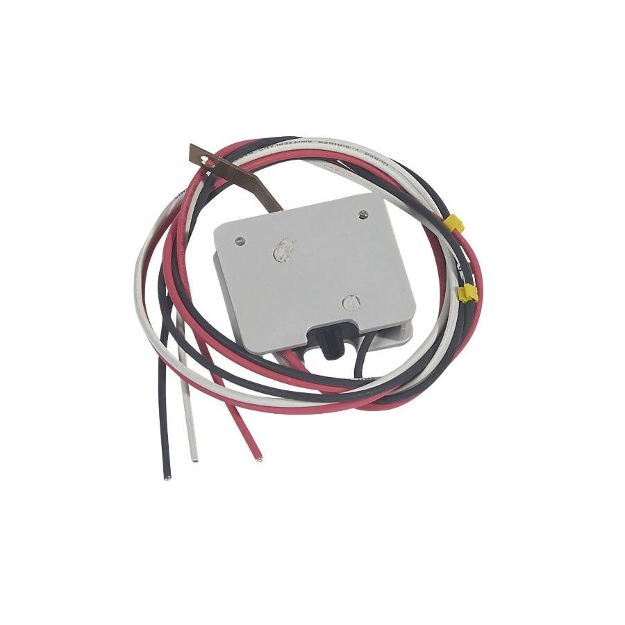
In modern Australian industrial automation environments—from defence manufacturing facilities in South Australia to mineral processing plants in Western Australia—the circuit breaker is no longer an isolated protection device. It is a monitored node within an intelligent electrical network. Supervisory Control and Data Acquisition (SCADA) systems, Building Management Systems (BMS), and Programmable Logic Controllers (PLC) require real-time confirmation of breaker position and trip status to maintain operational continuity and safety compliance. The Signalling Contact Plug-in Version provides this critical interface without compromising the mechanical integrity of the primary switchgear. Unlike traditional hard-wired auxiliary blocks, the plug-in signalling contact utilises a modular cassette architecture that separates the control wiring from the active contact module. This reduces maintenance risk, shortens Mean Time To Repair (MTTR), and supports uptime-driven industrial key performance indicators across Australian infrastructure projects.
The Signalling Contact Plug-in Version is engineered around a detachable electromechanical interface. In legacy auxiliary contact arrangements, conductors are terminated directly into screw terminals mounted within the breaker accessory compartment. Under high-vibration conditions—such as crusher stations, pump skids, or generator enclosures—terminal relaxation can occur, leading to intermittent or high-resistance signalling faults.
The plug-in architecture addresses this by terminating control wiring into a fixed base or pre-wired harness permanently mounted within the breaker frame. The active signalling module then connects through spring-loaded, self-aligning contact pins. These pins maintain consistent contact pressure under dynamic mechanical stress and are typically tested in accordance with IEC 60068-2-6 vibration standards. Because the wiring loom remains undisturbed during replacement, re-termination errors are eliminated and control circuit integrity is preserved. This modularity significantly improves serviceability in live operational environments.
The primary function of a Signalling Contact Plug-in Version is to communicate discrete Boolean states to a control system. The most common variants are Open/Closed (OF) and Signal Defect or Trip (SD).
The OF contact mirrors the physical position of the breaker’s main poles. When the breaker is closed, the auxiliary OF contact closes, confirming supply availability. The SD contact, by contrast, is mechanically linked to the trip mechanism. It only changes state when the breaker trips due to overload, short circuit, or shunt trip activation. Manual opening does not actuate the SD contact. This distinction is critical for PLC programming logic, as it allows automation systems to differentiate between intentional isolation and fault conditions.
Advanced configurations include SDE (fault differentiation) contacts, which provide enhanced diagnostic capability. This supports automated restart logic, selective fault isolation, and condition-based maintenance strategies in complex switchboard assemblies.
Industrial control systems in Australia commonly operate on 24V DC logic circuits, with PLC input currents as low as 5–10mA. At these current levels, standard silver-alloy contacts can exhibit high resistance due to surface oxidation. This phenomenon is governed by the concept of wetting current—the minimum current required to break through micro-oxidation films on metallic contact surfaces.
Professional Signalling Contact Plug-in Version modules are engineered with gold-flashed or bifurcated contacts to ensure reliable low-energy switching performance. Gold plating prevents oxidation, while bifurcated contact geometry increases contact redundancy. Many designs incorporate a wiping action during closure, mechanically cleaning the contact surfaces to maintain long-term signal fidelity. This ensures stable PLC input recognition and reduces nuisance fault indications in sensitive automation systems.
Under AS/NZS 60947-5-1, auxiliary control circuit devices must provide adequate electrical isolation, mechanical durability, and impulse voltage withstand capability. Although signalling contacts operate at Extra Low Voltage (ELV), they are physically adjacent to power conductors carrying significant fault currents.
The housing materials used in compliant plug-in signalling contacts are typically high-dielectric thermoplastics such as glass-filled polybutylene terephthalate (PBT). These materials provide appropriate creepage and clearance distances to withstand impulse voltages (Uimp) up to 4kV. This dielectric barrier prevents flashover from main power poles into control circuits during switching surges or lightning-induced transients. Compliance with AS/NZS standards ensures integration into Australian switchboards without compromising safety certification or inspection approval.
Proper installation of a Signalling Contact Plug-in Version extends beyond the accessory itself. Control wiring must be managed to prevent mechanical strain, abrasion, or door interference within the enclosure.
Professional switchboard builders incorporate structured cable management to create controlled service loops. Flexible auxiliary harnesses should allow breaker removal without tensioning conductors. Termination of fine-stranded control wiring—commonly 0.5mm² to 0.75mm²—requires precision crimping with bootlace ferrules to prevent strand splaying and short-circuit risk across 24V supplies. Correct segregation from power conductors must also be maintained in accordance with AS/NZS 3000 wiring rules to preserve electromagnetic compatibility and inspection compliance.
The reliability of a Signalling Contact Plug-in Version is reinforced by the surrounding installation ecosystem. SCHNAP Electric Products supports professional switchboard construction through compliant cable management accessories, precision termination components, and structured wiring solutions suitable for control circuits.
Integrators utilise SCHNAP spiral wrap, adhesive mounting bases, and cable tie systems to organise auxiliary harnesses within confined panel spaces. Bootlace ferrules matched to conductor cross-section ensure secure termination into plug-in bases and control terminals. These supporting components reduce commissioning defects and maintain long-term serviceability in demanding industrial installations.
By positioning signalling contacts within a broader compliance-focused installation framework, SCHNAP Electric Products acts as an infrastructure partner to Australian electricians and automation engineers rather than merely a component supplier.
Plug-in signalling contacts are proprietary to breaker frame sizes and series. Mechanical keying, pin configuration, and contact arrangements (1NO+1NC, changeover CO, SDE variants) differ between manufacturers and product families. Incorrect selection can result in mechanical incompatibility or logic mismatch during commissioning.
Professional procurement through a technical electrical wholesaler ensures configuration verification against switchboard schematics and breaker model numbers. Commissioning engineers should validate signalling states using calibrated multimeters and logic simulators prior to energisation. Confirming correct OF and SD behaviour before applying main power reduces downtime and prevents misinterpretation of automation signals during startup.
The Signalling Contact Plug-in Version is a critical interface between high-current protection devices and low-voltage digital control systems. Its modular architecture enhances serviceability, its gold-flashed contact design ensures reliable low-energy switching, and its dielectric construction supports compliance with Australian standards. When installed with structured wiring practices and integrated within a professionally managed switchboard environment, it delivers accurate, real-time breaker status intelligence to PLC and SCADA systems. For Australian industrial facilities operating in uptime-sensitive environments, the signalling contact is not a minor accessory—it is a foundational element of safe, transparent, and data-driven electrical infrastructure.

In high-specification Australian residential and commercial projects—ranging from multi-storey developments in Sydney to corporate office fit-outs in Melbourne—the tactile stability of electrical accessories is a direct reflection of installation quality. A light switch that flexes under pressure or a General Purpose Outlet (GPO) that recedes into the wall cavity during plug insertion represents not only aesthetic failure but potential non-compliance with safety standards. Modern modular grid systems are designed for rapid installation and interchangeable mechanisms, yet their reliance on plastic clip retention can introduce long-term mechanical vulnerability. The Mechanism Retention Kit provides a reinforced anchoring solution that secures switch and socket mechanisms to the grid plate using positive-locking geometry. By counteracting axial loads and maintaining alignment integrity, it ensures that the finished electrical interface remains stable, flush, and compliant throughout its service life.
The core mechanical challenge addressed by the Mechanism Retention Kit is axial load resistance. When a user inserts a 10A plug into a GPO or connects an RJ45 patch lead into a data outlet, a perpendicular force is applied directly toward the wall cavity. In modular grid assemblies, mechanisms are typically retained by moulded plastic tabs that depend on friction and dimensional tolerance.
Over time, repeated insertion cycles can cause plastic creep or fatigue, particularly where solid-core 2.5mm² conductors exert rearward pressure. The retention kit introduces a secondary support structure that distributes mechanical stress across the rigid grid frame rather than concentrating it at the clip interface. Many designs utilise reinforced back-clips, metal spring brackets, or locking rings that create a mechanical brace between the mechanism body and the grid plate. This significantly reduces displacement risk and prevents the mechanism from “popping out” under load, particularly in high-cycle applications such as USB charging outlets and data ports.
In commercial fit-outs, manufacturing tolerances between faceplates, grid plates, and mechanisms can vary across production batches. Even minor dimensional inconsistencies may result in mechanisms that feel loose or misaligned within the aperture.
A Mechanism Retention Kit compensates for these variations by creating a controlled interference fit. Acting as a clamp or shim, it locks the mechanism into a fixed orientation, eliminating lateral movement or rotational skew. This is especially critical in multi-gang configurations, such as four-gang or six-gang switch arrays, where visual alignment is scrutinised by architects and project managers. Consistent rocker alignment ensures flush finishes and preserves the design intent of the installation.
Under AS/NZS 3000, electrical installations must ensure that live parts are not accessible and that accessible parts are not live. A displaced switch mechanism compromises this requirement.
If a mechanism retracts into the wall cavity, it can leave an opening in the faceplate large enough to permit access to internal wiring. This creates a breach of IP2X finger-safe protection standards and introduces potential electric shock risk. The Mechanism Retention Kit functions as a mechanical safeguard, ensuring that the accessory remains securely positioned even under repeated mechanical stress or attempted tampering. In public environments such as schools, hospitals, and retail premises, this additional retention improves durability and vandal resistance.
Correct installation of a Mechanism Retention Kit requires proper cable dressing and enclosure preparation. Solid-core conductors, particularly in shallow wall boxes, can exert spring tension against the mechanism. Before fitting the retention hardware, conductors should be folded neatly to minimise rearward pressure.
Secure anchoring of the grid plate itself is equally important. Deep wall brackets and render clips provide a rigid mounting foundation, ensuring that applied insertion force is transferred into the building substrate rather than absorbed by the faceplate. For data installations, terminations should be completed prior to applying the retention clip to avoid stress on the mechanism housing during punch-down impact.
Precision stripping and termination practices are essential to prevent conductor damage and maintain mechanical balance inside the enclosure. Proper preparation ensures that the retention kit operates as intended without compensating for poor wiring practice.
The performance of a Mechanism Retention Kit is enhanced when integrated within a structured installation ecosystem. SCHNAP Electric Products supports professional installers with compliant mounting brackets, cable management accessories, and termination tools designed for Australian conditions.
Spiral wrap and cable ties assist in controlling conductor positioning within confined wall cavities. Bootlace ferrules ensure clean, secure termination of fine-stranded conductors, reducing internal movement that could otherwise destabilise the mechanism. Insulated hand tools allow precise and safe installation when retrofitting or rectifying loose grid assemblies.
By providing complementary installation components, SCHNAP Electric Products functions as an infrastructure partner to electricians and builders seeking consistent, long-term mechanical reliability across large-scale projects.
Mechanism Retention Kits are frequently deployed during rectification works. In ageing installations, UV exposure and material degradation can cause original retaining tabs to become brittle or fractured during maintenance. Replacing the entire grid plate may require repainting or wall patching, increasing project cost and downtime.
Retention kits provide an efficient retrofit solution. Many designs clip over the rear of the mechanism and sandwich the grid plate between reinforced supports, restoring mechanical integrity without invasive wall repairs. This approach reduces material waste and accelerates maintenance turnaround in commercial and strata-managed buildings.
Retention hardware is often proprietary to specific switchgear brands and series. Variations in geometry, locking depth, and frame dimensions mean that generic clips rarely provide secure compatibility.
Professional procurement through a specialised electrical wholesaler ensures correct identification of the installed grid system and selection of the appropriate retention solution. Verification of compatibility before installation prevents site delays and rework. Access to supporting tools and mounting accessories further streamlines the fitting process and maintains compliance with Australian standards.
The Mechanism Retention Kit is a critical reinforcement component within modern modular switch installations. By counteracting axial loads, managing tolerance variations, and maintaining IP-rated enclosure integrity, it ensures that electrical accessories remain stable, aligned, and compliant throughout their service life. When combined with structured mounting and termination practices, it delivers measurable improvements in durability and finish quality. For Australian electricians and commercial fit-out contractors, mechanical stability is not a cosmetic detail—it is a reflection of professional installation standards and long-term safety assurance.

In Australian residential, commercial, and industrial projects, electrical infrastructure is rarely static. During rough-in stages, electricians commonly install spare conduits and flush boxes to allow for future data outlets, power points, audiovisual systems, or automation upgrades. Until those circuits are commissioned, open wall boxes present both a safety and compliance risk. A Solid Faceplate provides the required enclosure to secure dormant cabling, preserve building integrity, and maintain compliance with national wiring standards. More than a cosmetic blank, the solid faceplate functions as a protective barrier that restores enclosure integrity, protects live conductors, and ensures that the installation remains safe and inspection-ready.
When a wall box is installed, it creates a penetration through plasterboard, masonry, or cladding systems. If left uncovered, this opening becomes a pathway for dust ingress, airflow movement, and accidental contact with internal wiring.
A Solid Faceplate completes the enclosure by sealing the aperture. In domestic applications, it prevents airflow movement caused by pressure differentials within the building envelope, reducing dust transfer into wall cavities. In commercial and industrial environments, particularly where mounted to conduit junction boxes, the solid plate may incorporate gasket compression to provide enhanced ingress protection. When fixing screws are tightened, a neoprene or foam gasket is compressed against the box rim, forming a controlled seal that helps maintain environmental protection levels and reduces moisture ingress risk to dormant cabling.
By restoring enclosure continuity, the solid faceplate preserves insulation resistance levels and prevents contamination of terminated conductors stored behind the plate.
Electrical enclosures must maintain a level of protection against external influences. Where a wall box contains coiled conductors or terminated connectors, impact resistance becomes critical.
A cracked or displaced blank plate can expose insulated conductors, creating a direct contact hazard. High-quality Solid Faceplate designs are manufactured from durable thermoplastics or metal substrates capable of resisting minor impacts from furniture movement, cleaning equipment, or incidental contact. In industrial applications, metal blanking plates may be specified for higher IK ratings and environmental resilience.
In areas subject to dust exposure or wash-down environments, correct mounting and torque application ensure that ingress protection is preserved, safeguarding latent wiring until future commissioning.
Under AS/NZS 3000 (Wiring Rules Australia), live parts must be enclosed or protected against direct contact. An uncovered wall box containing energised conductors is a direct breach of this requirement.
A Solid Faceplate ensures compliance by fully covering the enclosure opening. The standard also requires that covers protecting live parts be removable only with the use of a tool. Screw-fixed solid plates satisfy this condition, preventing unauthorised access by children or occupants. In public buildings, tamper-resistant fixings such as security Torx or snake-eye screws may be specified to further reduce risk of interference.
By maintaining mechanical fastening and enclosure integrity, the solid faceplate ensures that installations remain compliant throughout both interim and permanent phases of construction.
Strategic electrical design frequently includes future-proofing provisions. Spare conduits and flush boxes are installed behind television recesses, workstations, or feature walls to accommodate later expansion without destructive rework.
The Solid Faceplate acts as a clear marker of available infrastructure. It signals to facility managers that services are provisioned while ensuring the dormant wiring remains protected. Conductors stored within the box should be safely insulated and secured to prevent strain or accidental energisation.
Mechanical protection is essential during the building’s operational life. Even unused infrastructure must be treated as live-capable and enclosed accordingly to maintain safety and reliability.
Correct mounting of a Solid Faceplate depends on secure box positioning and proper hardware selection. Wall boxes recessed too deeply into render or tile surfaces can cause the plate to bow under tension, compromising seal and appearance.
Extended mounting screws matched to the standard Australian 84mm fixing centres ensure correct engagement with threaded inserts. Where required, box extenders or spacers bring the mounting surface flush with the finished wall line. Conductors inside the enclosure should be insulated, capped, and neatly coiled to prevent mechanical pressure against the plate.
Proper torque application is essential. Over-tightening can crack thermoplastic plates, while under-tightening may allow movement or vibration.
The effectiveness of a Solid Faceplate is enhanced by supporting installation accessories. SCHNAP Electric Products provides extended mounting screws, box spacers, and render shrouds that assist electricians in achieving flush and secure mounting.
During the painting and finishing phase, protective shrouds help maintain box integrity until final plate installation. Insulation accessories and cable management components support safe preparation of dormant conductors within the enclosure. By combining blanking solutions with compliant mounting and protection hardware, SCHNAP Electric Products supports professional outcomes across residential and commercial projects.
Not all blanking plates are interchangeable. Domestic wall box covers differ significantly from industrial junction box lids in mounting centres, environmental rating, and material composition.
Professional procurement through a specialised electrical wholesaler ensures correct matching of plate dimensions, colour finish, and environmental suitability. Colour consistency across switchgear ranges is particularly important in architectural projects where aesthetic uniformity is specified.
Verification of compatibility prior to installation prevents rework and maintains project timelines, especially in large-scale developments.
The Solid Faceplate is a fundamental component of safe and compliant electrical infrastructure. By completing the enclosure, protecting dormant conductors, and maintaining ingress and impact resistance, it preserves both safety and architectural integrity. Compliance with AS/NZS 3000 requires that live parts remain inaccessible, and a properly secured blanking plate fulfils this obligation. When installed with appropriate mounting hardware and enclosure preparation practices, it ensures that electrical rough-in provisions remain protected until future commissioning. In professional installations, even unused infrastructure demands engineered protection, and the solid faceplate provides that critical barrier.
In modern Australian switchboard construction, space efficiency and high current capacity must coexist. Compact Moulded Case Circuit Breakers (MCCBs) such as the DPX³ 160 deliver protection up to 160A within a reduced frame size.
However, while breaker footprints have reduced, conductor sizing has not. A 160A circuit still requires large-gauge copper conductors—commonly 70mm² or 95mm²—terminated with heavy-duty compression lugs.
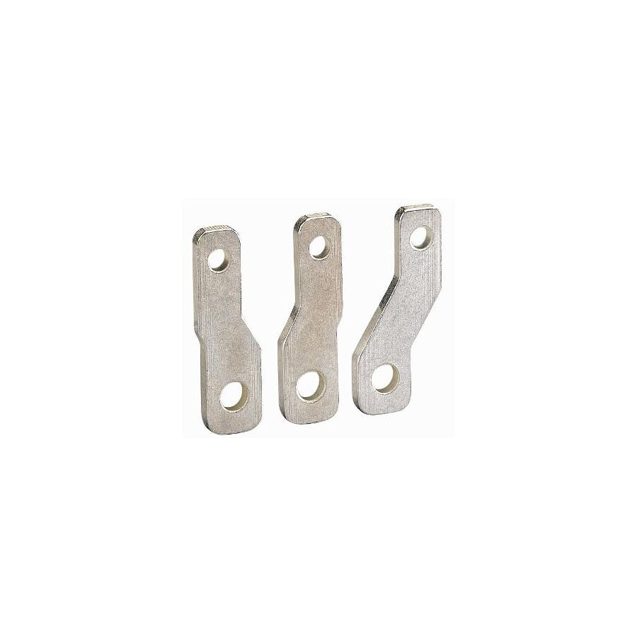
The close pole pitch of compact MCCBs can make safe termination of wide-palm lugs difficult. This is where DPX³ 160 3P Electrical Spreaders provide a critical engineering solution. They extend the terminal pitch between phases, allowing compliant cable or busbar termination while maintaining dielectric safety margins under AS/NZS 3000 and AS/NZS 61439.
Electrical spreaders increase the physical separation between Phase A, Phase B and Phase C terminals.
This expanded spacing improves:
• Air clearance distance between phases • Creepage distance across insulating surfaces • Impulse voltage withstand capability • Arc flash mitigation during fault events
When heavy lugs are installed directly on closely spaced MCCB terminals, the inter-phase air gap may be significantly reduced. During switching surges or fault conditions, ionised air can bridge these small gaps, leading to phase-to-phase flashover.
By widening the terminal pitch, electrical spreaders restore compliant dielectric spacing and reduce arc propagation risk within the switchboard.
Many spreaders are supplied with inter-phase barriers or terminal shields to further increase creepage paths and provide IP20 touch protection.
Termination points are naturally higher-resistance areas within any circuit. Under load, they generate heat proportional to I²R losses.
If heavy lugs are compressed tightly together, thermal accumulation can occur. Heat transfer into the MCCB body may influence the thermal trip unit, potentially causing nuisance tripping in high ambient environments.
DPX³ 160 spreaders, typically manufactured from tinned copper alloy, act as conductive extensions that:
• Increase thermal mass • Improve heat dispersion • Reduce localised hot spots • Protect breaker calibration accuracy
This thermal buffering is particularly important in Australian installations exposed to elevated ambient temperatures.
The addition of spreaders introduces mechanical leverage, especially when large flexible conductors are terminated at the extended connection point.
High-quality spreaders incorporate:
• Anti-rotation geometry • Precision alignment with breaker terminals • High tensile fixing hardware compatibility
Proper torque application—typically between 10Nm and 15Nm depending on manufacturer specifications—is essential to maintain low-resistance contact.
In high-vibration environments such as mining plant or mobile equipment installations, maintaining joint integrity prevents overheating and insulation degradation.
Electrical spreaders enable multiple connection configurations, including:
• Large copper lug termination • Parallel conductor connection • Busbar interface alignment • Phase pitch matching in modular assemblies
Without spreaders, wide-palm lugs or heat-shrunk cable terminations may physically clash between phases. Spreaders create the necessary clearance for secure bolting and insulation coverage.
SCHNAP Electric Products supports high-current termination assemblies with complementary connection and installation accessories.
Heavy-duty copper lugs with bell-mouth entry ensure proper crimping of flexible conductors and maximum surface contact.
Dual-wall adhesive heat shrink tubing provides environmental sealing at the lug barrel, reducing moisture ingress and corrosion risk.
Spring washers and torque marking paint assist installers in verifying correct mechanical tightening.
These components work in conjunction with DPX³ 160 3P Electrical Spreaders to deliver robust, compliant, and thermally stable switchboard connections.
Spreaders are frame-specific accessories. A 160A frame differs dimensionally from 250A or 400A models.
Proper procurement must confirm:
• Compatibility with the DPX³ 160 3P breaker • Correct bolt size and thread alignment • Phase barrier inclusion • Rated current suitability
Use of non-matched accessories may compromise mechanical stability or dielectric clearances.
Sourcing through professional electrical distribution channels ensures compatibility and compliance verification.
Professional switchboard assembly should include:
• Cleaning of terminal contact surfaces • Even torque application across all poles • Visual torque marking confirmation • Verification of phase spacing after installation • Thermal inspection under load commissioning
Attention to these details ensures long-term operational stability and reduced maintenance intervention.
DPX³ 160 3P Electrical Spreaders resolve the geometric conflict between compact MCCB design and high-current conductor requirements.
By increasing phase pitch, improving thermal management, and maintaining compliance with Australian wiring and switchgear standards, they enable safe and efficient heavy-duty terminations within space-constrained switchboards.
In high-performance electrical distribution systems, proper spacing is not cosmetic—it is critical to safety, reliability, and longevity.
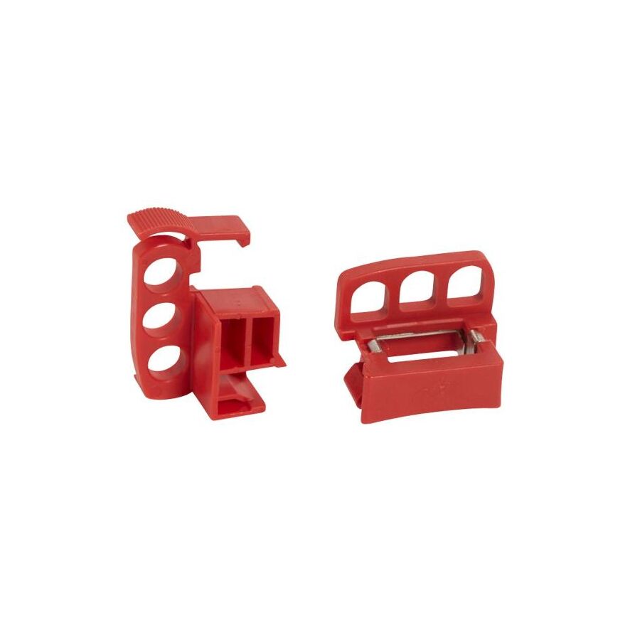
In high-risk Australian industrial environments—from mining operations in Western Australia to manufacturing plants across Victoria—the control of hazardous electrical energy is a non-negotiable safety requirement. Administrative warnings such as danger tags provide information, but they do not prevent re-energisation. True isolation requires a mechanical barrier that makes reconnection physically impossible. The Locking Padlock Open Position facility is the engineered solution that secures a circuit breaker or isolator in the OFF position and prevents manual reclosure. This system allows a safety padlock to be applied only when the device contacts are definitively open, ensuring compliance with Australian isolation standards and eliminating the risk of inadvertent energisation during maintenance.
The mechanical foundation of a Locking Padlock Open Position system is geometric interference. A circuit breaker toggle moves through a defined arc to close internal contacts. The lockout accessory introduces a rigid blocking element that physically obstructs this motion.
When the breaker is switched to OFF, the toggle aligns with a dedicated locking aperture or exposes a void within the accessory housing. The lockout device inserts a reinforced blocking member into this space. If force is applied to the toggle while locked, the applied torque is transferred into the locking accessory and padlock shackle rather than the internal latching mechanism. Professional-grade locking accessories are manufactured from hardened steel or glass-filled engineering polymers designed to resist shear forces without deformation. This ensures that the toggle cannot move into the ON quadrant of travel, preventing the spring mechanism from re-engaging the contacts.
Under AS/NZS 4836 (Safe working on or near low-voltage electrical installations), a circuit is considered isolated only when it is disconnected from all active conductors and secured against inadvertent reconnection. The ability to apply a padlock in the open position is central to meeting this definition.
The standard requires positive contact indication, meaning the position of the breaker must be clearly visible before and after the lock is applied. A compliant Locking Padlock Open Position system does not obscure the position indicator window or the toggle marking. The operator must visually confirm that the device is in the “O” (Open) state prior to securing the padlock. Devices that permit locking while energised present a safety hazard and do not satisfy the intent of isolation requirements.
Modern industrial circuit breakers incorporate trip-free mechanisms, meaning that internal protection functions operate independently of handle position. The Locking Padlock Open Position accessory does not interfere with protective tripping capability; instead, it enforces a zero-energy state downstream during maintenance.
By mechanically preventing manual closure, the lockout system removes human error from the equation. In environments where arc flash risk is significant, preventing unintended re-energisation is critical. If a breaker were accidentally closed into a fault during maintenance, the resulting arc event could cause catastrophic injury and equipment damage. The locking mechanism converts the procedural instruction “Do Not Switch On” into a physical impossibility.
Industrial switchboards are exposed to vibration, dust, chemical vapours, and temperature fluctuations. The durability of a Locking Padlock Open Position accessory is therefore a material engineering consideration.
High-quality lockout devices are manufactured from UV-stabilised, impact-resistant polymers or corrosion-resistant metals. These materials maintain structural integrity under repeated installation cycles and environmental stress. The locking aperture must retain dimensional stability to ensure a secure fit with the padlock shackle. Corrosion resistance is particularly important in coastal or chemical processing facilities, where oxidation could compromise removal or reuse.
The locking accessory is one element of a broader Lock Out Tag Out (LOTO) system. Proper procedure requires that the circuit be de-energised, tested for absence of voltage, and verified prior to lock application.
Multiple personnel may require isolation on a single circuit. In such cases, scissor hasps expand a single locking point into multiple padlock positions, allowing each worker to apply an individual lock in accordance with the “One Person, One Lock” principle. The Locking Padlock Open Position facility must be dimensionally compatible with standard industrial padlock shackles, typically 6mm diameter, to ensure secure engagement.
Clear danger identification tags should be attached directly to the padlock, identifying the authorised person and the reason for isolation. These tags must be durable and legible in harsh environments to maintain procedural compliance.
Effective isolation depends not only on the breaker accessory but also on the quality of the locking hardware. SCHNAP Electric Products supports professional isolation procedures with industrial-grade safety padlocks featuring non-conductive bodies and corrosion-resistant shackles.
Non-conductive materials reduce the risk of the padlock itself becoming an energised point in the event of insulation failure. SCHNAP scissor hasps allow multiple authorised personnel to secure individual locks to a single isolation point. High-visibility danger tags designed for industrial environments maintain legibility under humidity, dust, and oil exposure.
By integrating breaker-specific locking accessories with compliant LOTO hardware, SCHNAP Electric Products supports structured and auditable isolation procedures across industrial sites.
Locking accessories are not universally compatible. Variations in toggle geometry, frame size, and manufacturer design mean that a poorly fitted lockout device may slip or disengage under force.
Professional procurement through a specialised electrical wholesaler ensures correct matching of the Locking Padlock Open Position accessory to the installed circuit breaker model and torque characteristics. Verification against manufacturer specifications prevents site-level improvisation with ill-fitting universal kits, which can introduce serious safety risk.
Selecting tested and compliant accessories ensures that isolation systems function as intended under both routine maintenance and emergency conditions.
The Locking Padlock Open Position facility is a mechanical guarantee of electrical isolation. By applying geometric interference to prevent breaker reclosure, it transforms procedural safety requirements into enforceable physical control. Compliance with AS/NZS 4836 demands that circuits be secured against inadvertent reconnection, and a correctly specified locking accessory fulfils this obligation. When integrated within a structured LOTO system and supported by durable padlocks and identification hardware, it delivers a verifiable zero-energy state for maintenance personnel. In industrial environments where the consequences of re-energisation are severe, engineered isolation is not optional—it is fundamental to safe operation.
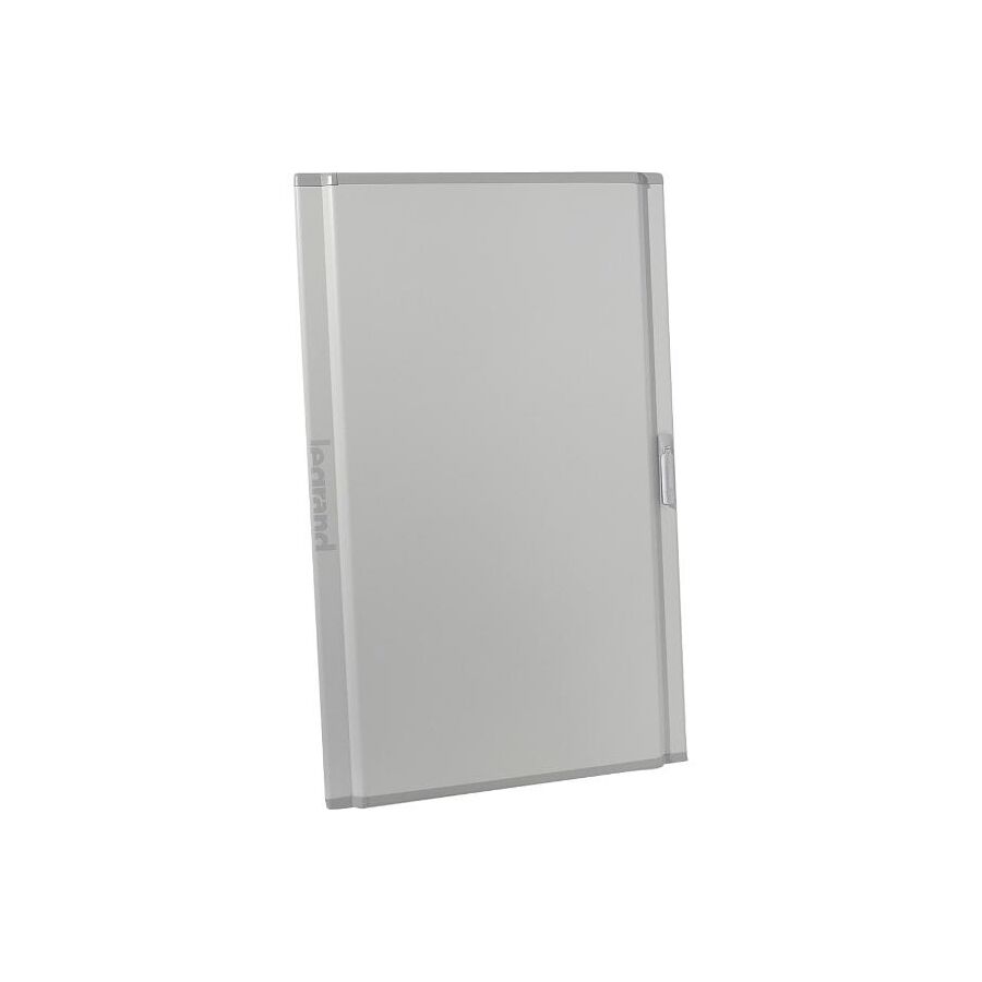
In modern Australian commercial and institutional developments, electrical switchboards are increasingly visible within plant rooms, atriums, and publicly accessible service corridors. They are no longer hidden utility assets but integrated architectural elements. In these environments, enclosure design must satisfy both mechanical performance and aesthetic expectations. The Metal Curved Enclosure Door provides a structural and visual upgrade over traditional flat-panel doors. Beyond its architectural appeal, the curved geometry enhances rigidity, improves gasket compression uniformity, and supports compliance with low-voltage assembly standards. For panel builders and facility managers, it represents a deliberate engineering choice that aligns performance, durability, and design continuity within high-specification projects.
The primary structural advantage of a Metal Curved Enclosure Door lies in geometric stiffening. A flat sheet of 1.5mm or 2.0mm steel relies on welded stiffener rails to resist flexural deformation. Without reinforcement, flat panels are susceptible to oil-canning and deflection under applied force.
By introducing a continuous radius across the door profile, the second moment of area increases perpendicular to the vertical axis. This curvature significantly enhances resistance to bending and buckling without requiring excessive internal bracing. The result is a door that feels mechanically solid during operation and maintains dimensional stability across full-height installations, often exceeding 2000mm. Improved rigidity also ensures consistent compression of perimeter gaskets, preserving IP-rated sealing performance across the entire frame.
Uniform gasket compression is critical to maintaining environmental protection. In flat doors, uneven torque or structural bowing can create micro-gaps that compromise ingress protection ratings such as IP55.
The Metal Curved Enclosure Door distributes closing forces more evenly due to its inherent structural stiffness. When combined with multi-point latching systems, this geometry ensures consistent pressure along the sealing surface. This protects internal components from dust ingress and moisture exposure, particularly in plant rooms or semi-exposed installations. Maintaining sealing integrity supports long-term reliability of circuit breakers, control devices, and metering equipment housed within the assembly.
Compliance with AS/NZS 61439 requires that low-voltage switchgear assemblies maintain mechanical strength and enclosure integrity under specified operating conditions. A structurally rigid door contributes directly to meeting these performance criteria.
A curved profile also provides additional internal clearance compared to a flat-panel equivalent. The apex of the curvature can create an additional 30mm to 50mm of usable space within the enclosure.
This volumetric gain is significant when mounting door-installed devices such as Human Machine Interfaces (HMIs), power quality analysers, digital meters, selector switches, and pilot indicators. In flat-door assemblies, rear-mounted components may clash with internal escutcheons or breaker handles. The curved geometry creates additional depth without increasing the footprint of the enclosure itself. This allows for efficient component integration while preserving valuable floor space in compact switchrooms.
The geometry of a curved door requires a specialised latching mechanism to ensure even compression against the enclosure frame. A single cam lock operating in one plane may not provide sufficient closing force distribution.
Professional-grade Metal Curved Enclosure Door systems utilise rod-latch mechanisms. An ergonomic swing handle actuates vertical rods that engage at multiple points along the frame. This multi-point locking arrangement ensures consistent sealing pressure and prevents localised deformation. Flush-mounted or recessed handles maintain the clean architectural profile and reduce snag hazards in high-traffic environments.
Because the enclosure door is a large conductive steel surface, it must be effectively bonded to the main earth bar. In the event of a phase-to-door fault, low-impedance bonding ensures rapid operation of upstream protection devices.
Flexible braided earth straps provide mechanical continuity while accommodating door movement. Correct earthing is essential for safety compliance and must not be compromised by hinge orientation or door modification.
The rear surface of the door often serves as an information and accessory mounting zone. SCHNAP Electric Products supports panel builders with installation accessories that complement curved door assemblies.
Flexible self-adhesive document holders can conform to the gentle radius of the door interior, protecting single-line diagrams and circuit schedules from dust and moisture. Braided earth straps provide reliable bonding between door and chassis. Door-operated switches can be installed to activate internal LED lighting when the enclosure is opened, improving maintenance visibility and safety.
By integrating structural enclosures with compliant mounting and safety accessories, SCHNAP Electric Products supports professional switchboard construction aligned with Australian standards.
Beyond structural performance, the Metal Curved Enclosure Door enhances visual integration within premium commercial environments. Powder-coated finishes, typically in RAL 7035 or custom corporate colours, benefit from the curvature’s ability to diffuse reflected light.
The curved profile softens the industrial appearance of the cabinet and reduces the visual prominence of minor surface imperfections. In publicly visible installations such as universities, hospitals, and corporate offices, this refined appearance allows the switchboard to align with the broader architectural language rather than appearing purely utilitarian.
Curved doors are not universally interchangeable across enclosure systems. They are typically associated with specific modular switchboard ranges and require compatible hinges, frame geometry, and latching hardware.
Professional procurement through a specialised electrical wholesaler ensures correct specification of reversible hinges, locking assemblies, and sealing components. Verification of compatibility with the enclosure frame prevents site-level modifications that could compromise structural integrity or compliance with assembly certification.
Correct sourcing ensures that the Metal Curved Enclosure Door integrates seamlessly with the switchboard structure and maintains the performance characteristics defined under AS/NZS 61439.
The Metal Curved Enclosure Door represents the convergence of structural engineering and architectural refinement. Its geometric stiffening improves rigidity and sealing consistency, while its internal volumetric advantage supports advanced device integration. Compliance with Australian low-voltage assembly standards depends on enclosure integrity, and the curved profile enhances that mechanical performance. When combined with appropriate earthing, multi-point locking, and professional accessory integration, it delivers a switchboard solution that is robust, compliant, and visually aligned with contemporary infrastructure projects. In high-specification installations, enclosure design is not merely aesthetic; it is structural, functional, and safety-critical.

In Australian industrial power distribution systems, isolation is not merely a mechanical function but an integrated control event. From mining operations in Western Australia to advanced manufacturing facilities in South Australia, the Moulded Case Circuit Breaker (MCCB) serves as the primary isolation device for motors and distribution circuits. However, modern Motor Control Centres (MCCs) require coordinated signalling between manual isolation and automated control logic. The Rotary Handle Auxiliary Contact provides this interface by translating the rotational movement of the handle shaft into a controlled electrical signal. Unlike internal auxiliary contacts that directly monitor breaker pole status, this accessory interacts with the cam mechanism of the rotary handle, delivering timing-sensitive “Early Break” or position indication signals essential for controlled load shedding and protection coordination.
The operation of a Rotary Handle Auxiliary Contact is governed by cam geometry within the handle assembly. When an operator rotates the handle from ON to OFF, the internal breaker mechanism follows a defined mechanical throw sequence.
The auxiliary contact is engineered to change state at a specific angular position of the cam. In Early Break configurations, the auxiliary contact opens before the main power poles separate. This millisecond lead time allows downstream contactors to drop out prior to the MCCB interrupting load current. From an electrical coordination perspective, this protects the breaker contacts from unnecessary arc wear and ensures that routine switching duties are handled by devices designed for frequent operation.
By controlling the sequence of signalling relative to mechanical rotation, the Rotary Handle Auxiliary Contact supports structured shutdown logic and reduces stress on protective equipment.
In modern control architectures, auxiliary signalling circuits typically operate at 24V DC and low milliamp currents to interface with PLC digital input modules. At these current levels, contact material performance becomes critical.
Standard silver-alloy contacts may suffer from oxidation-induced resistance in low-energy applications. Professional rotary handle auxiliaries incorporate gold-flashed or wiping-action contacts to maintain signal integrity. The wiping motion mechanically cleans the contact surfaces during each operation, ensuring consistent conductivity and accurate PLC status recognition.
Reliable signalling prevents false isolation states, unintended lockouts, or control system misinterpretation. In safety-critical environments, the accuracy of the isolation status signal is as important as the mechanical disconnection itself.
Compliance with AS/NZS 60947-5-1 requires that auxiliary control devices meet defined performance and endurance criteria, ensuring suitability for industrial control circuits.
Rotary handles often utilise variable depth shafts to connect door-mounted handles to internal MCCBs. The performance of the auxiliary contact depends on correct shaft alignment and cam engagement.
If the shaft length is incorrectly cut or misaligned, the cam may not fully actuate the auxiliary plunger, resulting in incomplete state change. For shaft extensions exceeding 400mm, support brackets are recommended to prevent deflection or oscillation. Mechanical instability can cause signal “flutter,” where the auxiliary contact intermittently changes state during handle rotation.
High-quality assemblies incorporate rigid mounting points or locking clips to ensure that the auxiliary block remains firmly positioned against the cam profile. Accurate tactile feedback from the handle should correspond precisely with electrical state transition.
Although the auxiliary contact is typically mounted behind the enclosure door, the rotary handle shaft penetrates the enclosure boundary. Maintaining ingress protection is essential to preserve overall switchboard rating.
Sealing gaskets around the shaft penetration point must remain intact to achieve enclosure ratings such as IP65. Auxiliary contact housings are generally moulded from high-grade thermoplastics that resist tracking and absorb mechanical shock generated by rapid handle movement.
In outdoor or humid installations, condensation management within the handle assembly is critical. Proper positioning of auxiliary terminals prevents moisture accumulation from bridging conductors and compromising signalling reliability.
Correct wiring of the Rotary Handle Auxiliary Contact requires structured cable routing to avoid interference with the rotating shaft. Fine-gauge control conductors, typically 0.75mm², should be terminated with bootlace ferrules to ensure secure and consistent clamping.
Cable management solutions must provide adequate slack to accommodate door movement while preventing strain on terminals. Service loops secured with spiral wrap or adhesive mounting bases reduce mechanical stress and prevent entanglement with the rotating mechanism.
Testing of auxiliary timing relative to main pole operation should be performed during commissioning to verify Early Break sequencing and PLC logic alignment.
SCHNAP Electric Products supports professional installation of rotary handle auxiliaries through precision termination and cable management accessories. Bootlace ferrules provide secure termination of flexible control wiring, reducing the risk of loose strands contacting enclosure surfaces.
Spiral wrap and mounting bases assist in creating structured service loops that protect wiring from mechanical wear. Multimeter test leads and diagnostic accessories enable commissioning engineers to confirm auxiliary operation and signal timing relative to breaker actuation.
By integrating mechanical signalling components with compliant wiring and verification tools, SCHNAP Electric Products contributes to reliable and auditable isolation systems within Australian motor control centres.
Rotary handle auxiliaries are manufacturer-specific and model-dependent. Variations exist between direct rotary handles and extended shaft assemblies, as well as between breaker series. Incorrect selection may result in mechanical incompatibility or improper timing sequence.
Professional procurement through a specialised electrical wholesaler ensures compatibility with the installed MCCB series and confirmation of required contact configuration (NO, NC, or changeover). Verification of cam diagrams and timing characteristics prior to installation prevents site-level improvisation and reduces commissioning delays.
Correct specification ensures that the Rotary Handle Auxiliary Contact performs as intended within the broader protection and control scheme.
The Rotary Handle Auxiliary Contact is a critical interface between manual isolation and automated control logic. By leveraging cam kinematics to deliver Early Break or position indication signals, it coordinates mechanical switching with PLC-based control strategies. Compliance with Australian control device standards, combined with reliable low-energy contact performance, ensures accurate isolation feedback. When installed with structured wiring practices and supported by professional accessory integration, it transforms a simple rotary motion into a verifiable safety and control event. In industrial switching systems, effective isolation is not only about separating contacts; it is about synchronising mechanical action with intelligent control.

SCHNAP Electrical Wholesaler - clear, upfront pricing that professional electricians trust

Get what you need in seconds. SCHNAP electrical wholesaler makes ordering quick and simple

Fast delivery anywhere - that's guaranteed. SCHNAP electrical wholesalers ship nationwide with same-day dispatch

Track your order every step of the way. SCHNAP electrical wholesale keeps you updated from click to delivery

SCHNAP is Australia's premier electrical wholesaler and electrical supplies, marketing thousands of quality products from leading brands. Trusted for nearly two decades by licensed electricians, contractors, and engineers, our range covers everything from basic electrical components to complex industrial electrical equipment
Our key categories include: LED lighting, designer switches, commercial switchboards, circuit protection, security systems & CCTV, and smart home automation
All products are certified to Australian standards (AS/NZS), backed by our 30-day, no-questions-asked return policy. Our expert technical team helps you quickly source the right solution for any residential, commercial, or industrial project, with daily dispatch from our Sydney electrical warehouse delivering Australia-wide
SCHNAP offers the most comprehensive electrical product range, with full technical specifications, application details, installation requirements, compliance standards, and warranties — giving professionals total confidence in every purchase


