

Kingsgrove Branch:


Send us a photo and our team will help identify it.

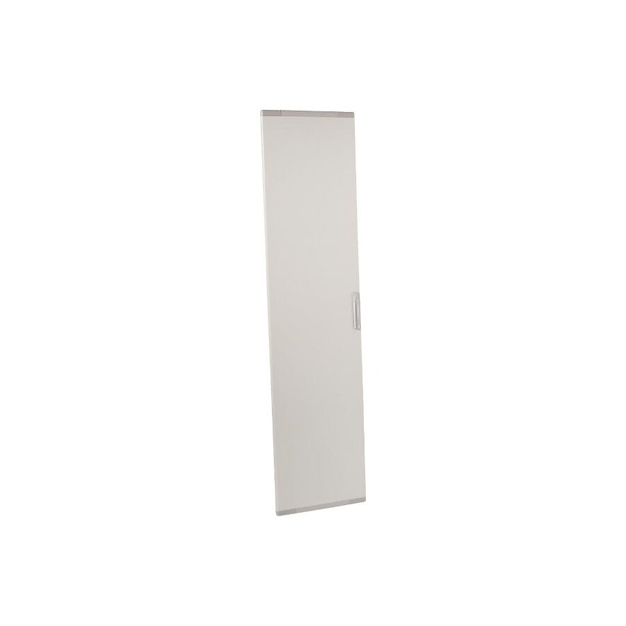
In Australian low-voltage distribution systems—commercial towers, mining operations, data centres and industrial facilities—switchboard integrity is fundamental to operational reliability.
Within the XL³ modular switchboard system, cable management is a critical structural element. High-current feeders and outgoing circuits require a segregated vertical pathway separate from functional units.
The XL³ Cable Sleeve Door encloses this dedicated cable zone, contributing to thermal control, arc fault containment and compliance with AS/NZS 61439 and AS/NZS 3000.
High-current conductors generate heat through resistive losses (I²R).
If cable bundles are placed adjacent to protective relays or MCCBs without segregation, internal ambient temperature rises can cause:
• Breaker derating • Nuisance tripping • Reduced component lifespan
The cable sleeve provides a defined vertical compartment that:
• Physically separates cable runs from device columns • Promotes chimney-style natural convection • Encourages upward thermal airflow • Maintains predictable internal temperature distribution
When properly ventilated, the sleeve assists in dissipating heat without exposing functional units to concentrated thermal load.
AS/NZS 61439 defines internal separation levels (Form 1 through Form 4b).
The XL³ Cable Sleeve Door plays a role in achieving higher forms of segregation by isolating:
• Busbars • Functional units • Cable terminations
By enclosing the cable zone, the door limits arc propagation in the event of a termination failure.
If an internal arc occurs within the sleeve, the enclosure directs pressure and energy away from the operator interface, enhancing personnel safety.
Robust hinge systems and secure latching prevent door blow-out under dynamic pressure conditions.
The cable sleeve door must maintain rigidity over full cabinet height, often 1800mm to 2000mm.
Uniform structural stiffness ensures:
• Even gasket compression • Reliable IP rating • Stable mechanical operation
Multi-point locking systems or upgraded swing handles provide secure closure and improved access control.
SCHNAP Electric Products supports these installations with:
• Quarter-turn locks • Master-key compatible handles • Stainless steel cable ties • Saddle clamps for internal strain relief
Proper internal cable anchoring prevents terminal stress and maintains organised routing within the sleeve.
Depending on configuration, the cable sleeve door contributes to IP43 or IP55 enclosure ratings.
Polyurethane foam gaskets compress against the frame to prevent:
• Dust ingress • Moisture intrusion • Air leakage disrupting thermal design
A compromised seal can alter airflow patterns and create localised overheating.
Uniform compression along the door perimeter is essential to maintaining environmental protection.
A metal cable sleeve door is classified as an exposed conductive part.
Under AS/NZS 3000, it must be bonded to the main earth system.
Flexible braided earth straps from SCHNAP Electric Products provide:
• Low impedance continuity • High flexibility for repeated opening cycles • Secure connection between door and earth bar
This bonding ensures rapid fault clearing if a live conductor contacts the enclosure.
The XL³ system is modular, offering multiple heights and widths (e.g., 300mm or 400mm cable sleeve sections).
Correct selection depends on:
• Cabinet height • Section width • Required form of separation • Locking mechanism type • IP rating target
Incorrect door sizing compromises enclosure integrity and separation compliance.
Specialised electrical wholesaler assist in verifying compatibility with frame dimensions and panel configuration.
SCHNAP Electric Products enhances cable sleeve installations with:
• Stainless steel cable restraints • Heavy-duty saddles • Document holders for single-line diagrams • Arc flash hazard labels • Bonding accessories
Clear documentation mounted inside the sleeve door ensures compliance and operational clarity during maintenance.
The XL³ Cable Sleeve Door is a structural and safety-critical element within modular switchboard assemblies.
By segregating high-current conductors, supporting thermal airflow and contributing to higher forms of separation, it strengthens overall assembly integrity.
When properly bonded, sealed and supported with compliant accessories from SCHNAP Electric Products, it ensures safe, durable and standards-aligned distribution infrastructure.
In low-voltage distribution engineering, structured segregation defines safety and reliability.
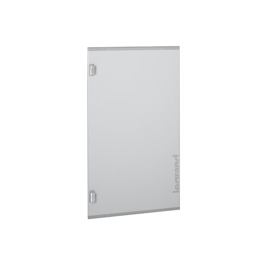
In Australia’s demanding industrial conditions—mining sites, refineries, processing plants and coastal infrastructure—the enclosure protecting switchgear must withstand environmental extremes.
The IP55 Metal Door for XL³ 800 Cabinet is engineered to provide high-level ingress protection and mechanical resilience within the modular XL³ 800 cabinet system.
Designed in accordance with AS/NZS 61439 and AS/NZS 3000, it ensures that internal distribution equipment operates within tested environmental parameters.
IP55 classification provides:
• Protection against dust ingress sufficient to prevent harmful deposits • Protection against water jets from any direction
Achieving this rating across a full-height cabinet door requires precision gasket engineering.
The door features a continuous robot-applied polyurethane (PU) foam gasket.
This seamless bead eliminates join points that could allow water tracking.
When the latch system engages, the gasket compresses against the cabinet frame, forming a uniform seal.
The door’s reinforced profile increases longitudinal stiffness, preventing flexing between locking points and maintaining consistent compression across the entire perimeter.
IP55 performance depends on uniform pressure.
Multi-point locking systems draw the door tight at the top, centre and bottom simultaneously.
Turning the handle drives internal rods into the frame, ensuring even seal compression.
The heavy-gauge sheet steel construction enhances mechanical durability and supports IK-rated impact resistance (commonly IK10 under IEC 62262).
Surface protection typically includes:
• Cataphoresis corrosion treatment • Thermosetting epoxy-polyester powder coating (RAL 7035)
This coating system resists corrosion in humid and salt-laden environments.
Sealed enclosures restrict airflow.
Unlike ventilated doors, an IP55 metal door prevents natural convection cooling.
Engineers must calculate internal temperature rise based on component heat dissipation.
Key factors include:
• Breaker I²R losses • Ambient temperature • Cabinet size • Component density
If internal temperature exceeds rated limits, circuit breakers may require derating.
Proper thermal analysis ensures compliance with equipment operating specifications and prevents nuisance tripping.
Under AS/NZS 3000, metal doors must be bonded to earth.
If a live conductor contacts the door, fault current must return to earth and trip protective devices instantly.
SCHNAP Electric Products supports compliant bonding with:
• Braided earth straps (tinned copper) • Door bonding kits • Earthing studs
These ensure reliable continuity between the door and the main earth bar.
The interior surface of the metal door provides mounting space for documentation and accessories.
SCHNAP Electric Products complements the installation with:
• Self-adhesive document holders for single-line diagrams • Cabinet lighting systems • Door-operated light switches • Cable management accessories
These additions enhance maintenance safety and operational clarity.
Proper earthing, lighting and documentation storage ensure the cabinet remains service-friendly without compromising its environmental rating.
The XL³ 800 cabinet system is modular.
The IP55 metal door is reversible, allowing hinge orientation to be changed on site.
This flexibility accommodates room layout constraints and safe egress planning without affecting sealing performance.
Correct selection depends on:
• Cabinet height (e.g., 1400mm, 1900mm, 2000mm) • Cabinet width (600mm, 800mm) • Lock type (keyed or handle insert) • Required IP rating
Mismatched dimensions can halt panel assembly.
Specialised electrical wholesaler verify frame compatibility and ensure supply of the correct door configuration.
The IP55 Metal Door for XL³ 800 Cabinet serves as the primary environmental barrier protecting industrial switchgear.
Through precision gasket compression, multi-point locking and robust steel construction, it shields internal components from dust, water jets and mechanical impact.
When installed with compliant earthing and accessory systems from SCHNAP Electric Products, it forms a durable, safe and standards-compliant enclosure solution for Australian industrial infrastructure.
In industrial distribution systems, the enclosure is protection—and the door defines its strength.

Across Australia’s harsh climatic zones—cyclonic northern regions, arid mining belts and coastal industrial corridors—the integrity of the earthing network determines infrastructure survivability.
When lightning strikes or high-voltage faults occur, the greatest risk is not simply current magnitude, but voltage difference between conductive systems. This phenomenon, known as Earth Potential Rise (EPR), can create lethal touch voltages and destructive flashovers.
Equipotential Bridging Bars are engineered to eliminate these dangerous voltage gradients by bonding multiple earthing systems into a unified low-impedance node.
They are fundamental to compliance with AS/NZS 1768 and AS/NZS 3000.
During a lightning event, a down-conductor can inject tens or hundreds of kiloamps into the lightning earth electrode.
Because of conductor impedance, that electrode may instantly rise to thousands of volts relative to other earthing systems.
Without equipotential bonding:
• Side-flashing may occur • Equipment insulation may fail • Sensitive electronics may be destroyed • Personnel may be exposed to hazardous touch voltage
Equipotential Bridging Bars interconnect:
• Electrical protective earth (PE) • Lightning protection system (LPS) earth • Telecommunications signal reference ground • Structural steel bonding
The goal is simultaneous potential rise across all bonded systems, eliminating voltage differential.
For lightning events, inductance dominates over resistance.
Because lightning has a rapid rise time, the governing relationship is:
V = L × di/dt
This means bonding conductors must be:
• Short • Straight • Wide • Low inductance
Heavy copper bars and flat copper tapes are preferred to reduce surge impedance.
AS/NZS 1768 requires equipotential bonding between systems, particularly in structures with lightning protection.
In noise-sensitive facilities such as data centres, direct DC bonding between “clean” signal earth and “dirty” lightning earth may create ground loop interference.
In these cases, bridging bars often support:
• Transient Earth Clamps (TEC) • Spark gaps • Surge isolation devices
Under normal conditions, systems remain isolated.
When surge voltage exceeds a breakdown threshold, the clamp conducts and equalises potential instantaneously.
Once the surge dissipates, isolation is restored.
The bridging bar acts as the mounting and bonding manifold for these devices.
Equipotential Bridging Bars must be manufactured from high-conductivity copper.
Common grades include:
• C11000 electrolytic copper • Oxygen-Free High Conductivity (OFHC) copper
In coastal or industrial environments, corrosion resistance is essential.
Tin-plated copper bars are preferred because:
• Tin resists sulphur and salt exposure • Surface oxidation is minimised • Contact resistance remains low
Fixings must be stainless steel or compatible alloys to prevent galvanic corrosion.
All bolted joints must maintain low impedance for the life of the installation.
Lightning impulses may exceed 200kA peak current.
The cross-sectional area of the bridging bar must withstand:
• Thermal rise during impulse • Electrodynamic forces • Mechanical stress
Typical bar dimensions may include:
• 50mm × 6mm • 75mm × 10mm • 100mm × 10mm
Engineering calculations must confirm that current density remains within safe limits and that temperature rise does not exceed cable insulation thresholds.
A bridging bar must remain electrically isolated from unintended conductive surfaces.
It cannot be mounted directly onto steel enclosures or structural members.
SCHNAP Electric Products supports compliant installation with:
• Red DMC standoff insulators • Heavy-duty copper lugs • Disconnect links • Conductive jointing compound • Spring washers for vibration resistance
Standoff insulators provide:
• High dielectric strength • Mechanical rigidity • Secure separation from mounting surfaces
Disconnect links allow individual earth electrodes to be isolated during periodic testing without dismantling the entire bonding network.
Bridging bars must support ongoing verification including:
• Earth resistance testing • Continuity testing • Surge protection inspection
Low-resistance joints are critical.
Gas-tight bolted connections, properly torqued and treated with conductive compound, ensure long-term reliability.
Undersized brass bars or decorative “earth strips” are unsuitable for lightning bonding applications.
Correct selection requires:
• Verified copper purity • Adequate cross-sectional area • Pre-drilled hole pattern compatibility • Compliance with AS/NZS standards
Specialised electrical wholesalers assist in selecting bridging bars suited to:
• Telecommunications facilities • Industrial plants • Healthcare facilities • Data centres • Mining operations
SCHNAP Electric Products complements these systems with compliant termination and mounting accessories to maintain low impedance and long-term durability.
Equipotential Bridging Bars unify separate earthing systems into a single, coordinated safety network.
By eliminating dangerous voltage gradients and managing transient surge impedance, they protect infrastructure and personnel during lightning and fault events.
When engineered in accordance with Australian standards and installed with robust isolation and termination accessories from SCHNAP Electric Products, they form the foundation of resilient electrical infrastructure.
In lightning protection engineering, unity of potential is unity of safety.
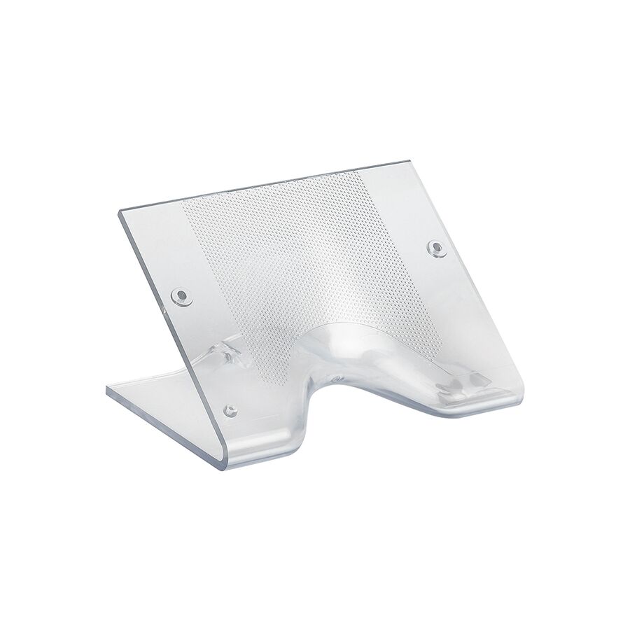
In modern Australian commercial environments—glass-walled offices, heritage restorations and open-plan workspaces—traditional wall-mounted intercom placement is often impractical or architecturally restricted.
The Classe 300 Table-Top Accessory Support provides a purpose-built desktop mounting solution for the Classe 300 video internal unit, enabling secure access control without altering building fabric.
Designed for structured cabling integration and ergonomic optimisation, this accessory converts a wall-based intercom into a stable, desk-mounted console while maintaining full 2-wire bus functionality.
LCD intercom screens are engineered for vertical viewing. When placed flat on a desk, contrast and image clarity degrade due to viewing angle limitations.
The table-top support resolves this through precise geometric inclination, typically between 40° and 45°.
This angle:
• Aligns the display with seated eye level • Preserves colour accuracy • Maintains contrast ratio • Optimises touchscreen interaction
The base is weighted and fitted with anti-slip feet to prevent movement during screen interaction, ensuring stable operation when unlocking doors or answering calls.
The Classe 300 system operates on a 2-wire bus carrying both 27V DC power and high-frequency audio/video data.
A table-top configuration requires flexible connectivity rather than direct wall termination.
The accessory integrates:
• An 8-pin modular interface (RJ45 footprint or proprietary connector depending on model) • Internal PCB routing for impedance matching • Signal continuity protection
Maintaining bus impedance prevents reflection, signal loss or video ghosting.
Properly installed, the desktop unit performs identically to a fixed wall-mounted installation.
The exposed cable between desk and wall presents a vulnerability.
In commercial environments, risks include:
• Foot traffic • Cleaning equipment • Accidental disconnection • Mechanical strain
SCHNAP Electric Products supports secure installation with:
• Cable management spines • Velcro fastening systems • Data faceplates • Mounting blocks • Floor box modules
These accessories protect the “last metre” of cabling and prevent strain on the intercom connection point.
Proper routing along desk legs or within floor boxes eliminates trip hazards while preserving signal integrity.
The table-top accessory is particularly suited to:
• Glass-partitioned meeting rooms • Reception counters • Heritage buildings where wall penetration is prohibited • Shared desks in agile workspaces
In heritage-listed environments, drilling into sandstone or timber panelling may be restricted.
The table-top support allows access control upgrades without structural alteration, preserving architectural integrity while maintaining modern security standards.
Intercom and access control systems installed in commercial settings must align with AS/NZS 3000 for electrical safety and cabling segregation.
When integrated into BMS or security infrastructure, proper structured cabling practices ensure reliable operation and long-term stability.
Correct floor box depth and patch lead selection are essential to prevent cable stress and connector fatigue.
The Classe 300 video unit and table-top accessory are separate components.
Compatibility depends on:
• Specific Classe 300 generation • Connector type • Mounting interface design • Firmware series
Specialised electrical wholesaler verify model compatibility before supply to prevent installation delays.
Accessory kits typically include:
• Desktop support frame • Connection lead • Interface adaptor
Additional structured cabling components may be required depending on site configuration.
Classe 300 Table-Top Accessory Supports are available through professional electrical and security wholesalers specialising in commercial access control systems.
Availability may vary depending on intercom model revision and regional stock levels.
The Classe 300 Table-Top Accessory Support enables flexible access control placement without compromising signal performance or ergonomic usability.
By preserving 2-wire bus integrity, optimising viewing geometry and integrating secure cable management solutions from SCHNAP Electric Products, it delivers a practical and architecturally sensitive solution for Australian commercial fitouts.
In modern workspaces, adaptability is essential—and flexibility begins at the interface.
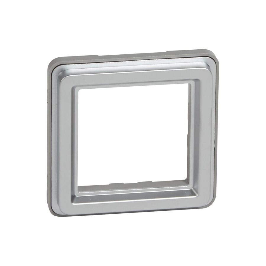
In Australian public infrastructure, durability is not optional. Transport hubs, schools, correctional facilities and public amenities demand electrical accessories that can withstand impact, tampering and environmental exposure.
The Soliroc Adaptor is the critical interface component that enables standard 45mm x 45mm modular mechanisms to be installed inside an IK10-rated vandal-resistant enclosure.
It bridges rugged external protection with modular internal functionality, allowing power, data and control devices to operate safely in high-risk environments.
The Soliroc system is rated IK10 under IEC 62262.
IK10 signifies resistance to 20 joules of impact energy, equivalent to a 5kg object dropped from 400mm.
The adaptor plays a structural role in maintaining this rating.
If a delicate mechanism were mounted directly behind a steel faceplate, impact energy would transfer into the plastic clips and electronic components, causing internal damage.
The Soliroc Adaptor acts as a structural decoupler.
Manufactured from reinforced polymer or die-cast alloy, it:
• Locks the mechanism securely in position • Transfers axial force into the wall box • Bypasses sensitive internal electronics • Maintains alignment under repeated shock
This load-transfer design ensures survivability even after sustained abuse.
Public electrical installations are exposed to:
• High-pressure washdowns • Wind-driven rain • Dust accumulation • Humidity fluctuations
The adaptor forms part of the Soliroc IP55 sealing system.
IP55 provides protection against dust ingress and water jets from any direction.
The adaptor incorporates:
• Integrated sealing membranes • Compression gaskets • Interference-fit geometry • Labyrinth sealing paths
These design elements prevent water tracking via capillary action into live terminals.
At the same time, the adaptor allows full switch actuation and socket access without compromising the environmental seal.
A key advantage of the Soliroc Adaptor is cross-platform compatibility.
It enables installation of 2-module (45mm) mechanisms including:
• Power sockets • Light switches • USB chargers • HDMI outlets • RJ45 data ports • Access control readers
This allows facility managers to standardise on a single modular mechanism range throughout a building while upgrading only public-facing areas to IK10 protection.
Delicate electronic devices remain recessed and shielded within the rugged enclosure.
Durability depends on the entire installation ecosystem.
The Soliroc Adaptor must be anchored to a robust mounting substrate.
SCHNAP Electric Products supports this system with:
• Metal wall boxes • Masonry mounting blocks • IP-rated conduit glands • Solvent cement for sealed conduit entries • Flush-mounting kits • Rendering shrouds
Because Soliroc assemblies reduce available wiring space, angled bootlace ferrules from SCHNAP Electric Products assist in terminating flexible conductors without stressing terminals or compromising sealing integrity.
Proper conduit sealing and mechanical anchoring ensure the IK and IP ratings are preserved at installation level.
The Soliroc faceplate is secured with proprietary security screws such as pin-hex or snake-eye designs.
Once the plate is fixed:
• The adaptor cannot be accessed • Live wiring is inaccessible • Mechanisms cannot be removed without specialised tools
This layered protection prevents vandalism and unauthorised access to live conductors.
Public installations must align with AS/NZS 3000 for electrical safety.
When installed correctly with compliant back boxes and conduit systems, the Soliroc Adaptor contributes to:
• Mechanical protection of live parts • IP-rated environmental sealing • Shock prevention • Safe public interface access
The Soliroc system is modular.
Components are typically supplied separately:
• Support frame • Adaptor • Mechanism • Faceplate
Correct adaptor selection depends on:
• Mechanism type (power, data, control) • Back box depth • Wall construction • Environmental rating requirements
Specialised electrical wholesaler assist in confirming compatibility between adaptor, mechanism and enclosure depth to prevent installation errors.
Soliroc Adaptors are available through professional electrical wholesalers specialising in commercial and public infrastructure solutions.
Availability may vary depending on mechanism compatibility and project-specific configuration requirements.
The Soliroc Adaptor is the engineered interface that allows advanced electrical functionality to survive in hostile public environments.
By transferring impact forces away from sensitive modules, maintaining IP55 sealing and enabling modular versatility, it ensures durability without sacrificing functionality.
When supported with robust mounting and sealing accessories from SCHNAP Electric Products, it forms a resilient, compliant and secure solution for Australian public infrastructure.
In high-risk environments, durability is not optional—it is engineered.
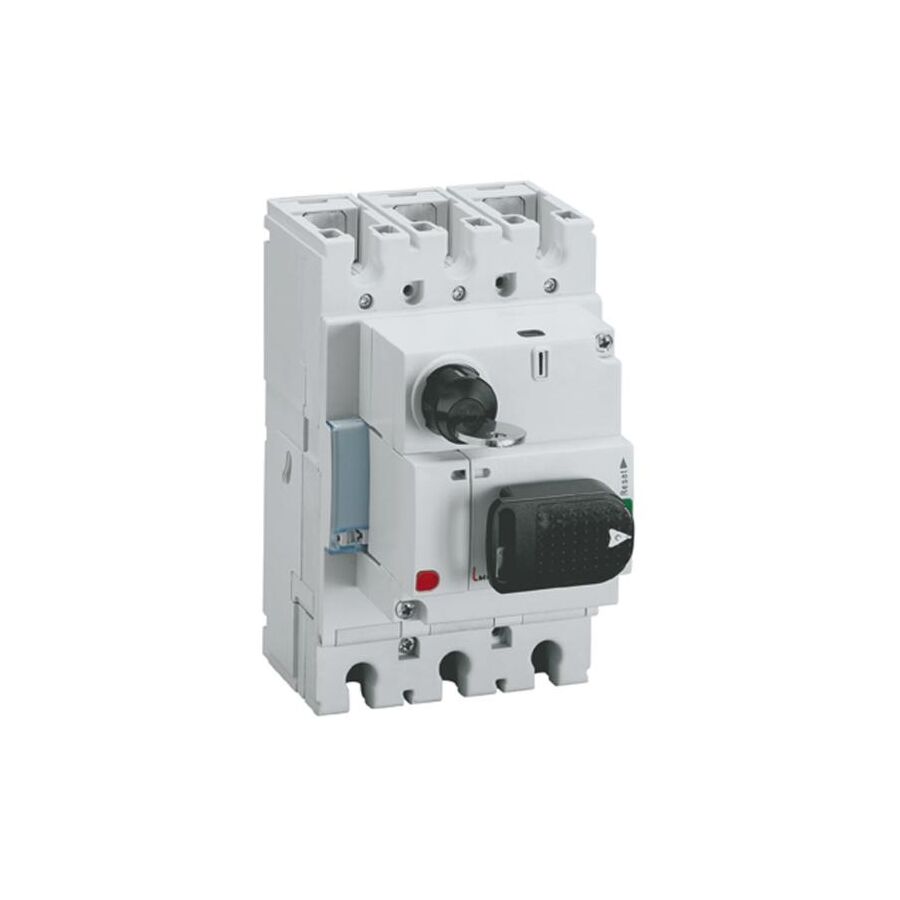
In Australian industrial power systems, the Moulded Case Circuit Breaker (MCCB) is the primary device for overcurrent protection. However, when installed inside enclosed switchboards, the breaker toggle is not directly accessible.
The Thermal Magnetic Rotary Handle provides a safe, door-mounted operating interface that transmits switching motion from the enclosure exterior to the internal breaker mechanism.
Engineered to comply with AS/NZS 3000 and AS/NZS 60947-2, it ensures mechanical isolation, operator safety and environmental sealing.
Large frame MCCBs require significant force to operate due to internal spring mechanisms that rapidly separate contacts during faults.
A rotary handle introduces mechanical advantage using a cam-and-spring design.
When rotated 90 degrees:
• A charging spring stores mechanical energy • The internal mechanism snaps contacts open or closed • Operation remains independent of hand speed
This quick-make / quick-break action prevents contact teasing, which could otherwise cause sustained arcing and contact welding.
The handle typically displays three clear positions:
• ON (I) • OFF (O) • TRIP (centre position)
The mid-position immediately indicates that the breaker has tripped due to overload or short circuit, assisting maintenance diagnostics.
A critical safety feature of the rotary handle is mechanical door interlocking.
When the handle is in the ON position:
• A cam mechanism locks the enclosure door • Access to live internal components is prevented
This ensures compliance with switchboard safety requirements and prevents accidental exposure to live busbars.
Authorised personnel may override the interlock using a concealed defeat mechanism. This override requires deliberate action and a tool, ensuring it cannot occur accidentally.
The rotary handle connects to the breaker via a square steel shaft.
In deep enclosures (400mm to 600mm), precise alignment is essential.
Improper shaft length can cause:
• Binding • Incomplete engagement • Door closure failure • Trip malfunction
High-quality systems incorporate telescopic shafts or floating couplings to allow ±5mm tolerance and compensate for slight panel misalignment during assembly.
This flexibility ensures reliable engagement even when heavy cabling exerts pressure behind the breaker.
The internal mechanism ensures that the external handle reflects the true position of the breaker contacts.
The locking tab for LOTO can only extend when the contacts are fully open.
This provides positive isolation verification, meaning that if a padlock is installed, re-energisation is mechanically impossible.
Under Australian WHS requirements, isolation must be secure and verifiable.
The rotary handle includes a locking tab that accepts padlocks (typically 5mm to 8mm shackle diameter) in the OFF position.
When padlocked:
• Handle rotation is physically blocked • Contacts remain separated • Re-energisation is prevented
Multiple padlocks may be applied using LOTO hasps, enabling group isolation procedures.
This aligns with isolation principles under AS/NZS 4836.
Because the rotary handle penetrates the enclosure door, sealing is critical.
IP-rated gasket systems (commonly IP65) prevent:
• Dust ingress • Moisture penetration • Conductive contamination
SCHNAP Electric Products IP65 gasket kits provide reliable sealing around the handle bezel.
Door reinforcement brackets can also be used to prevent sheet metal flex when operating high-torque mechanisms.
SCHNAP Electric Products supports rotary handle installations with compatible safety and identification accessories including:
• IP-rated sealing gaskets • Lockout/Tagout hasps • Safety padlocks • Engraved legend plates • Traffolyte labels • Door reinforcement brackets
Clear labelling (e.g., “Main Switch DB-1”) ensures unambiguous identification during emergency shutdowns.
Proper cable management and internal segregation accessories maintain compliance and safe installation standards.
Rotary handles are frame-specific.
Correct selection depends on:
• MCCB frame size (125A, 250A, 400A, 630A etc.) • Shaft footprint • Required door depth • Environmental IP rating • Locking configuration
Specialised electrical wholesaler verify compatibility between breaker model and handle kit to ensure safe and compliant installation.
The Thermal Magnetic Rotary Handle transforms a powerful protection device into a controlled and safe operator interface.
By providing mechanical advantage, positive contact indication, door interlocking and Lockout/Tagout capability, it ensures safe switching and isolation in industrial environments.
When supported with SCHNAP Electric Products sealing and identification accessories, it delivers a compliant, durable and professional switchboard solution.
In power distribution, control is safety—and safety begins at the handle.
In high-risk Australian industrial environments—mining, manufacturing, refineries, logistics hubs—electrical isolation is the first and most critical step in hazard control.
Under the Work Health and Safety framework and AS/NZS 4836, strict Lockout/Tagout (LOTO) procedures are mandatory when servicing electrical equipment.
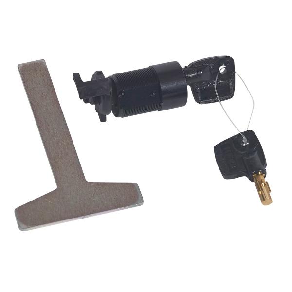
The Direct Handle Locking Accessory is the engineering control that physically prevents re-energisation of a Moulded Case Circuit Breaker (MCCB) or switch-disconnector. It attaches directly to the breaker toggle, securing the device in the OFF position and maintaining a verified zero energy state throughout maintenance.
The core engineering principle behind a direct handle lock is geometric interference.
An MCCB toggle moves through a defined arc when switching from OFF to ON. The locking accessory clamps around the toggle or breaker housing, creating a rigid mechanical barrier that physically blocks this movement.
Industrial breakers—particularly 250A to 630A frames—contain strong internal spring mechanisms. If a locking device lacks structural integrity, it can shear under force.
Professional locking accessories are manufactured from reinforced engineering polymers such as glass-filled nylon or high-impact composites. Some heavy-duty models use powder-coated steel for additional strength.
Once secured with a padlock, the device becomes mechanically integrated with the breaker, making forced operation physically impossible without removing the lock.
AS/NZS 3000 requires that isolation devices be capable of being secured in the open position.
A compliant direct handle locking accessory must allow visual confirmation that the breaker is in the OFF position before locking.
High-quality designs incorporate:
• Clear sight windows • Position indicator cut-outs • Unobstructed access to OFF markings
This ensures technicians can confirm isolation before applying the lock, aligning with formal safe work procedures.
The locking accessory includes a dedicated shackle hole designed to accept standard LOTO padlocks, typically 6mm to 8mm diameter.
When the padlock is inserted:
• The clamping jaws are secured closed • The toggle cannot move • The device cannot be removed
SCHNAP Electric Products safety padlocks are engineered with non-conductive bodies and unique keying systems such as keyed-different or master-keyed options.
High-visibility “Do Not Operate” danger tags attach directly to the padlock shackle, ensuring administrative control accompanies physical isolation.
This combined system satisfies the procedural requirements of AS/NZS 4836 for lockout and tagging.
Direct handle locking accessories fall into two main categories:
OEM-Specific Designed by the breaker manufacturer to fit pre-moulded locking slots. These offer maximum mechanical security and precise tolerances.
Universal Designed with adjustable screw-clamp mechanisms to grip the toggle of various breaker brands. These are ideal in mixed-brand installations.
Universal devices must provide sufficient clamping force to prevent sliding on tapered toggles. A comprehensive lockout kit ensures compatibility across multiple frame sizes.
Switchrooms in industrial facilities are often exposed to:
• Coal dust • Hydraulic fluids • Cleaning solvents • Temperature fluctuations • UV exposure
Standard plastics may crack or degrade in these conditions.
Professional-grade locking accessories are manufactured from chemical-resistant thermoplastics that maintain structural integrity under harsh environmental exposure.
UV-stabilised materials prevent brittleness and colour fading, ensuring long-term reliability.
The locking device forms part of a complete isolation ecosystem.
SCHNAP Electric Products supports industrial safety programs with:
• Safety padlocks (non-conductive bodies) • High-visibility danger tags • Lockout stations • Group lockout boxes • Universal breaker lockout kits
Group lockout boxes allow multiple technicians to secure a single isolation point, ensuring no circuit can be re-energised until every authorised worker has removed their personal lock.
Correct selection of locking accessories depends on:
• Breaker frame size • Toggle geometry • Available mounting clearance • Required shackle diameter • Site LOTO policy
Specialised electrical wholesaler assist facility managers in auditing installed switchgear and selecting compliant locking solutions that align with site-specific safety procedures.
Availability of correct locking accessories is critical to prevent maintenance delays and unsafe workarounds.
The Direct Handle Locking Accessory transforms electrical safety policy into physical reality.
By preventing mechanical movement of the breaker toggle, it guarantees isolation integrity throughout maintenance operations.
When combined with compliant padlocks and tagging systems from SCHNAP Electric Products, it ensures Australian industrial facilities meet regulatory requirements while protecting personnel from the consequences of uncontrolled energy release.
In electrical safety, isolation must be absolute—and physically enforced.
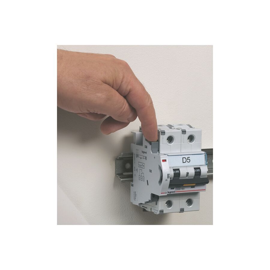
In Australian critical power systems, uninterrupted supply is essential. Data centres, hospitals, transport hubs, and industrial plants rely on Automatic Transfer Switches (ATS) to shift loads between mains and generator supply during grid failure.
For this transition to occur safely, the control system must receive precise positional feedback from the main switching devices. The Auxiliary Changeover Switch provides this essential interface, converting mechanical movement into low-voltage control signals.
Designed in accordance with AS/NZS 60947-6-1 and integrated under AS/NZS 3000, it forms the backbone of ATS interlocking and monitoring logic.
An auxiliary changeover switch is mechanically linked to the primary contactor or circuit breaker. It does not carry load current. Instead, it mirrors the position of the main device.
When the main breaker moves to ON or OFF, a cam or plunger actuates the auxiliary mechanism.
High-quality designs incorporate snap-action switching to ensure:
• Instant contact transition • Minimal contact bounce • Stable signal output • Reliable digital state reporting
Contact bounce can cause false signals to PLCs or generator controllers. Snap-action mechanisms eliminate delayed switching and maintain precise synchronisation with the main device.
Auxiliary changeover switches commonly provide Form C contacts:
• Normally Open (NO) • Normally Closed (NC) • Common (COM)
This configuration enables changeover logic, where one circuit opens as another closes.
Common variants include:
• 1NO + 1NC • 2NO + 2NC • Delayed make or delayed break types
Correct configuration is essential for ATS interlocking sequences.
Auxiliary contacts frequently switch relay coils or control circuit solenoids. These are inductive loads.
When an inductive circuit opens, back electromotive force (Back-EMF) creates a voltage spike. If the auxiliary contact is not rated for AC-15 or DC-13 utilisation categories, arcing can occur, leading to:
• Contact pitting • Surface erosion • Welding • Signal failure
Professional-grade auxiliary changeover switches use silver alloy contacts with arc-resistant geometry to withstand inductive switching cycles reliably.
Modern ATS and BMS systems operate on 24V DC or lower control voltages.
At low voltage, oxidation on contact surfaces can prevent reliable conduction due to insufficient wetting current.
Advanced auxiliary switches incorporate wiping contact action, where contact surfaces slide slightly during closure. This scrubbing action removes oxide layers and maintains low contact resistance.
For ultra-low voltage applications, gold-plated contact options may be specified to further enhance signal reliability.
In generator-backed installations, electrical interlocking prevents simultaneous closure of mains and generator contactors.
A typical arrangement uses:
• NC auxiliary contact of mains device • Series wiring to generator contactor coil
This ensures the generator contactor cannot energise unless the mains breaker is proven open.
This mechanical-electrical interlock enhances system safety and prevents dangerous backfeed conditions.
Auxiliary contacts provide galvanic isolation between high-voltage power circuits and low-voltage control systems.
Their dielectric housing must withstand voltage surges and impulse conditions without flashover into control wiring.
This separation protects PLC inputs, fire systems, and generator controllers from transient faults originating in the main distribution circuit.
SCHNAP Electric Products supports reliable auxiliary installations with compatible mounting and wiring accessories.
High-retention clip mechanisms ensure stable mechanical coupling between auxiliary blocks and main devices.
Bootlace ferrules provide secure termination of fine-stranded control wires, preventing strand bridging between NO and NC terminals.
Cable markers and identification systems ensure every control wire is clearly labelled, simplifying commissioning and future maintenance.
Proper DIN rail support and cable management accessories maintain separation between control and power conductors within the enclosure.
After installation, auxiliary contacts should be verified by:
• Manual breaker operation confirmation • PLC input status verification • Generator controller handshake testing • Interlock functionality simulation
Routine testing ensures reliable feedback during actual power failure events.
The Auxiliary Changeover Switch is the feedback mechanism that allows Automatic Transfer Switch systems to operate safely and intelligently.
By accurately translating mechanical breaker position into control logic signals, it ensures correct sequencing, interlocking, and generator engagement during mains failure.
In critical power systems, reliable feedback is the foundation of continuity and safety.

In Australian healthcare facilities, certain patient treatment rooms require the highest level of electrical protection. These areas are governed by AS/NZS 3003 and are specifically engineered to prevent microshock hazards during invasive or intracardiac procedures.
The Cardiac Arrest Area Sign (commonly aligned with “Cardiac Protected Electrical Area” classification) serves as the formal visual declaration that the room’s electrical infrastructure meets the stringent protection requirements defined by Australian standards.
This signage is not decorative. It is a compliance instrument indicating that enhanced protective measures are installed and commissioned.
The distinction between general electrical safety and medical-grade safety lies in human physiology.
In normal environments, protection is designed to prevent macroshock—external current flow through the body, typically measured in milliamps (mA).
In cardiac procedure environments, conductive medical devices such as catheters may contact heart tissue directly. This bypasses the skin’s natural resistance.
In such conditions, currents as low as 10 microamps (µA) can induce ventricular fibrillation.
A Cardiac Arrest Area Sign indicates that the room includes:
• Enhanced equipotential bonding systems • Low earth resistance infrastructure • Dedicated medical RCD protection (Type 1, <40ms trip) • Line Isolation Monitoring (LIM) systems where required
Only appropriately rated medical equipment—such as Type CF (Cardiac Floating)—should be connected within these zones.
AS/NZS 3003 requires permanent and clearly visible identification of patient areas.
The signage must:
• Be durable and non-removable • Display correct classification wording • Be positioned near socket outlets or at room entry • Match commissioning documentation
Before signage is installed, the area must undergo verification including:
• Equipotential bonding resistance testing (typically <0.1 ohms) • RCD trip time confirmation • Isolation monitoring validation
The presence of the sign confirms the room has passed commissioning and is suitable for cardiac-level electrical protection.
Cardiac-protected areas rely heavily on equipotential bonding.
All exposed conductive parts within the patient vicinity are bonded to a central earth reference point to eliminate voltage potential differences.
This includes bonding of:
• Bed frames • Gas outlets • Equipment rails • Metallic wall structures • Protective earth terminals
The signage communicates that this bonding system is active and verified.
Healthcare environments involve rigorous chemical cleaning. Surfaces are exposed to:
• Sodium hypochlorite (bleach) • Quaternary ammonium disinfectants • Alcohol-based cleaners • UV sterilisation systems
Professional Cardiac Arrest Area Signs are manufactured from:
• Reverse-printed polycarbonate • Engraved multi-layer phenolic laminates (Traffolyte) • Smooth, non-porous materials
These materials resist chemical degradation and prevent bacterial accumulation, supporting infection control requirements.
SCHNAP Electric Products supports compliant medical installations with infrastructure components designed for patient areas.
Medical-grade socket outlets may be colour-coded to distinguish supply sources such as:
• Normal supply • Generator-backed supply • UPS systems
Integrated service panels can incorporate signage directly into the faceplate for hygienic, flush mounting.
Equipotential earth studs provide dedicated testing connection points for biomedical equipment verification.
RCD test switches and status indicators assist in maintaining ongoing compliance and monitoring within cardiac-protected zones.
Incorrect signage can render a treatment room non-compliant during inspection or accreditation audits.
Proper sourcing ensures:
• Correct wording aligned with AS/NZS 3003 • Appropriate colour coding • Durable medical-grade construction • Compatibility with healthcare fitouts
Signage must accurately reflect whether the area is classified as body-protected or cardiac-protected.
The Cardiac Arrest Area Sign represents the visible certification of a high-integrity medical electrical installation.
It confirms that the environment is engineered for the strictest level of patient electrical safety, including microshock protection and equipotential bonding.
In healthcare infrastructure, clear identification is not administrative—it is a critical component of life-safety compliance.
In modern Australian commercial and industrial installations, circuit breakers must do more than respond to overloads and short circuits. Facilities such as data centres, hospitals, workshops, and manufacturing plants require the ability to trip breakers remotely in response to emergency or control system signals.
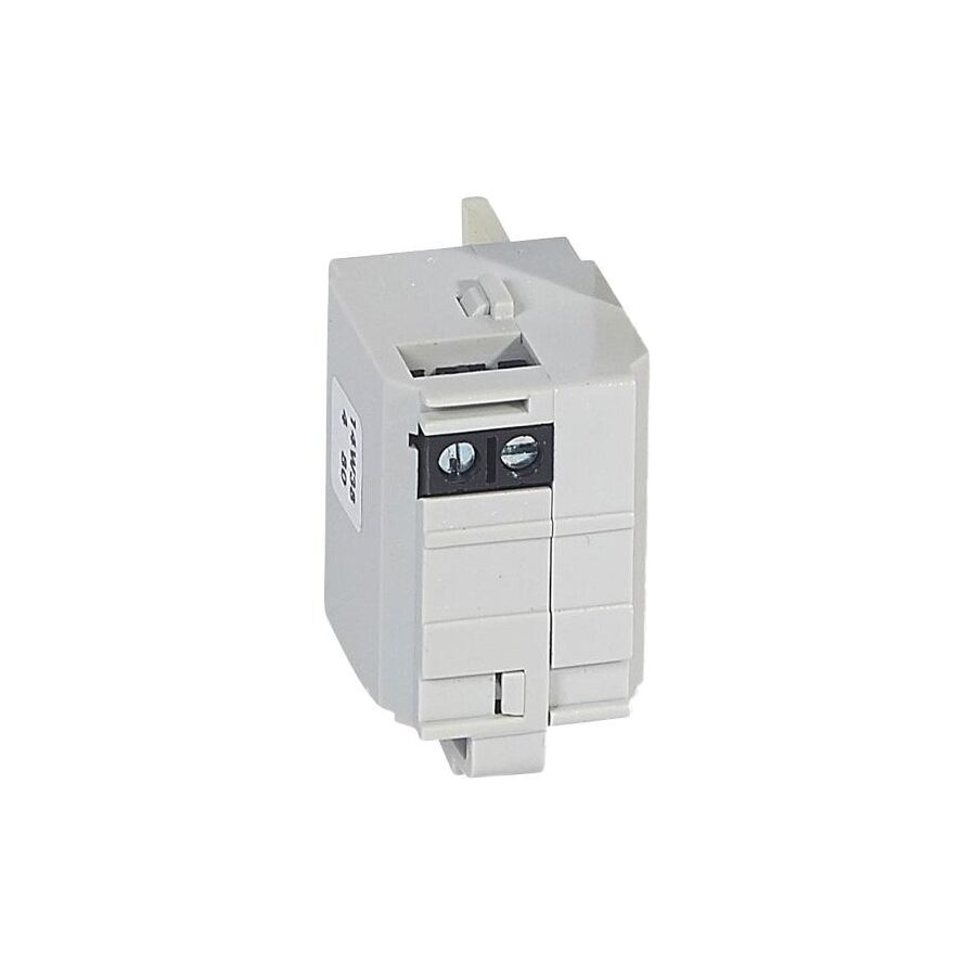
The 24V Shunt Release for DPX³ Circuit Breakers enables this functionality within the DPX³ MCCB platform.
Designed to comply with AS/NZS 60947-2 and integrated in accordance with AS/NZS 3000, the shunt release transforms a passive protection device into an actively controlled isolation point.
A shunt release is a power-to-trip accessory.
Internally, it contains a solenoid coil and armature. When a 24V signal (AC or DC depending on model) is applied, the electromagnetic field drives the armature forward, mechanically striking the breaker’s trip bar.
This action:
• Unlatches the internal mechanism • Opens the main contacts • Forces the breaker into the TRIP position • Removes supply instantly
The coil is designed for impulse duty. Continuous energisation after tripping can cause overheating. For this reason, control circuits typically incorporate an auxiliary contact wired in series to disconnect the coil supply once the breaker opens.
One of the primary applications is integration with building fire systems under AS 1670.
When smoke detection occurs, the Fire Indicator Panel (FIP) sends a 24V DC signal to designated distribution boards.
The shunt release then trips the MCCB supplying:
• HVAC systems • Mechanical ventilation • Smoke control equipment • Non-essential services
Using 24V control aligns with Safety Extra Low Voltage (SELV) practices and avoids routing hazardous 240V control circuits through fire panel interfaces.
In industrial environments, emergency stop circuits require immediate removal of power—classified as a Category 0 stop.
A red mushroom-head emergency stop button is wired to energise the 24V shunt release coil.
When activated, it:
• Trips the upstream MCCB • Removes supply to machinery • Overrides welded contactors • Provides upstream isolation
This ensures rapid shutdown regardless of downstream equipment state.
The shunt release coil must be protected from short-circuit conditions.
Typical installations include:
• DIN-rail fuse holders • Miniature circuit breakers (MCBs) • Interface relays • Control transformers (if voltage conversion required)
Proper circuit protection ensures that a coil fault does not disrupt upstream power distribution.
The shunt release accessory fits into a dedicated compartment within the DPX³ breaker housing.
Correct installation requires:
• Secure mechanical engagement • Verification of armature alignment • Proper routing of flying leads • Identification of control wiring
Control wires must be clearly labelled to indicate that they may remain energised from external sources even when the breaker is OFF.
SCHNAP Electric Products supports remote trip installations with complementary wiring and control accessories.
Bootlace ferrules ensure secure termination of fine-stranded control wires feeding the shunt release coil.
DIN-rail fuse holders provide dedicated protection for the 24V control circuit.
Interface relays assist where signal isolation is required between fire panels and switchboard control wiring.
Spiral wrap and cable management accessories maintain segregation between control circuits and main power conductors within the enclosure.
These components contribute to a safe and organised remote tripping system.
Shunt releases are frame-specific.
A DPX³ 160 model differs mechanically from DPX³ 250 or DPX³ 630 frames. Voltage selection must also match the site control system (24V AC or 24V DC).
Proper specification ensures:
• Mechanical compatibility • Correct impulse force • Reliable breaker actuation • Long-term operational integrity
Incorrect pairing may result in failure to trip or coil damage.
After installation, testing should confirm:
• Correct coil voltage supply • Successful remote trip activation • Auxiliary contact interruption of coil current • Proper breaker reset function
Periodic testing ensures the remote trip system remains functional when required during emergency conditions.
The 24V Shunt Release for DPX³ Circuit Breakers provides essential remote tripping capability for modern safety and control systems.
By enabling fire panel integration, emergency stop functionality, and controlled isolation within compliant switchboards, it enhances operational safety and response time.
In advanced electrical distribution systems, the ability to trip remotely is not optional—it is fundamental to risk management and life safety.

SCHNAP Electrical Wholesaler - clear, upfront pricing that professional electricians trust

Get what you need in seconds. SCHNAP electrical wholesaler makes ordering quick and simple

Fast delivery anywhere - that's guaranteed. SCHNAP electrical wholesalers ship nationwide with same-day dispatch

Track your order every step of the way. SCHNAP electrical wholesale keeps you updated from click to delivery

SCHNAP is Australia's premier electrical wholesaler and electrical supplies, marketing thousands of quality products from leading brands. Trusted for nearly two decades by licensed electricians, contractors, and engineers, our range covers everything from basic electrical components to complex industrial electrical equipment
Our key categories include: LED lighting, designer switches, commercial switchboards, circuit protection, security systems & CCTV, and smart home automation
All products are certified to Australian standards (AS/NZS), backed by our 30-day, no-questions-asked return policy. Our expert technical team helps you quickly source the right solution for any residential, commercial, or industrial project, with daily dispatch from our Sydney electrical warehouse delivering Australia-wide
SCHNAP offers the most comprehensive electrical product range, with full technical specifications, application details, installation requirements, compliance standards, and warranties — giving professionals total confidence in every purchase


Kingsgrove Branch:
Opening hours:
Mon - Fri: 6:30 AM to 5 PM
Saturday: 8:00 AM to 2:00 PM
Sunday: 9:00 AM to 2:00 PM
Closed on public holidays
Jannali Branch:
Closed for Renovations
© 2004 - 2026 SCHNAP Electric Products