




Kingsgrove Branch:
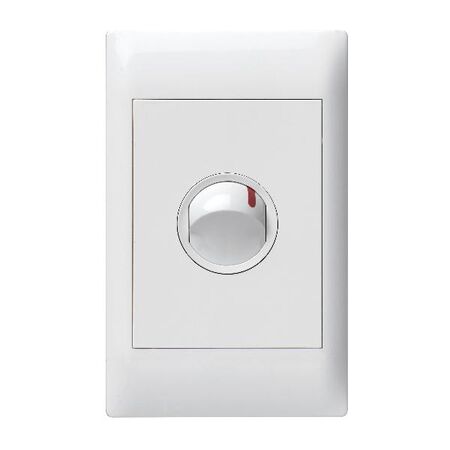
Halfway through wiring a new instantaneous electric hot water circuit for a kitchen reno, a sparky reaches into the van for the usual 10A switch mechanism -- the one that goes in nine jobs out of ten. Then the appliance data plate says otherwise, and it's back to the supplier for something with a bit more headroom.
A switch mechanism isn't just a rocker in a plate -- it's a rated component with a maximum continuous current it can safely make and break, over and over, without the contacts arcing, welding, or degrading early. Fit a mechanism rated below what the circuit actually draws and, in practice, you're looking at premature contact wear, overheating at the terminals, or a switch that simply doesn't survive the load it's asked to control. For general lighting and standard power points this rarely comes up because most stock mechanisms comfortably cover it. It becomes a real decision the moment the circuit is feeding something heavier -- an instantaneous hot water unit, a ducted air conditioner compressor, a workshop machine, or anything else pulling meaningfully more than a light fitting.
The load itself usually isn't hard to find -- it's on the appliance data plate, the circuit design, or the switchboard schedule. The part that trips people up is translating that number into the right switch mechanism off the shelf, especially when the job is moving fast and the habit is to grab whatever's in the kit.
Most switch mechanisms sold for general use in Australia sit somewhere across a fairly predictable spread of ratings, and each one tends to map to a familiar type of circuit. As a general rule, the table below reflects how these ratings are typically applied on the tools -- always cross-check against the actual appliance data plate and circuit design rather than relying on rating alone.
| Rating | Typically Used For |
|---|---|
| 10A | General lighting circuits, low-draw fixtures |
| 15A -- 16A | Heavier lighting loads, small fixed appliances |
| 20A | Standard power circuits, mid-size fixed appliances |
| 32A | Instantaneous hot water units, single-phase workshop equipment |
| 40A | Isolator-tier duty -- ducted AC compressors, larger fixed loads |
Double pole mechanisms are worth calling out separately here too -- double pole isn't a higher rating, it's a different function (breaking both active and neutral rather than just active). A double pole 10A switch mechanism is still a 10A mechanism; it just isolates more completely. Don't assume "double pole" automatically means "handles more current."
Back to the hot water circuit -- once the data plate confirms the higher draw, the fix is simply moving up to a mechanism built for it, like a 32A single-way switch mechanism or, for genuinely heavier fixed loads such as a ducted AC compressor, a 40A isolator-tier mechanism. If the isolation itself needs to break both active and neutral, a double pole bi-lock mechanism covers that at the 16A tier. None of this changes how the mechanism gets fitted -- safely replacing the switch mechanism itself is the same process whether it's a 10A or a 40A unit, the rating is just what you confirm before you start.
Standard power circuits sit comfortably at 20A, covered well by something like a 20A switch mechanism, and for socket-style outlets rather than a switch action, a 10A socket mechanism runs the same rating logic in a different form factor. Every switch mechs range at Schnap covers this full spread, so it's rarely a stock issue -- it's a matter of confirming the number before ordering.
Grabbing whatever's in the kit. The 10A switch mechanism is the default in most vans because it covers the majority of jobs -- but "majority" isn't "all", and a hot water or AC circuit is exactly where that habit catches people out.
Treating double pole as a higher rating. Double pole changes what gets isolated, not how much current the mechanism can carry. A 10A double pole mechanism still needs upgrading if the load calls for 32A.
Ignoring starting current on motor-driven loads. Pool pumps and AC compressors draw meaningfully more on startup than their running current suggests. A mechanism sized purely to the running load, with no allowance for that, is cutting it fine.
Reading the switchboard schedule instead of the actual appliance. Schedules get updated when appliances change; the data plate on the unit in front of you is the number that matters right now.
Skipping the isolation requirement altogether. Fitting a standard switch mechanism where an approved isolator is actually required under AS/NZS 3000 is an easy oversight on a job running to time -- and one that shows up at inspection.
Related Reading
What amp switch do I need for a standard light circuit?
A 10A switch mechanism typically covers standard lighting circuits without issue -- it's the rating fitted in most general lighting applications.
Can I use a 20A switch mechanism for a hot water circuit?
Not usually -- instantaneous electric hot water units commonly draw close to or above what a 20A switch mechanism is rated for. Check the unit's data plate; most installations of this type call for a 32A mechanism.
Do I need a licensed electrician to install a higher-rated isolator switch in NSW?
Yes -- fitting or replacing a switch mechanism on fixed wiring is electrical work and requires a licensed electrician in NSW, regardless of the mechanism's rating.
What rating do I need for a 40A isolator switch mechanism?
A 40A switch mechanism is generally used at the isolator-tier end of the spectrum -- larger fixed loads like ducted air conditioning compressors, where the running and starting current together call for that extra headroom.
For the full range of switch amp rating options and related fittings, see the shop section below.
Related Reading
Trade pricing across every rating below, dispatched same day from Kingsgrove NSW.
Find the full switch amp rating range at Schnap -- trade pricing and same-day dispatch from Kingsgrove NSW.
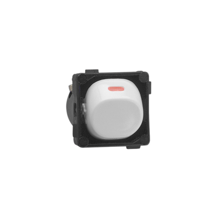
A hallway light switch that's gone stiff, sparky, or stopped clicking properly isn't always a job for a whole new plate — nine times out of ten it's just the mechanism underneath that's died, and the plate on the wall is perfectly fine to keep. The tricky part isn't the swap itself. It's working out which replacement mechanism actually fits the plate that's already screwed into the wall.
Before pulling a mechanism out, it's worth ruling out the obvious impostor. A switch that buzzes, flickers the light, or only half-works on dimmer circuits often gets blamed on the switch mechanism when the real fault is an incompatible dimmer controller — worth a quick check against picking the right controller for flickering LED dimmers before you assume the mechanism itself is the problem. If the switch is a straight on/off (not a dimmer) and it's gone loose in the toggle, doesn't click positively, or has visibly darkened/melted terminals, that's a genuine mechanism failure and it's time to replace it.
[!] Before you isolate anything: switching out a light switch mechanism is fixed wiring work. In most Australian states this needs to be done, or at minimum signed off, by a licensed electrician — it's not a DIY job for an unlicensed homeowner, regardless of how simple the swap looks.
This is where most replacement jobs go sideways. Switch mechs aren't universal — each plate series is built around a specific mechanism footprint, and mixing brands is hit and miss even when the mechanism looks close enough by eye. A Clipsal 30 Series plate takes a Clipsal 30 Series mechanism (snap-in, rectangular base). Legrand runs three separate plate families — Como, Excel and Vivo — and a mechanism from one doesn't drop into another despite looking superficially similar. HPM's 770 module system uses its own mounting pattern entirely, and Hager's Allure and Rotoloc ranges are their own thing again.
| Plate Series | What to Look For | Compatible Mechanism |
|---|---|---|
| Clipsal 30 Series | Rectangular snap-in mechanism, moulded plastic clips on the back | Clipsal 30 Series mechanisms only |
| Legrand Como / Excel / Vivo | Check which of the three families is stamped or moulded on the mechanism back — they're not interchangeable with each other | Same family only (Como to Como, Excel to Excel, Vivo to Vivo) |
| HPM 770 module | Wide, flat rocker module design distinct from Clipsal/Legrand mechanisms | HPM 770 series modules only |
| Hager Allure / Rotoloc | Flush-mount mechanism with Hager's own clip system | Hager Allure/Rotoloc mechanisms only |
If there's no visible brand marking on the old mechanism, the plate itself is usually the giveaway — check the fixing screw spacing and the shape of the mounting lugs, since these are what actually determine fit, not just brand name recognition.
Related Reading
Once the right mechanism is confirmed, the swap itself is straightforward. Isolate the circuit at the switchboard and confirm dead with a voltage tester before touching anything — don't rely on the light being off as proof the circuit is de-energised. Remove the two fixing screws holding the plate to the wall box, gently ease the mechanism out, and take a photo of the terminal wiring before disturbing it. Most single-gang switches only have two or three conductors (active in, active out, sometimes a loop for 2-way circuits), but getting them mixed up on reassembly is the single most common mistake on this job. Loosen the terminal screws, transfer each conductor to the matching terminal on the new mechanism, and torque the screws down firmly — a loose terminal here is what causes the buzzing and heat damage that brings people back to this job a second time.
Screw the new mechanism back into the existing plate, check it seats flush without gaps, then restore power and test before closing everything up. If the switch turns out to be part of a multi-point circuit rather than a straightforward single-pole setup, the wiring at the terminals will look different from what's described above and needs its own approach.
Buying by plate colour instead of mechanism series. A white Clipsal plate and a white Legrand plate look nearly identical on the wall, but the mechanisms behind them aren't interchangeable — colour tells you nothing about fit.
Assuming a higher amp rating always fits. A 16A mechanism isn't automatically a drop-in replacement for a 10A one from the same brand — physical footprint can differ between rating tiers within the same series.
Not checking the pole count before buying. A single-pole mechanism and a 2-way mechanism can look almost identical from the front, but wiring them into the wrong circuit either won't work or will leave a terminal live when it shouldn't be.
Skipping the terminal torque check. A mechanism that's mechanically fine but loosely terminated will run warm, discolour the terminal housing, and eventually fail again within months — it's a common callback cause.
Reusing a damaged plate on a new mechanism. If the old plate's mounting lugs are cracked or the fixing screw holes have stripped out, the new mechanism won't seat properly no matter how good the mechanism itself is.
Can I replace just the switch mechanism without buying a new plate?
Yes, in most cases — as long as the plate itself isn't cracked or damaged and you buy a mechanism from the same series, for example a 10A Clipsal 30 Series mechanism for an existing Clipsal 30 Series plate.
Why does a new switch mechanism feel stiffer than the old one?
Brand new mechanisms typically have a firmer, more positive click than a switch that's been operated thousands of times — this usually settles in within the first few weeks of normal use and isn't a fault.
Can I mix brands, like putting a Legrand mechanism into a Clipsal 30 Series plate?
Not reliably. The mounting lugs, fixing screw spacing and mechanism footprint differ enough between brands that a cross-brand fit is generally not possible, even when the mechanisms look visually similar.
What mechanism fits an HPM 770 module plate?
HPM 770 module plates need a mechanism from the same 770 range, such as the HPM 770 series rocker switch mechanism — the module footprint doesn't match Clipsal or Legrand mounting systems.
Do I need a licensed electrician to replace a switch mechanism in NSW?
Yes. Replacing a switch mechanism involves working on fixed wiring, which in NSW and most other Australian states requires the work to be carried out or supervised by a licensed electrician — it's not classed as a general DIY task.
Is a 2-way switch mechanism the same as an intermediate switch?
No — a 2-way mechanism like this Connected Switchgear slimline unit controls a light from two points, while an intermediate switch sits between two 2-way switches to add a third (or more) control point — they're wired differently and aren't interchangeable in a circuit.
Related Reading
Trade pricing on switch mechs across all the major plate series, dispatched same day from Kingsgrove NSW.
Find the full switch replacement mechanism range at Schnap — trade pricing and same-day dispatch from Kingsgrove NSW.

A hallway with switches at both ends and a landing halfway between them should let anyone kill the light from any of the three points. Plenty of sparkies get a callback anyway, usually because the middle switch does something odd -- the light comes on but won't turn off, or one end stops working altogether. Nine times out of ten it's an intermediate switch wired as if it were just another 2-way, with the crossover terminals never actually crossed -- and that's the wiring logic this guide walks through.
Take that hallway job, or the more common version for trade work -- a garage with doors at both ends that both need to control the same overhead light. The live feed lands on the first switch, which is a 2-way switch, not a standard single-pole. Instead of switching the light directly, it switches between two traveller conductors running to the next point. Those travellers land on the intermediate switch in the middle, which either passes them straight through or crosses them over depending on its position. From there, a second set of travellers runs to the final 2-way switch, which switches the light itself. Any single switch flipping breaks or completes the circuit, which is why all three points can independently turn the light on or off.
| Position in Circuit | Switch Type Needed | Typical Terminal Count |
|---|---|---|
| First and last point (2 total) | 2-way switch | 3 (in practice, typically COM, L1, L2) |
| Every middle point | Intermediate switch | 4 (in practice, typically L1, L2, L3, L4) |
| Simple single-point switching | 1-way (single pole) switch | 2 (in, out) |
This is where most of the callbacks actually come from. An intermediate switch mechanism needs four traveller conductors landed on it, not two -- one pair in from the previous switch, one pair out to the next. Swap a standard 2-way switch mechs into that middle position by mistake, or land the travellers on the wrong terminal pair, and the light either won't switch off from the middle point or won't switch at all once every switch is flipped an odd number of times. Search "clipsal iconic intermediate switch wiring diagram" and you'll find dozens of near-identical layouts online -- the crossover logic inside the mechanism is the same underlying principle regardless of which range or brand of switch mechs you're actually installing, so don't assume the wiring changes just because the product line does.
Once the switch end is sorted, don't assume the fixture end looks after itself. If the circuit terminates at a pendant fitting rather than a batten holder, wiring a pendant socket outlet correctly there matters just as much -- the neutral and earth connections at that end are just as easy to get backwards as the travellers are at the switch end, and a fault there will look identical to a switch wiring fault from the customer's side.
For the two end points -- the top and bottom of a staircase, or either end of a corridor -- a 2-way switch does the job on its own. For every point in between, it has to be an intermediate switch, no exceptions; a 1-way switch dropped into a middle position simply won't pass the travellers through. If the space is a detached garage or workshop with fuel or chemical storage nearby, check whether the location falls under hazardous-area classification -- a Zone 1 rated intermediate wiring point calls for a hazardous-area rated 2-way switch rather than a standard domestic mechanism, and that's a separate product line worth confirming with your supplier before you order.
Wiring the middle switch like a 2-way. Only two travellers get landed instead of four, so the light can't be killed cleanly from that point -- this is the single most common cause of the "won't turn off" callback described above.
Mixing switch mechs from different ranges without checking terminal layout. Not every brand labels its traveller terminals the same way, and assuming one diagram applies to every mechanism on the job leads to crossed wiring.
Using a single-pole switch at a middle point. It physically fits the same plate, so it's an easy mix-up on-site, but it has no pass-through terminals at all.
Skipping the continuity test before closing up the plate. A crossed traveller is invisible once the plate is screwed back on, and fault-finding it later means opening up every switch in the run again.
Overlooking the hazardous-area requirement in garages and workshops. A standard mechanism installed where a Zone-rated one was required is a compliance issue that won't show up until an inspection.
Not isolating power before starting. Basic, but still the most common reason these jobs go wrong in the first ten minutes rather than at the wiring stage.
Do I need an intermediate switch for a 3-way light circuit?
Yes, if you want the light controlled from three or more points. Two 2-way switches on their own only give you two control points; every point beyond that needs an intermediate switch mechanism wired into the traveller run.
What's the difference between a 2 way switch and an intermediate switch?
A 2-way switch has three terminals and directly switches which traveller carries the live feed. An intermediate switch has four terminals and doesn't switch the light itself -- it either passes the travellers straight through or crosses them, which is what lets you add extra control points in the middle of a run.
Can I control a light from four different switches?
Yes -- use a 2-way switch at each end and an intermediate switch at each of the two middle points, wired in series between the end switches with travellers.
Is a licensed electrician required to wire an intermediate switch in NSW?
Yes. This is fixed wiring work covered under AS/NZS 3000, and it needs to be carried out or signed off by a licensed electrician regardless of how straightforward the job looks.
Why does my hallway light only turn off from one switch?
In practice, this is almost always a middle switch wired as a 2-way instead of an intermediate, or travellers landed on the wrong terminal pair. Isolate the circuit and check the middle switch's terminal count against what's actually landed on it before assuming the fault is elsewhere.
What amp rating switch mechanism should I use for a 3 point lighting circuit?
For a standard domestic lighting load, a 10A mechanism is typically sufficient, though a 15A rated switch mechanism gives extra headroom on heavier or combined lighting loads.
Related Reading
Trade pricing across the full switch mechs range, dispatched same day from Kingsgrove NSW.
See the full intermediate switch wiring range at Schnap and get same-day dispatch from Kingsgrove NSW.
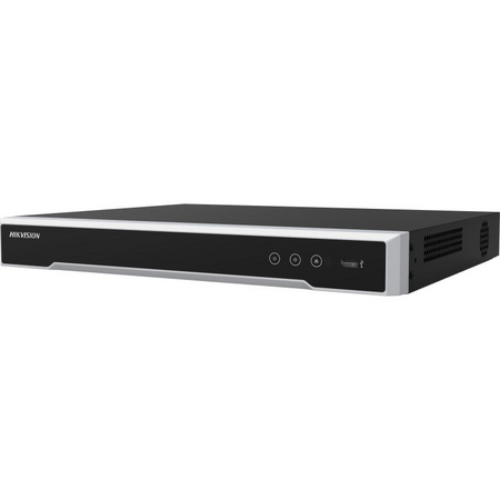
A client asks for eight cameras across a warehouse and office fit-out, the quote gets locked in on an 8-channel NVR, and six months later they want two more cameras over the loading dock. Now there's no channel left, no spare PoE port, and a return visit that could have been avoided at the quoting stage. Before locking in a channel count, it's worth picking NVR over DVR for the right reasons, because that decision changes how much headroom actually matters.
The channel count on the box is the ceiling, not the plan. Walking a site and counting entry points, internal corridors, stock areas and the odd spot the client mentions "eventually" is a different exercise to counting what's on the initial scope sheet. An 8-camera job that gets sized to an 8-channel NVR has zero room -- not for a camera that fails and gets swapped for a different model, not for a client request three months in, nothing. Sizing to the exact number on the quote treats that number as fixed, when in practice it rarely stays that way once the client sees the system running.
A more reliable approach is to count confirmed cameras first, then ask the client a direct question: are there any areas they've thought about covering but haven't committed to yet? That answer usually adds one or two cameras to the real number, even if it doesn't change what gets installed on day one.
It's a common assumption that an "8-channel NVR" means 8 cameras plug straight in and that's the end of the sizing conversation. In practice, channel count and PoE port count are two separate specs that happen to match on a lot of models -- but not all of them. Some NVRs are sold with fewer built-in PoE ports than channels, on the assumption that extra cameras will be powered through a separate PoE switch or existing network infrastructure. If a job is being priced on the NVR's ports alone, it's worth checking the actual port count against the channel count on the datasheet before quoting, rather than assuming they line up.
[!] PoE Budget Note: Even when the port count matches the channel count, total PoE wattage across all ports is typically capped at a combined budget, not per-port maximum. Higher-draw cameras (PTZ units, cameras with heaters, or long-range IR) can, in practice, eat into that shared budget faster than a straightforward count of ports would suggest -- it's worth checking the NVR's total PoE budget against camera power draw on larger jobs, rather than assuming every port can run at full load simultaneously.
Sizing to exactly what's on the quote is the single biggest reason installers end up doing a return visit for a system upgrade instead of a simple camera add. A 12-camera site sized to a 12-channel NVR has no path forward -- the next camera means a new recorder, a data migration, and a client asking why the original system couldn't handle "just one more camera." Sizing one tier up from the confirmed count is generally the more defensible call, even if it costs slightly more at quoting stage, because it turns a future system replacement into a five-minute cable-in.
This matters more on commercial jobs than residential ones. A homeowner with six cameras rarely adds more. A warehouse, retail fit-out, or multi-tenant commercial site is a different story -- cameras tend to get added as the business grows, as incidents happen, or as insurance requirements change. Sizing commercial jobs with headroom in mind from the start avoids the awkward conversation where the client assumes "adding a camera" is a small job and finds out it's actually a full recorder swap.
Related Reading
As a general starting point, the table below maps typical job types to a channel count, based on confirmed camera count plus reasonable headroom -- not a hard rule, but a useful sense check against what's being quoted.
| Typical Job | Confirmed Cameras | Suggested NVR Size |
|---|---|---|
| Small shop or office | 2-4 | 4-channel |
| Warehouse or mid-size retail | 6-10 | 8 to 16-channel |
| Multi-building or larger commercial site | 14-24 | 32-channel |
| Large facility, campus, or multi-tenant complex | 40-60+ | 64 to 128-channel |
For genuinely large-scale deployments -- multi-site enterprise, large campus, or centralised monitoring across several buildings -- 256-channel recorders exist for exactly that scenario, though a job that size is generally the exception rather than the norm on most installer schedules.
Quoting to the exact camera count with zero spare channels. This is the mistake behind almost every "can we just add one more camera" callback -- there's no slack built in, so any change means a new recorder.
Assuming PoE ports always match channel count. As covered above, some models separate the two -- checking the datasheet avoids a job where the recorder arrives short on ports.
Ignoring total PoE wattage budget on larger camera counts. A recorder with enough ports can still run short on power if several high-draw cameras (PTZ, heated housings) are on the same system.
Sizing storage as an afterthought. Channel count decides how many cameras can connect, but drive capacity decides how long footage is actually retained -- a correctly sized channel count with an undersized drive still leaves the client with gaps in their recording history.
Not asking about future stages. Client mentions a warehouse expansion or a second building coming online in a year, and the recorder gets sized to the current stage only -- a five-minute conversation at quoting stage avoids this.
Treating small residential and commercial jobs the same way. A 4-channel recorder that's right for a small shop is the wrong call for a warehouse that's likely to grow -- job type matters as much as current camera count.
can I use a 16-channel NVR with only 8 cameras right now?
Yes -- an NVR doesn't need every channel populated to work correctly. Running 8 cameras on a 16-channel unit simply leaves 8 channels free for later, which is generally a reasonable way to build in headroom on a job expected to grow.
how many channels do I need for a 12-camera site?
Based on the confirmed count alone, a 16-channel unit covers it with a small buffer. If the client has mentioned any expansion plans, a 16-channel NVR with 16 PoE ports gives room to grow without a recorder swap down the track.
do I need to be a registered cabler to run PoE cabling for a CCTV system in NSW?
Structured cabling work connecting to a network -- including PoE runs for CCTV -- typically falls under cabling registration requirements administered through the ACMA framework, and licensing rules can vary depending on the specific scope of work. It's worth confirming current registration requirements for the job at hand before starting cabling work, rather than assuming it falls outside scope.
why does my 8-port NVR only power 4 cameras properly?
This usually comes back to the total PoE wattage budget being shared across all ports rather than allocated per port -- if the connected cameras draw more combined power than the unit supports, some ports may underperform even though they're technically active. Checking the datasheet's total PoE budget against actual camera draw before commissioning avoids this. For jobs with several higher-draw cameras, an 8-channel NVR with a higher PoE port budget is worth checking against the load.
how much hard drive space do I need for 8 cameras recording continuously?
This depends heavily on resolution, frame rate, and compression, so there's no single figure that applies to every job -- as a general rule, higher-resolution cameras recording continuously (rather than motion-triggered) will fill storage noticeably faster than a lower-resolution, motion-triggered setup. Checking the manufacturer's storage calculator against the specific camera models on the job is more reliable than estimating.
can I add more cameras to my NVR later without swapping it out?
Only if there's spare channel capacity and PoE headroom already built in -- this is the core reason for sizing above the exact confirmed camera count in the first place. On jobs likely to grow, a 32-channel NVR leaves considerably more room than sizing tight to the current count.
For the full range of NVR CCTV recorders in other channel counts and configurations, see the shop section below.
Trade pricing and same-day dispatch from Kingsgrove NSW across the full NVR range, from small-site 4-channel units through to enterprise-scale 256-channel recorders.
See the full NVR channel count range at Schnap and get same-day dispatch from Kingsgrove NSW.
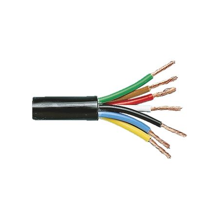
A box trailer rolls into the shop for a full rewire — tail lights, stop lights, both indicators, reverse lights, and a rear fog light, six functions in total. Cable gauge is the easy part; the harder question is how many cores actually get every one of those functions back to the plug without doubling two circuits onto one wire. That decision point — core count matched to function count — is where trailer wiring jobs go sideways before the crimping even starts.
A standard AU 7-pin trailer plug is commonly wired for seven functions: earth, tail/park lights, stop lights, left indicator, right indicator, reverse lights, and an auxiliary circuit for fog lights or a charge line. In practice, not every trailer needs all seven wired separately — the core count you actually need comes down to how many of those functions the trailer carries, not the cable's rated amperage.
A simple single-axle box trailer with tail, stop, and shared indicator lights typically gets by on 4 cores. Add separate left and right indicators and you're usually looking at 5 cores. It's only once reverse lights and a fog or aux light both come into the build — the case with the trailer above — that a genuine 7-core run earns its keep, because each of those functions needs its own dedicated conductor back to the plug rather than sharing a wire with something else.
| Core Count | Typical Function Coverage | Common Use Case |
|---|---|---|
| 2-core | Single circuit plus return | Short extension runs or a single dedicated accessory circuit |
| 4-core | Earth, tail/park, stop, shared indicator | Basic single-axle trailers without reverse or fog lights |
| 5-core | Earth, tail/park, stop, separate LH/RH indicators | Trailers needing independent indicator circuits, no reverse/fog |
| 7-core | Earth, tail/park, stop, LH/RH indicators, reverse, fog/aux | Full-function tandem or box trailers with reverse and fog lights |
Related Reading
Getting the core count right only solves half the problem — each stranded core still has to land on a pin or terminal without the strands splaying, working loose, or wicking moisture up the conductor. Trailer plugs and junction boards typically use screw or spring-clip terminals, and bare stranded ends pushed straight into either one tend to loosen over time as the trailer flexes on rough tracks or boat ramps.
Ferruling each core before it goes into the plug or junction board gives it a solid, uniform end that seats properly and resists corrosion better than a bare crimped or twisted strand bundle — matching ferrule size to trailer cable cores is worth checking against the core's actual cross-sectional area rather than guessing off the cable's overall diameter. On an oil-resistant 7-core run destined for a boat trailer or a farm trailer that sees grease and diesel, that terminal quality matters more than usual — a loose reverse light connection is annoying, but a loose earth core is the one that tends to cause the most confusing intermittent faults.
Doubling two functions onto one core to save a wire. Sharing a core between the stop light and one indicator to avoid stepping up from 5-core to 7-core usually means the brake light flashes along with the indicator, or the indicator dims when the brakes are also on — an easy fault to chase for hours before realizing it was a wiring shortcut, not a bulb or relay issue.
Skipping ferrules on stranded cores. Pushing bare stranded ends straight into spring-clip plug pins often works fine on the bench, then loosens after a few thousand kilometres of trailer vibration and road grime working into the joint.
Choosing core count by price instead of function count. A cheaper 4-core cable looks like the better buy until reverse lights or a fog light get added later and the whole loom has to be re-pulled through the chassis — running the 7-core from the start is usually the cheaper option over the trailer's life.
Assuming the chassis handles earth return. Some older trailers rely on a chassis or coupling earth return rather than a dedicated core, but corrosion at the coupling or axle stub can make that return unreliable — running a dedicated earth core in the multicore cable is generally the more predictable approach for a full rewire.
Not labelling cores at both ends during the pull. On a 7-core run, sorting seven similarly coloured conductors at the plug end without labels usually means testing each one individually with a multimeter — a step that's quick to skip when pulling the cable, and slow to redo once it's already run through the chassis.
does a trailer with reverse lights need 7 cores or can I get away with 5?
If reverse lights are wired as their own circuit rather than shared with another function, they typically need a dedicated core — on a trailer that also has separate LH/RH indicators, that generally pushes the count from 5 to 6 or 7 depending on whether a fog/aux circuit is fitted as well.
what's the actual difference between 4-core and 5-core trailer wire?
The step from 4-core to 5-core is usually one extra dedicated conductor, most often used to split a shared LH/RH indicator circuit into two independent ones. See the 3-core FLRYY cable for jobs that sit between the two.
can I run fog lights and reverse lights off the same core?
Combining them on one core generally means both circuits switch together, which isn't correct for either function — reverse lights should only activate in reverse gear and fog lights are typically switched independently, so in practice each one needs its own dedicated core.
do I need a licensed auto electrician to wire a trailer plug in Australia?
Requirements vary by state and by whether the trailer is used commercially, so it's worth checking current licensing rules for your state before starting a trailer light rewire — this isn't something to assume is DIY-only just because it's low voltage.
can I use bootlace ferrules on FLRYY trailer wire?
Yes — FLRYY cores are fine-stranded, which is exactly the type of conductor ferrules are designed for. Sizing them correctly matters more than the ferrule brand; see the twin bootlace ferrule option if two cores are landing on a single terminal.
why does my trailer wiring keep corroding at the plug?
Bare stranded ends left uncrimped are more prone to wicking moisture up the conductor, especially on trailers regularly exposed to boat ramps or wash-down. An oil-resistant jacket helps with the outer sheath, but the termination itself is usually where corrosion actually starts.
Related Reading
Schnap stocks the FLRYY range across trade pricing with same-day dispatch from Kingsgrove NSW, from single-circuit 2-core through to full 7-core trailer looms.
Browse the full automotive and vehicle cable range at Schnap for trade pricing, trusted brands, and same-day dispatch from Kingsgrove NSW.
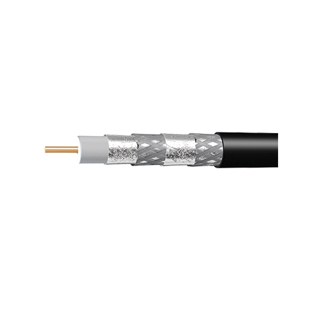
A 40-metre run of RG6 out to a rear shed, split three ways to feed extra TV points, and the picture on the furthest set starts breaking up whenever it rains. It's a familiar callback for anyone doing antenna, satellite, or CCTV work around Australian properties — and the fix isn't always "run new cable everywhere." Sometimes RG6 is still fine. Sometimes the run genuinely needs RG11. Here's how to tell the difference before you order the wrong cable.
In practice, every coax cable loses a small amount of signal per metre it runs — this is called attenuation, and it's typically worse at the higher frequencies used by satellite and some digital TV signals. A splitter adds loss of its own on top of that, generally a few dB per split as a rough rule of thumb, which is why a 3-way splitter on an already-long run compounds the problem fast. RG6 handles short-to-moderate runs comfortably. Once you stack enough distance and enough splits together, though, the accumulated loss can drop the signal below what the tuner or set-top box needs to hold a clean lock.
This is the part that catches people out: it's rarely one single factor. A 25-metre run with no splits might be perfectly fine on RG6. The same 25 metres feeding a 4-way splitter to multiple rooms is a different story entirely.
The core difference comes down to conductor and jacket size, and what that does to signal loss over distance:
| Spec | RG6 | RG11 |
|---|---|---|
| Typical outer diameter | Around 6.9mm | Around 10.3mm |
| Centre conductor | Copper-clad steel, roughly 1mm | Copper-clad steel, roughly 1.6mm |
| Signal loss over distance | Higher loss per metre | Lower loss per metre — in practice, roughly half the attenuation of RG6 at the same frequency |
| Flexibility | Easier to route, tighter bends | Stiffer, needs a wider bend radius |
| Typical use | Standard antenna and in-wall runs, most residential jobs | Long runs, heavy splitting, distribution amps, MDU/commercial |
Most standard antenna jobs — a single run from roof to lounge room, or a couple of splits inside a normal-sized house — sit comfortably within what RG6 is built for. It's easier to route through wall cavities and around tight corners, which matters more than people expect once you're fishing cable through an existing ceiling space. If the run is under roughly 30 metres with no more than a couple of splits, RG6 is generally the more practical choice, not just the cheaper one.
[!] Compliance note: For fixed antenna and pay-TV installations, coax cable is generally expected to carry AS/ACIF S008/S009 compliance marking. It's worth checking this on the cable jacket before committing to a bulk order, particularly for commercial or multi-dwelling jobs.
Once a run starts pushing past 30-40 metres, or you're feeding a 3-way or 4-way splitter over any real distance, the accumulated loss from cable and splitters together can genuinely put you below a usable signal level — especially on the furthest outlet. That's the point where swapping to RG11 for the main trunk run (even if the shorter branch runs off the splitter stay on RG6) tends to solve the problem properly, instead of chasing it with an amplifier that just adds noise along with signal.
Once you've decided RG11 is the right call, how you terminate it matters just as much as the cable spec — a compression connector rated for the thicker RG11 jacket, fitted properly, is what actually stops the signal loss argument from becoming a moot point. If you're not sure whether to go compression or crimp for the termination, our guide on terminating coax with F-type connectors walks through it, including how to keep water out of a rooftop or eave termination.
Related Reading
Judging the run on distance alone. A 20-metre run with a 4-way splitter can lose more signal than a 35-metre run with no splits at all. Add up distance and splitter loss together before deciding.
Mixing RG6 and RG11 without matching the connectors. RG11's thicker jacket needs its own compression connector — an RG6-rated connector won't seat properly on RG11, and forcing it usually means a poor crimp that fails months later.
Upgrading the trunk but forgetting the splitter rating. A cheap splitter can undo the benefit of the upgrade — check it's rated for the frequency range you're working with, particularly on satellite jobs.
Going RG11 "just in case" on a short indoor run. The stiffer cable is genuinely harder to route through tight wall cavities and ceiling penetrations, for no real signal benefit on a run that was never going to struggle.
Not checking the existing wall plate or outlet. Some older outlets and F-type wall sockets aren't built for the extra bulk of RG11 — worth a quick check before the whole trunk gets upgraded.
Can I mix RG6 and RG11 on the same run?
Yes, this is common practice — RG11 on the long trunk run where loss adds up, then RG6 on the shorter branch runs off a splitter closer to each outlet. Just make sure the connectors are matched to each cable type at the transition point.
How much further can RG11 actually run before signal drops?
As a general rule, RG11 can typically push noticeably further than RG6 before hitting the same signal loss, though the exact distance depends on frequency, splitter count, and cable quality. For long or heavily split runs, going with a quad shield RG11 cable gives you the most margin.
Do I need a licence to run antenna coax in NSW?
Antenna and satellite installation work in Australia typically falls under separate registration requirements to general electrical licensing — it's worth confirming current requirements with the relevant state regulator before taking on antenna or satellite work, particularly for commercial jobs.
What connector do I actually need for RG11 versus RG6?
RG11 needs a connector sized for its thicker jacket and larger centre conductor — an RG6-rated connector won't compress properly onto it. A compression tool rated for RG6 through RG11 covers both without needing separate tools.
For the full range of RG6, RG11, and other coaxial TV cable, see the shop section below.
Trade pricing on both cable types, with same-day dispatch from Kingsgrove NSW on stocked lines.
Find the full RG6 vs RG11 range at Schnap — trade pricing and same-day dispatch from Kingsgrove NSW.
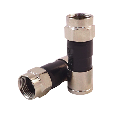
A rooftop antenna install works fine for three weeks, then the first proper rain hits and the picture starts breaking up. Nine times out of ten, the cable itself is fine -- it's the F type connector on the end of it that let water in.
RG6 is a well-shielded cable on its own. Where things go wrong is at the termination point, particularly on runs that end up exposed -- a lead-in to a roof-mounted antenna, a run along an eave to a satellite dish, or a CCTV camera feed clipped along an outdoor wall. A crimp connector barrel that isn't fully seated, or a compression connector tightened without checking the seal, leaves a gap small enough to miss on install day but large enough for moisture to track in over a few wet seasons. Once water gets past the connector and into the braid, corrosion sets in slowly -- signal loss shows up gradually rather than all at once, which is part of why it's easy to blame the cable run instead.
If you haven't locked in the cable itself yet, worth sorting that first -- picking between RG6 and RG11 cable changes what connector barrel size you'll need at termination.
Both methods terminate the same cable end, but the mechanism -- and what it means for a weatherproof result -- is different.
| Method | How it seals | Best suited to |
|---|---|---|
| Crimp | Barrel is mechanically crimped onto the braid with a dedicated tool; no compression ring or O-ring | Indoor runs, wall plates, patch points not exposed to weather |
| Compression | Ring is compressed over the connector body, typically with an O-ring seal against the fitting | Outdoor, rooftop, or any run where the termination sits exposed to rain or humidity |
In practice, a crimp connector can be perfectly reliable indoors -- it's a faster termination and there's no seal to worry about because there's nothing to seal against. The problem only shows up when a crimp-terminated cable ends up outside, which happens more often than it should when the same box of connectors gets used for every job regardless of where the run terminates.
[!] For any termination that ends up exposed to weather -- rooftop, eave, external wall -- a weatherproof compression connector with dual O-ring seals is the safer default, even if the run looks sheltered on install day.
The termination itself follows the same basic steps whether it's crimp or compression -- strip the outer jacket to expose the braid, fold the braid back over the dielectric, trim the centre conductor to length, then fit the connector. Where it goes wrong on outdoor jobs is usually at the strip stage: too much jacket removed leaves braid exposed beyond the connector body, and that gap becomes the entry point for moisture even with a compression seal fitted correctly. A stripping tool set to the right cable diameter keeps that cut consistent, rather than eyeballing it with a utility knife.
For rooftop antenna work specifically, Foxtel-approved compression connectors are worth using even on non-Foxtel installs -- the approval reflects a tighter tolerance on the compression fit, which matters more outdoors than the brand name does. Once the connector's on, a quick tug test and a visual check that the O-ring seal sits flush (not pinched or twisted) takes a few seconds and catches most of the failures that would otherwise show up as static after the next storm.
Using crimp connectors on an outdoor run because that's what was in the toolbox. It's the single biggest cause of the "worked fine until it rained" callback -- crimp connectors aren't designed to seal, and swapping them out later means re-terminating the whole run.
Over-stripping the cable jacket. Leaving braid exposed past the connector body defeats the seal even on a correctly compressed connector -- the water ingress point moves rather than disappears.
Skipping the F male size check on Foxtel work. Not every compression connector marketed for RG6 is Foxtel-approved -- using an unapproved connector on a Foxtel install can mean a failed inspection even if the termination itself is sound.
Reusing a connector after a failed compression attempt. Once a compression ring's been crimped once, the O-ring seal is often already compromised -- re-crimping the same connector body rarely restores a reliable seal.
Mixing RG6 and RG59 connectors. The two cables have different outer diameters, and a connector sized for one won't seat properly on the other -- it might go on, but the compression or crimp won't sit right against the dielectric.
do I need a compression connector for an indoor coax run or is crimp fine?
Crimp is fine for indoor runs that won't be exposed to moisture -- wall plates, patch panels, internal distribution points. Compression is really an outdoor-run requirement rather than a universal upgrade.
what's the difference between the RG6 F male compression connector and the standard one?
The main practical difference on jobs where it matters is Foxtel approval -- a tighter compression tolerance that's specified for Foxtel installs but works fine as a general higher-spec option for any outdoor run, like this Foxtel-approved F male compression connector.
can I use the same compression tool for RG59 and RG6?
Only if the tool has an adjustable spin knob rated for both diameters -- fixed-size compression tools are built for one cable size and won't seat the other correctly. An adjustable compression tool covering RG59 through RG11 avoids needing separate tools for each cable size.
why does my crimped F connector keep coming loose after a few weeks?
Usually a crimp that wasn't fully seated at the barrel, or a stripping cut that removed too little jacket so the connector body isn't gripping the braid properly. Checking the strip length against the connector spec before crimping typically resolves it.
do I need to be a registered cabler to terminate coax for a TV antenna install in Australia?
Antenna and pay-TV cabling generally falls under ACMA's cabling registration rules, and most rooftop antenna and outdoor coax work needs a registered cabler to carry it out -- worth checking current ACMA cabling provider rules for the specific job type before quoting.
is a weatherproof connector actually necessary if the cable run is under an eave?
An eave reduces direct rain exposure but doesn't eliminate humidity and wind-driven moisture -- in practice, most installers still use a weatherproof compression connector for anything outside the wall cavity, eave-covered or not.
Related Reading
Trade pricing and same-day dispatch from Kingsgrove NSW on compression and crimp connectors for coaxial tv cable termination, plus the tools to fit them properly.
Find the full f type connector range at Schnap -- trade pricing and same-day dispatch from Kingsgrove NSW.
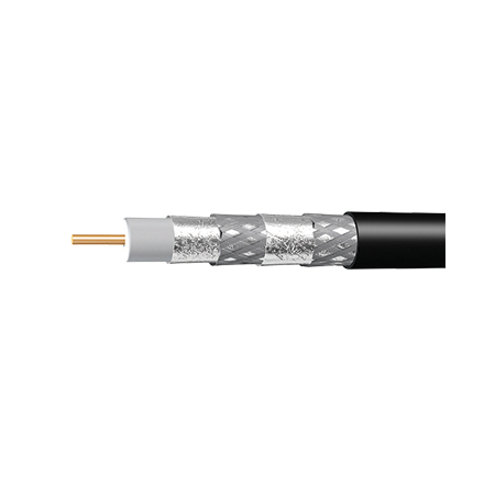
You've just mounted a new UHF antenna on the roof, and the client also wants a CCTV camera covering the driveway from a shed 15 metres away. The spare roll of RG6 sitting in the van handles the inside runs fine — but the moment that cable has to survive full sun along the eave, then go underground beneath a path, "whatever's in the van" stops being good enough.
Standard PVC-jacketed RG6 is built for indoor runs and short, protected outdoor stretches — a wall penetration into a roof cavity, for example. It's not designed for prolonged UV exposure, and it's definitely not rated to sit in contact with damp soil. Left exposed on a north-facing wall for a couple of years, the jacket can crack; buried without protection, moisture eventually tracks along the braid and shows up as signal dropout or corrosion at the connector months later — long after the installer has left site.
The fix isn't always a different cable altogether. Schnap stocks RG6 and RG11 in several jacket variants built for exactly this situation, and picking the right one comes down to what the cable is actually doing at each point of the run — aerial, wall-mounted, or buried.
Back to the roof job: the antenna mast sits a metre or so proud of the eave, and there's a short unsupported span before the cable reaches the fascia. Run standard cable across that gap and its own weight, plus wind load over time, puts constant strain on the F-connector at the mast end — that's a common cause of intermittent signal loss that only shows up in bad weather.
Messengered coax solves this with a steel support wire bonded along the jacket, so the cable carries its own weight across the span instead of relying on the connector. It's the right call for any aerial run — dish drops, antenna masts, or a cable running unsupported between a house and a detached structure — where the cable isn't sitting in conduit or clipped continuously.
Once the cable comes off that aerial span and heads into a wall-mounted run down to floor level, in practice a properly clipped standard or messengered cable in conduit is usually fine for the vertical section — the messenger wire isn't doing anything useful once the cable is fully supported.
The last four metres of the shed run is where most installers get caught out. Once the cable goes under a path or garden bed — even inside conduit — it's sitting in a damp environment for years, and a compromised jacket or a nick from the install itself becomes a slow leak point for moisture.
Flooded RG6 and RG11 are gel-filled between the jacket and the shield, so even if water finds a way in at a joint or a damaged section, it can't track along the cable to the connector. This is the variant to reach for any time the run goes into the ground, into a wet subfloor, or anywhere it'll sit in standing water — conduit or no conduit.
[!] Don't rely on conduit alone. Conduit protects the cable mechanically, but it's not watertight over the long term — condensation and groundwater can still find their way in through joints and end caps. For any buried run, flooded cable is the layer that actually stops water reaching the copper.
| Variant | Best for | Not for |
|---|---|---|
| Standard PVC RG6 | Indoor runs, short protected outdoor sections in conduit | Aerial spans, burial, prolonged UV |
| Messengered RG6/RG11 | Unsupported aerial spans — antenna, dish, house-to-shed drops | Buried or fully clipped/conduited sections |
| Flooded RG6/RG11 | Direct burial, wet subfloors, standing water exposure | Aerial spans needing self-support |
Getting the right cable variant sorted only solves half the problem — the other common failure point outdoors is the connector itself. Standard indoor F-connectors aren't sealed against moisture, and once one corrodes at an outdoor termination point, it doesn't matter how good the cable behind it is. Weatherproof compression connectors with dual O-ring seals are worth using at every outdoor termination, and it's worth reading up on choosing weatherproof F-type connectors if you're not already using compression rather than crimp fittings on outdoor jobs.
Running standard cable underground because "it's in conduit anyway." Conduit slows water ingress, it doesn't stop it — over a couple of wet seasons, moisture usually finds a way to the jacket regardless.
Letting cable sag across an aerial span. Without a messenger wire, the load ends up on the F-connector at each end, and that's typically where the first fault shows up after a storm.
Using indoor crimp connectors outside. They're cheaper and faster on the day, but they're not sealed — corrosion at the pin is one of the most common causes of a "working fine, then suddenly not" outdoor coax fault.
Choosing cable based on price per metre alone. Flooded cable costs more than standard PVC, but a callback to dig up and replace a failed buried run costs a lot more than the price difference ever would.
Ignoring run length on long shed or outbuilding drops. Past roughly 30 metres, signal loss in RG6 starts to add up — RG11's thicker centre conductor and lower loss per metre is usually the better call for those longer runs.
Is standard RG6 ok to run along an outside wall?
In practice, yes for a short, clipped or conduited vertical run in a spot with reasonable weather protection — the issue is longer-term UV exposure and any section that ends up in contact with the ground, not a wall run on its own.
What's the difference between messengered and flooded coax?
Messengered cable has a steel support wire for unsupported aerial spans; flooded cable has gel filling to stop moisture tracking through the cable when it's buried or sitting in wet conditions. They solve different problems, and a single run can sometimes need both variants at different points.
Can I use RG6 for a 20 metre run to a shed or do I need RG11?
RG6 is generally fine at that distance for antenna and CCTV feeds. Past around 30 metres, or for anything low-loss sensitive, an RG11 messengered cable is worth the switch.
Do I need a licence to install antenna coax outside in Australia?
As a general rule, standard residential antenna and CCTV coax work doesn't require ACMA cabling registration the way telecommunications cabling to the network boundary point does. Requirements can vary by job type and connection point, so it's worth checking the current ACMA Cabling Provider Rules against your specific scope before starting.
Can I bury flooded RG6 directly in the ground without conduit?
Flooded cable is rated for direct burial, but running it through conduit is still worth doing where practical — it protects against physical damage from future digging, not just moisture. If conduit isn't an option, flooded RG6 cable is built to handle direct soil contact on its own.
Do outdoor F connectors really need to be different from indoor ones?
Yes — an unsealed connector is one of the most common failure points on outdoor coax runs, regardless of how good the cable behind it is. See the guide on weatherproof F-connector selection for what to look for.
Related Reading
Trade pricing and same-day dispatch from Kingsgrove NSW on the full outdoor coaxial tv cable range.
Browse outdoor coax cable at Schnap -- trade pricing, trusted brands, dispatched same day from Kingsgrove NSW.
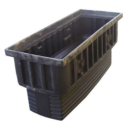
A contractor running a new underground supply to a rear switchboard hits a direction change halfway through the trench, and there's no clean way to pull the cable through without an access point right there. Order a pit that's too small for the number of cables passing through, and the job stalls while a bigger one gets delivered. Getting the size right the first time comes down to two things: how many cables are actually going through it, and how often someone's going to need to open it back up.
Size and depth are decided together on most jobs, but they're not the same question. If you haven't locked in confirming your burial depth yet, that's worth sorting first — this guide picks up from there, on what happens once the pit goes in and which size actually holds up to being opened again and again.
It's a common mistake to size a pit off the trench it's sitting in, rather than what's actually going to be coiled and joined inside it. A single service cable passing straight through needs very little room. The same pit trying to hold a joint, a spare loop for future testing, and a second cable entering from a different angle needs a lot more — even though the trench either side looks identical.
Before ordering, count what's actually going in: how many cables pass through, whether any of them terminate or joint at this point rather than just running through, and whether there's a spare loop being left for future work. A pit sized for a straight pass-through will feel undersized the moment a joint or a second cable gets added later, and re-digging to swap it out costs more than ordering one size up would have.
Schnap's underground cable pit range runs from compact single-service pits through to large distribution pits built for multiple heavy runs. As a general starting point, here's how the range breaks down by what each size is typically suited to:
| Size Tier | Approx. Range | Typically Suited To |
|---|---|---|
| Small | Around 320-420mm | Single service cable, straight pass-through, infrequent access |
| Medium | Around 550-670mm | Multi-cable junctions, direction changes, occasional testing access |
| Large | Around 580-1240mm | Heavier junctions, joints with spare loops, regular access |
| Extra-Large | Around 900-2040mm | Major distribution points, multiple large cable runs |
These pits sit within Schnap's broader range of underground enclosures, and the sizing logic above is a starting point — a Medium pit with one joint and no spare loop can behave more like a Small one in practice, while a Small pit pressed into service for a junction it wasn't sized for gets cramped fast.
A pit that only ever gets opened for an emergency fault doesn't need to be worked in comfortably. A pit that's going to have a technician kneeling over it every time cabling gets tested or extended does — cramped access means more time on site and a higher chance of damaging a joint while working around it. If maintenance or testing access is going to be routine rather than rare, it's generally worth sizing up from what the cable count alone would suggest, purely to leave room to actually work.
Load rating follows a similar logic to access frequency, but it's about what sits on top of the pit rather than what happens inside it. A pit set into a garden bed or verge that never sees vehicle traffic has different requirements to one installed in a driveway or car park. As a general rule, pits expected to carry any vehicle loading need a higher load class than pedestrian-only locations — check the specific load rating listed against each product before ordering if the pit is going anywhere near driveway or trafficable ground.
Sizing off the trench instead of the cable count. A wide trench doesn't mean a wide pit is needed, and a narrow one doesn't rule out a joint being added later. Count what's going in, not what's around it.
Not leaving room for a spare loop. A pit sized exactly for the cables going through it today leaves no slack for re-termination or future testing — a common regret once the pit's already backfilled around.
Ignoring how often the pit will actually be opened. A pit that's technically big enough but painful to kneel in front of turns a quick job into a slow one every single time it's accessed.
Assuming pedestrian load rating covers a driveway install. If there's any chance a vehicle will drive over the pit — including during construction, before landscaping is finished — the load rating needs to match that, not the finished use.
how many cables can go through a small underground pit?
It depends on the cable diameter and whether the pit is a straight pass-through or a joint point. As a general rule, a small pit around 320-420mm is comfortable for a single service cable running straight through, but gets tight fast once a joint, spare loop, or second cable is added.
is a small pit big enough for a single-phase service run?
For a straight single-phase service cable with no joint at that point, a compact pit such as the 320 x 530mm pit is generally sufficient. If a joint or a spare loop is planned for that access point, size up to a medium pit instead.
do I need a licensed electrician to install an underground cable pit?
Installing the pit itself as a civil element generally doesn't require an electrical licence, but any cabling work connected to it — joints, terminations, or connecting into a switchboard — does need to be carried out or supervised by a licensed electrician under Australian regulations. Check your state's specific licensing requirements before starting.
does the pit depth need to match my conduit depth?
Yes — the pit needs to sit at the same depth as the cable or conduit run it's connecting to, rather than being set at a convenient depth on its own. If you haven't confirmed matching pit and conduit depth for your run yet, that's worth locking in before finalising which pit to order.
Related Reading
Trade pricing and same-day dispatch from Kingsgrove NSW across the full underground cable pit range, from single-service sizes through to large distribution pits.
Find the full underground cable pit range at Schnap — trade pricing and same-day dispatch from Kingsgrove NSW.
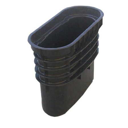
A sparky running 25 metres of active cable from the switchboard to a new pool pump doesn't think about depth until the trench is already half dug. Get the cover wrong and you're either re-digging before inspection or explaining to the certifier why the tape's not where AS/NZS 3000 says it should be. Depth decides more than compliance -- it decides whether you need a straight run or something to break it up along the way.
As a general rule, the required cover over a buried cable changes depending on what's above it. A run under a garden bed doesn't carry the same risk as one under a driveway that gets driven over daily, so the standard treats them differently -- shallower cover is generally acceptable where nothing heavy sits on top, and deeper cover (or added mechanical protection) is expected wherever vehicles or foot traffic are a factor.
| Location Type | Typical Cover Depth (trade rule of thumb) |
|---|---|
| Garden bed / lawn | Commonly around 450-600mm |
| Driveway / vehicle area | Typically deeper, often needing conduit or slab protection as well |
| Footpath / public access | Usually deepest, plus conduit per the local supply authority's rules |
These are common trade rules of thumb, not a substitute for checking the current AS/NZS 3000 clause and your local supply authority's requirements before you dig. Where the required cover genuinely can't be achieved -- rock close to the surface, existing services in the way -- the standard typically allows extra mechanical protection to make up the difference, which is usually where conduit earns its keep.
[!] Compliance note: Depth requirements are only part of the picture. Marking tape, mechanical protection, and warning signage requirements typically apply on top of cover depth -- confirm the full set of conditions with your certifier before backfilling.
Depth tells you how far down the cable sits. It doesn't tell you what happens at the point where the run changes direction, or where a future technician needs to get back into the trench without digging up the whole yard. That's a separate decision, and it's the one that trips up contractors who've only thought about cover so far.
If the run from switchboard to pump has to jog around an existing tree root or turn 90 degrees to reach the meter box, forcing that bend underground with nothing but conduit fittings gets harder to justify the tighter the angle gets. This is usually the point where sizing your underground cable pit becomes the more practical call -- a pit gives you a clean access point for the direction change instead of relying on the conduit alone to take the strain.
The same logic applies if you're speccing underground enclosures for a job with more than one service point along the run -- a junction pit at the branch point is usually easier to justify at design stage than trying to retrofit access later once the trench is backfilled and the lawn's grown back over it.
Related Reading
Measuring from the wrong reference point. Cover depth is usually measured from finished ground level, not from the bottom of the trench as originally dug -- if topsoil or pavers go back on top later, the cable needs to sit deep enough to still meet cover once that finished surface is in place.
Assuming garden-bed depth applies everywhere on the run. A single cable run often crosses more than one surface type -- lawn for most of its length, then a short stretch under a paved path. Treating the whole run at the shallower garden-bed depth misses the deeper requirement where it crosses the path.
Skipping the direction-change decision until the trench is dug. By the time the trench is already in the ground, adding a pit for a bend that should've been planned for means extra digging and a delay waiting on stock. This is a decision worth making at the planning stage, not on site with the trench already open.
Forgetting mechanical protection where depth is compromised. Rock, existing services, or root systems close to the surface sometimes make full cover depth impractical. Skipping the extra conduit or slab protection that's meant to compensate is a common shortcut that doesn't hold up at inspection.
Not accounting for future access. A run with no pit at all works fine until something needs fixing three years later, and the only way in is digging up the whole trench again. A single access point at a logical spot -- usually where the run bends or branches -- saves that headache.
Do I need a licensed electrician to bury mains cable under AS/NZS 3000?
As a general rule, yes -- underground work on active electrical cable is licensed work in every Australian state, and depth and cover requirements are inspected as part of that. Check with your local licensing body for the exact scope before starting.
Is there a minimum size underground cable pit I can use if I only need it for one bend?
For a single direction change on a smaller residential run, a compact pit is usually enough -- the 419 x 155 x 350mm underground cable pit covers most single-bend jobs without oversizing the excavation.
How do I know if a direction change needs a pit instead of a sweep bend underground?
In practice, a gentle sweep bend within conduit's rated radius usually doesn't need a pit. Tighter turns, or any point where you'd want future access, are where a pit typically makes more sense than relying on the bend alone.
What size pit do I need for a single 90-degree turn on a residential run?
It depends on cable size and how many runs pass through the same point -- our guide on picking the right pit size breaks down sizing by scenario.
Does the depth rule change if I'm running cable under a garden bed instead of a driveway?
Yes, typically -- garden beds generally allow shallower cover than areas that see vehicle traffic, since the risk of the cable being disturbed or damaged is lower.
What if the pit needs to handle a bigger cable bundle for a shed subboard?
For runs feeding a subboard with multiple cables converging, step up to something with more room -- the 582L x 393W x 580H underground cable pit handles bundled runs and junction points better than a single-cable pit.
Related Reading
Trade pricing and same-day dispatch from Kingsgrove NSW on the full underground enclosures range.
Find the full underground cable pit range at Schnap -- trade pricing and same-day dispatch from Kingsgrove NSW.

SCHNAP Electrical Wholesaler - clear, upfront pricing that professional electricians trust

Get what you need in seconds. SCHNAP electrical wholesaler makes ordering quick and simple

Fast delivery anywhere - that's guaranteed. SCHNAP electrical wholesalers ship nationwide with same-day dispatch

Track your order every step of the way. SCHNAP electrical wholesale keeps you updated from click to delivery

SCHNAP is Australia's premier electrical wholesaler and electrical supplies, marketing thousands of quality products from leading brands. Trusted for nearly two decades by licensed electricians, contractors, and engineers, our range covers everything from basic electrical components to complex industrial electrical equipment
Our key categories include: LED lighting, designer switches, commercial switchboards, circuit protection, security systems & CCTV, and smart home automation
All products are certified to Australian standards (AS/NZS), backed by our 30-day, no-questions-asked return policy. Our expert technical team helps you quickly source the right solution for any residential, commercial, or industrial project, with daily dispatch from our Sydney electrical warehouse delivering Australia-wide
SCHNAP offers the most comprehensive electrical product range, with full technical specifications, application details, installation requirements, compliance standards, and warranties — giving professionals total confidence in every purchase


