




Kingsgrove Branch:
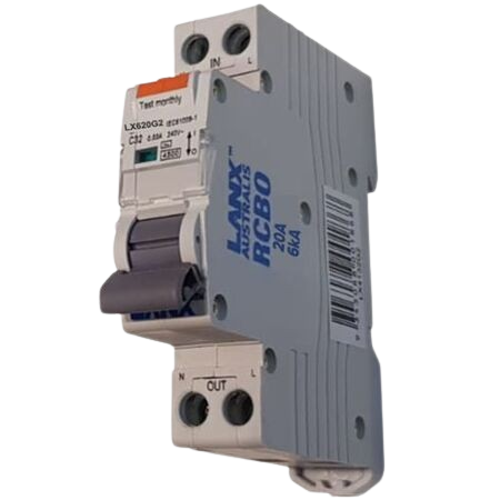
You’re at the switchboard with a circuit that needs residual-current protection, and the choice comes down to two familiar options: an RCD with separate overcurrent protection, or an RCBO that combines both functions. The difference matters because the devices protect against different faults and affect how the circuit behaves when something goes wrong.
The practical question is not simply rcbo vs rcd as a product comparison. It is whether the circuit needs residual-current protection only, or residual-current protection together with overload and short-circuit protection in the same device. For broader context on the products available in this family, see the LANX electrical range.
The easiest way to separate the two is to look at the protection functions built into each device.
| Device | Residual-current protection | Overload protection | Short-circuit protection |
|---|---|---|---|
| RCD | Yes | No | No |
| RCBO | Yes | Yes | Yes |
An RCD monitors for an imbalance between current flowing out and returning through the circuit. When residual current reaches the device’s operating threshold, it disconnects the circuit. It is therefore focused on residual-current protection rather than protecting the conductors from overload or short circuit.
An RCBO adds overcurrent protection to that residual-current function. In practical terms, it combines the job normally associated with an RCD and an MCB into one protective device. That distinction is the key to understanding the difference between rcd and rcbo.
An RCD is there to detect residual current. That makes it a safety device for faults where current is escaping from its intended path, such as a leakage fault associated with insulation failure or contact with an unintended conductive path.
What it does not do is protect the circuit from every type of overcurrent event. An RCD does not replace an MCB for overload and short-circuit protection. Where those protections are required, the circuit still needs appropriate overcurrent protection alongside the RCD.
Trade point: An RCD and an MCB solve different protection problems. Seeing “RCD protection” on a circuit does not mean the circuit is automatically protected against overload and short circuit.
That distinction is worth keeping clear when checking an existing switchboard or planning a new circuit. The protection arrangement has to be assessed as a complete circuit, not by looking at one device in isolation.
An RCBO combines residual-current protection with overcurrent protection. That means the same device can respond to residual-current faults while also providing protection against overload and short circuit, subject to its specified ratings and characteristics.
This combination can make circuit protection more straightforward where each individual final circuit needs its own residual-current protection. It also means a fault on one protected circuit can be isolated without relying on one shared residual-current device to cover several downstream circuits.
LANX’s current RCBO selection illustrates this integrated approach. The LANX 20A single-pole RCBO, for example, is specified as a 20A 1P RCBO with 30mA Type A detection and 6kA breaking capacity. The exact rating and configuration still need to match the circuit and installation requirements.
The buying decision becomes much easier once the circuit is considered first.
An RCD can make sense where the protection design already includes suitable MCB or other overcurrent protection for the circuit. In that arrangement, the devices have separate jobs: the MCB handles overload and short circuit, while the RCD handles residual current.
The advantage is flexibility in how the switchboard is configured, particularly where an existing board already uses a separate RCD arrangement. The important point is that the complete protection scheme must still provide the required functions for the circuit.
An RCBO is often the more direct choice when the circuit needs both overcurrent and residual-current protection and you want those functions integrated into one device. This can be particularly useful where individual circuit protection is preferred or switchboard space is a consideration.
It also changes fault isolation. With individual RCBO protection, a fault on one circuit can trip that circuit’s protective device rather than necessarily disconnecting several downstream circuits through a shared RCD arrangement.
The right choice depends on more than whether the product says RCD or RCBO. Check the circuit arrangement, conductor protection, rated current, pole configuration, residual-current characteristics, breaking capacity and the requirements that apply to the installation.
For example, choosing a 20A RCBO does not mean the circuit should automatically be protected at 20A. The protective-device rating must be appropriate for the cable, installation conditions and circuit design. For the MCB side of that selection process, the Lanx MCB rating guide covers how current rating and circuit conditions affect breaker selection.
Consider a new final circuit where residual-current protection is required and the board is being configured circuit by circuit. The first question is whether you need both residual-current and overcurrent protection for that circuit.
If the answer is yes, an RCBO provides both functions in one device. You then select the appropriate current rating, poles, residual-current characteristics and breaking capacity for the installation.
If the switchboard already uses a suitable RCD arrangement and separate MCB protection, an RCD may still be the appropriate part of that overall design. The important distinction is that an RCD should not be treated as a replacement for the circuit’s required overcurrent protection.
Selection rule: Start with the protection functions the circuit requires, then select the device configuration and ratings. Do not start with whichever breaker happens to be available in the van or switchboard.
What is the difference between RCD and RCBO?
An RCD provides residual-current protection, while an RCBO combines residual-current protection with overcurrent protection for overload and short circuit. An RCD therefore normally forms part of a protection arrangement that also includes suitable overcurrent protection.
Can an RCD replace an RCBO?
Not as a direct one-for-one substitution. An RCD and RCBO perform different protection functions, so replacing one with the other depends on the complete circuit design and the protection already provided elsewhere.
What type of RCBO suits a 20A single-pole circuit?
A product such as the LANX LX620G2 20A RCBO is specified as a 1P 20A device with 30mA Type A detection and 6kA breaking capacity. The final selection must still match the circuit design and installation requirements.
Does an RCD protect against short circuit?
No. An RCD is intended for residual-current protection. Short-circuit and overload protection requires appropriate overcurrent protection, such as an MCB or the overcurrent function incorporated into an RCBO.
Does replacing an RCBO require a licensed electrician in NSW?
Electrical wiring work in NSW must be carried out by, or under the supervision of, a licensed electrician. Switchboard protection work should therefore be handled within the applicable licensing and compliance requirements for the job.
Is 30mA always the correct RCD or RCBO sensitivity?
No device rating should be selected automatically from a general rule. Residual-current sensitivity must be appropriate to the circuit, equipment and applicable installation requirements. Check the specific job rather than assuming one sensitivity suits every application.
LANX RCBO options are available with trade pricing and same-day dispatch from the Kingsgrove NSW warehouse. Check the individual product specifications before ordering to make sure the configuration matches the circuit.
Need the right rcbo vs rcd for the job? Browse the LANX range at Schnap.
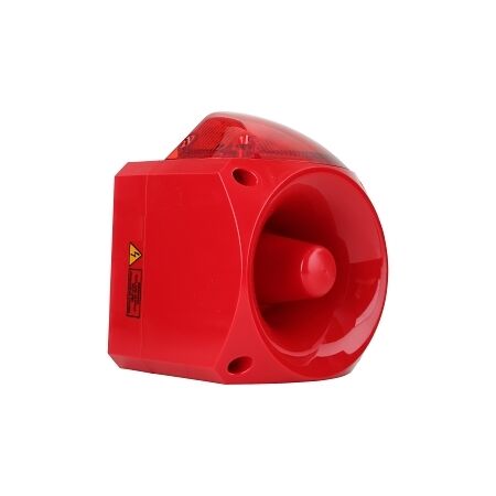
You’re commissioning a plant area where an operator needs to see and hear a warning from the same point, but the obvious-looking beacon on the shelf may not suit the voltage, environment or sound level. A sounder beacon solves that combined signalling problem, but the useful specification is not just the headline dB figure.
For a typical industrial installation, start with the actual warning scenario, then work through sound output, tone selection, supply voltage, IP rating, visual indication and mounting. The broader bells sirens screamers range covers several signalling formats, so choosing by application is more reliable than choosing by appearance.
Picture a machinery area where the warning needs to be recognised quickly from across the floor. The unit has to provide a visible signal under normal plant lighting, while the audible warning needs to remain noticeable against machinery noise. That immediately rules out treating every beacon, buzzer and siren as interchangeable.
A sounder beacon combines two jobs in one device: visual indication and audible warning. That can simplify an installation where space, wiring points or operator recognition are concerns. It also means the selection has to satisfy both sides of the warning function rather than optimising only the light or only the sound.
For example, a 105dB IP66 sounder beacon with a 10-60V DC supply can make more sense on a machine or control installation than a lower-output unit simply because the latter is smaller. Conversely, a very high-output device is not automatically the right answer if the installation does not need that level of acoustic output.
[!] Selection note: Do not choose a warning device from dB alone. The supply voltage, enclosure rating, mounting format and required visual indication can eliminate an otherwise suitable-looking model.
Related Reading
Once the job scenario is clear, narrow the shortlist using the specifications that affect whether the device will work where you are installing it.
A higher sound level can be useful in a noisy industrial area, but bigger is not automatically better. Think about where the sound has to be recognised and what competing noise exists around the installation. The catalogue includes devices ranging from more compact 80dB-class sounder solutions through to industrial horns and sounders exceeding 120dB, giving installers room to match the device to the environment rather than applying one number to every job.
For the audible side of the warning decision, see the warning sounder selection article for a closer look at sound output, tones, voltage and mounting.Selectable tones matter when the warning has to be distinguished from other alarms or plant sounds. A multi-tone unit can give more flexibility during commissioning, while a simpler fixed-tone solution may be entirely adequate where there is only one warning condition.
Check the actual control or supply voltage before choosing the device. The available range in this category includes low-voltage DC models as well as higher-voltage AC units, so voltage mismatch is an easy way to end up with a product that looks ideal on paper but does not suit the installed circuit.
| Selection factor | What to check | Why it matters |
|---|---|---|
| Sound output | Required dB level for the installation | The warning must remain noticeable in the real operating environment. |
| Tone | Fixed or selectable tones | Helps distinguish the warning from other plant signals. |
| Voltage | AC or DC and nominal supply | Prevents selecting a unit that does not match the circuit. |
| IP rating | Required environmental protection | The enclosure needs to suit the installation conditions. |
| Mounting | Panel, wall or surface mounting | The mounting format needs to fit the physical installation. |
| Visual signal | Colour and steady/flashing operation | The operator needs to recognise what the visual indication means. |
This is where a basic indoor-looking beacon can become the wrong choice. If the installation is exposed to dust, water or harsher industrial conditions, the enclosure rating deserves the same attention as sound output. For an outdoor or washdown-prone location, an IP-rated model such as an IP66 sounder beacon may be more appropriate than a lower-rated panel device.
Look at the physical point where the warning must be seen and heard. Panel-mounted devices suit control enclosures and operator stations, while surface or wall-mounted units can be more appropriate when the signal needs to project into an open plant area. Mounting is not just a mechanical detail; it affects visibility, accessibility and how the warning integrates into the installation.
For installations using horn-based audible warning equipment, speaker cable sizing may also become part of the wiring decision.
[!] Installation note: Make sure the selected sounder beacon matches the equipment supply and the physical environment. Where the installation involves regulated electrical work, use the appropriately licensed electrical trade and follow the applicable requirements for the jurisdiction.
The main practical advantage of a sounder beacon is that one device can provide the two signals the operator needs. That is particularly useful when the warning point is compact or when combining audible and visual indication makes the alarm easier to recognise.
A combined unit can also simplify the selection process. Instead of trying to coordinate a separate horn with a separate beacon, you are choosing one assembly whose light and sound functions are designed to operate together. The trade-off is that the combined unit still has to meet the requirements of both functions.
Choosing by dB alone. A high sound output does not compensate for the wrong voltage, enclosure rating or mounting arrangement. In a real plant, the right device is the one that fits the whole installation.
Ignoring the existing control voltage. It is easy to focus on the warning function and overlook whether the available circuit is AC or DC. Check the supply before narrowing the product choice.
Using an indoor-style unit in a harsh location. A beacon mounted where it sees moisture, dust or other environmental exposure needs the appropriate enclosure protection. A visually similar lower-rated model is not an equivalent substitute.
Overlooking the visual signal. The light colour and flashing or steady operation should support the warning function and the way operators recognise the alarm, not simply match the colour that happens to be available.
Using more functionality than the job needs. Selectable tones, very high sound output and combination features are useful when the installation benefits from them. They should not become the reason for choosing a more complex unit when a simpler solution already satisfies the warning requirement.
Can I use a 24V DC sounder beacon on a 24V control circuit?
Only where the selected device is rated for the actual supply and installation conditions. For example, a model specified for 24V DC is intended for that type of supply, but the rest of the device specification still needs to suit the job.
Is a 105dB sounder always better than an 85dB unit?
No. The suitable output depends on the environment and how the warning needs to be recognised. A higher rating may be useful in a noisy area, but excessive output is not automatically the correct specification.
What should I check for an outdoor sounder beacon?
Check the enclosure rating, supply voltage, mounting format and the required sound and visual output. An IP66 sounder beacon is one example of a higher-protection configuration available in the range.
Do I need a licensed electrician to install a fixed sounder beacon?
Licensing requirements depend on the electrical work and jurisdiction. For fixed electrical installation work, use the appropriately licensed electrician and follow the applicable state or territory requirements.
Does a panel-mounted sounder beacon need an IP-rated enclosure?
That depends on the environment and the enclosure arrangement. The sounder beacon itself should have an appropriate rating for its exposure, and the complete installation should suit the conditions where it is installed.
Should I choose selectable tones for every industrial alarm?
Not necessarily. Selectable tones are useful when the warning needs to be distinguished from other signals or when commissioning requires flexibility. A fixed-tone device can be sufficient for a straightforward single-warning application.
What is the advantage of a combined light and sound alarm?
It provides audible and visual indication from one device, which can be useful where the warning needs to be recognised quickly or where the installation benefits from a combined unit. Options such as this 24V light-and-sound alarm illustrate that combined approach.
When would I use a higher-output industrial horn instead of a compact panel sounder?
The decision comes back to the warning environment and the installation point. A larger industrial horn can make sense where the warning needs stronger acoustic projection across plant areas, while a compact panel sounder may be more appropriate at a local operator station. A 126dB industrial horn is an example of a much higher-output option.
Once the warning scenario and specifications are clear, the final shortlist is usually much smaller. That is the point of the selection process: not to compare every sounder beacon in the catalogue, but to identify the units that actually fit the job.
Related Reading
Schnap carries a broad range of audible and visual signalling products for trade applications, with trade pricing and same-day dispatch from Kingsgrove NSW.
Browse the full sounder beacon range at Schnap -- trade pricing, trusted brands, dispatched same day from Kingsgrove NSW.
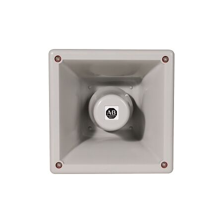
A machine alarm can be technically correct and still fail its job when nobody hears it. Picture a production line where several machines are running at once, operators are moving between work areas, and the control panel is some distance from the point where the warning needs to be noticed. In that situation, choosing a warning sounder means matching the device to the actual working environment rather than simply choosing the highest dB figure.
For systems that also need a visual warning, the selection process overlaps with the factors covered in this sounder beacon selection article. For an audible-only application, however, the decision comes down to sound output, tone, voltage, mounting and the environment around the device.
The first thing to establish is not the product model. It is the location of the people who need to recognise the warning.
A compact panel buzzer may be perfectly practical when the operator is standing close to the enclosure. The same device can be a poor choice if the warning has to be heard across a workshop with motors, compressors or other machinery operating nearby.
That is why a useful selection process starts with four questions: how far does the sound need to travel, how noisy is the surrounding area, where will the device be mounted, and what supply is already available? Once those answers are clear, the product shortlist becomes much smaller.
[!] Do not select a warning sounder from dB alone.
Sound output is only one part of the decision. Tone, mounting position, background noise, supply voltage and environmental protection all affect whether a warning device is appropriate for the installation.
The warning sounders in this range cover a wide spread of output levels. At the lower end is a 95dB panel-mount piezo buzzer, while the range also includes electronic horns and industrial motor-driven sirens specified at 135dB and 145dB.
That spread is useful because the right device depends heavily on the application. A local panel indication does not necessarily need the same output as an alarm that must project across a larger plant area.
Consider a warning point on a machine located inside a busy workshop. If the sounder is mounted directly on the control enclosure and the operator is normally nearby, a compact local device may be appropriate. If the warning must be recognised from further away, a higher-output electronic or industrial horn may make more sense.
The important distinction is between sound output and useful warning coverage. A larger dB number does not automatically compensate for poor positioning or an unsuitable alarm tone.
Related Reading
Two warning devices can have similar sound-output ratings but behave very differently from an operator's point of view. Tone selection matters because the warning needs to stand out from normal equipment noise and be recognisable as an alarm.
Some products provide only a small number of tones, while others provide many selectable tones. A 3-tone, 2-stage electronic horn may be suitable for a straightforward machine sequence. A 64-tone sounder gives the control-system designer more choice when different alarm conditions need to be distinguished.
More tones are not automatically better. The practical goal is to choose an alarm pattern that fits the machine or process and remains easy for operators to identify. For an industrial alarm horn, the sound selection should therefore be considered alongside how the alarm is used rather than treated as a specification to maximise.
Voltage is one of the easiest details to get wrong when several visually similar warning devices are being compared. The correct sounder has to match the actual supply available at the machine or control panel.
| Device example | Supply | Why it matters |
|---|---|---|
| Panel-mount piezo buzzer | 12–24V AC/DC | Suitable for installations where a compact local warning is required and the supply falls within this range. |
| Electronic horn | 10–30V DC | Provides a wider DC input range for compatible control systems. |
| Industrial horn | 24V AC | Requires a compatible 24V AC supply. |
| Nexus sounder | 10–60V DC | Useful where a wider DC input range is required. |
| Nexus sounder | 110–240V AC | Designed for a compatible mains-voltage supply. |
Before ordering, confirm three things: the control-system voltage, whether the supply is AC or DC, and the actual input range accepted by the selected model. Do not assume that a nominally similar device uses the same supply.
Once sound and voltage are established, look at how and where the warning device will be installed. A panel-mounted buzzer, surface-mounted horn and flush-mounted horn solve different physical installation requirements.
For an enclosure-mounted machine alarm, a panel device can keep the installation compact and straightforward. Where the sounder needs to project into the surrounding plant area, an industrial horn may be more suitable. A surface or flush format can then be selected according to the mechanical arrangement of the installation.
Environmental protection also deserves attention. The listed products include examples with IP54, IP55 and IP66 protection. The appropriate rating depends on the environment in which the device is actually installed and the manufacturer's stated application requirements.
An IP66-rated device may therefore be a more suitable option for a more exposed installation than an IP54 model, but the rating should never be considered in isolation. The mounting location, enclosure arrangement and overall installation still need to be appropriate for the environment. For the visual side of that decision, see the flashing beacon LED selection article.
By this point, the choice is usually clearer because each device type solves a different problem.
The right choice is therefore not the device with the biggest specification. It is the device that gives the required warning at the required location while fitting the available power supply, mounting arrangement and environmental conditions.
Choosing the loudest model available. A very high-output siren can be unnecessary when the warning only needs to be heard beside a machine. The actual listening point should drive the decision.
Matching the voltage but not the supply type. Seeing “24V” on both products does not make them interchangeable. A 24V AC device and a 24V DC device still have different supply requirements.
Ignoring the alarm tone. The sound needs to be recognisable in the working environment. More selectable tones can provide flexibility, but only when that flexibility is useful to the alarm strategy.
Using a panel buzzer where an area warning is required. A local enclosure indicator may not provide the warning coverage needed across a busy plant or workshop.
Overlooking mounting and IP requirements. A sounder that fits electrically can still be the wrong choice if its mounting format or environmental protection does not suit the installation.
Leaving the wiring decision until last. Where a warning system involves speaker-based equipment or a longer cable run, the wiring arrangement should be considered alongside the warning-device selection.
Is 95dB enough for a machine warning sounder?
It can be suitable for a local warning application, but the answer depends on where the sound needs to be heard and how much background noise is present. A higher-output device may be more appropriate for a larger or noisier area.
Do more alarm tones make a warning sounder better?
Not necessarily. Multiple tones are useful when different alarm conditions need to be distinguished, but the most important requirement is selecting a sound that is appropriate and recognisable for the application.
Can I use a 24V AC warning sounder on 24V DC?
Do not assume that AC and DC versions are interchangeable. Confirm the exact supply type and input range specified for the selected sounder before installation.
Do I need a licensed electrician to install a warning sounder?
Electrical installation work can be subject to licensing and compliance requirements depending on the Australian jurisdiction and the scope of the work. Where licensed electrical work is required, use an appropriately licensed electrician and follow applicable requirements and manufacturer instructions.
Is IP66 better than IP54 for an industrial warning sounder?
IP66 provides a different level of enclosure protection from IP54 and may be more appropriate for a more exposed installation. The correct choice still depends on the actual environment and the product's specified application.
Should I use an electronic horn or motor-driven siren?
Match the device to the warning requirement. Electronic horns provide a range of output and tone options, while the motor-driven sirens in this range are specified for substantially higher output. The surrounding environment and required warning coverage should determine which is appropriate.
For the wider range of audible warning devices and related bells sirens screamers, see the products below.
Schnap stocks warning sounders for machinery, plant and control-panel applications, with trade pricing and same-day dispatch from Kingsgrove NSW. Select by sound output, tone capability, supply voltage, mounting format and environmental protection.
Browse the full warning sounder range at Schnap for trade pricing and same-day dispatch from Kingsgrove NSW.
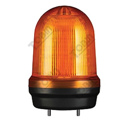
The machine is running, the control panel is working, and then someone on the other side of the plant floor needs to know there is a warning condition. The problem is not whether an indicator exists; it is whether the visual signal is obvious from the place where it needs to be seen.
Choosing a flashing beacon LED comes down to a few practical decisions: what the light needs to communicate, which colour and operating mode fit the signalling scheme, what voltage is available, where the beacon will be mounted, and what the environment will throw at it. The bells sirens screamers category includes audible and combined devices as well, but this article stays focused on visual warning selection.
A beacon mounted inside a control enclosure may be perfectly visible to the electrician standing at the panel and almost useless to an operator several metres away. That is why the physical warning point should be decided before comparing beacon models.
Think about the actual sight line. Is the operator looking across a production area, along a plant aisle, towards a machine, or back at a control cabinet? Ambient lighting also matters. A signal that is clear in a dim room can be much harder to pick out in a brightly lit production space.
This is also where visual and audible selection start to separate. If the installation needs both, the warning sounder selection process needs to consider sound output and tones as well as the visual indication. For this article, the light remains the primary decision.
[!] Field check:
Before selecting the beacon, stand where the operator or affected person will actually be working. If the warning cannot be picked out from that position, changing the colour or flash mode may not solve the real problem if the mounting location itself is wrong.
Related Reading
The choice between flashing and steady indication should follow what the signal is meant to tell the operator. A flashing light can be useful where the visual signal needs to attract attention to an alarm or change of condition. A steady light can be easier to interpret when the purpose is to show an ongoing machine or system state.
Do not assume that flashing is automatically the better warning. A site may already have a defined signalling convention where different colours or operating modes correspond to particular conditions. In that situation, the beacon needs to match the existing logic rather than introducing a new signal simply because it is more noticeable.
The supplied range includes products specified for steady operation as well as products with steady/flashing capability. That gives the installer a choice between a fixed visual state and a more attention-grabbing signal where the application calls for one.
Colour should be treated as part of the control philosophy, not as a cosmetic choice. A beacon may be physically interchangeable with another colour, but the meaning attached to that colour can vary between machines, sites and applications.
The product options supplied for this article include amber, red, green, blue and orange LED configurations. That variety is useful where a project already assigns different colours to different conditions or stages of operation.
For a general warning scenario, amber is a practical example. The 80mm LED steady/flashing signal is specified with an amber LED, 110-240V AC supply and IP65 protection. Other supplied options provide red, green, blue or orange indication for different signalling requirements. Confirm the colour against the project's existing documentation before treating any colour as the default.
Voltage mismatch is one of the easiest mistakes to avoid and one of the easiest to make. Two beacons can have almost identical bodies and still require completely different supplies.
Start with the circuit that will actually power the beacon. Confirm the nominal voltage, whether the source is AC or DC, and the manufacturer's stated operating range. Do this before selecting the unit on colour or physical size.
| Supply scenario | What to confirm | Selection implication |
|---|---|---|
| 110-240V AC | Nominal AC supply and product input range | Select models whose published input range matches the supply. |
| 24V DC | DC input rating and operating range | Do not assume every 24V beacon has the same input requirements. |
| Wide-range DC | Minimum and maximum stated DC voltage | A broad input range can simplify selection across different control applications. |
The supplied range illustrates the spread. The 80mm Tobin beacon is specified for 110-240V AC, the Klaxon KL2496R is specified for 17-60V DC, and the KL980620 covers 10-60V DC. The Moflash LED Sounder Cap listed here is specified for 20-30V AC/DC. Those differences should be checked at the product level rather than inferred from physical appearance.
Once the electrical requirement is known, look at the mounting position. A wall-mounted beacon makes sense where the signal needs to sit on a vertical surface, while a surface-mounted unit may suit a machine or enclosure. The objective is the same: get the signal into the operator's line of sight without creating a difficult installation.
The 80mm wall-mount LED signal is a useful example of how mounting format changes the product choice. It retains the same basic warning-light concept but is specifically listed as a wall-mount version, which can make more sense where the warning point sits on a vertical surface rather than directly on a machine or enclosure.
Also consider how much of the beacon will remain visible after installation. Cable entries, brackets, nearby guards and machine structures can all reduce the practical viewing angle. A technically compliant mounting location can still be a poor warning location if the beacon is hidden from the people who need to see it.
IP rating matters when the beacon is exposed to dust, water or harsher industrial conditions. The correct question is not simply which model has the highest number, but what the installation environment actually requires.
Several supplied products are rated IP65, while the Klaxon KL980620 is rated IP66. Those ratings indicate different enclosure protection characteristics. If the beacon is mounted in an area exposed to more demanding conditions, use the product specification and site requirements to decide whether the available rating is adequate.
Temperature can also become relevant in outdoor or industrial locations. Where the manufacturer specifies an operating temperature range, compare it with the expected installation conditions. Do not assume that all beacons in the same physical size have the same environmental performance.
For a typical industrial warning installation, the shortest path to the right beacon is to work through the decisions in order. Define where the warning needs to be seen. Confirm what the visual signal is supposed to mean. Select the required colour and steady or flashing operation. Then match the supply voltage, mounting format and environmental protection.
That approach prevents the common problem of choosing a beacon because it looks right and only later discovering that it does not suit the circuit or physical installation. It also keeps the visual decision separate from audible-warning selection. Combination devices may cover both functions, but the visual requirement should still be defined independently.
Should I use a flashing or steady beacon for a machine warning?
Use the operating mode that matches the site's signalling strategy. Flashing can help attract attention to an alarm or change, while steady operation may be intended for an ongoing condition.
Can I use any beacon colour if the light is easy to see?
No. The colour should match the meaning assigned to the signal by the project or site. Visibility alone does not define what the signal is supposed to communicate.
Can I use a 24V DC LED beacon on any 24V control circuit?
Not automatically. Check the exact DC input specification and operating range of the beacon before connecting it. The circuit voltage also needs to match the device's published supply requirements.
Do I need a licensed electrician to install a fixed warning beacon?
Licensing and compliance requirements depend on the nature of the electrical work and the jurisdiction. Where the work is regulated electrical installation work, use an appropriately licensed electrician and follow the applicable requirements.
Is IP66 always better than IP65 for an LED warning beacon?
Not necessarily. The correct rating depends on the environment and the level of protection required. IP66 provides a different protection level from IP65, so select the rating that matches the actual exposure.
Is wall mounting better than surface mounting for a warning beacon?
Neither is universally better. The mounting format should place the beacon where the warning is visible and allow the product to be installed as intended for the location.
Do I need a beacon if the machine already has an audible alarm?
A visual warning can add another way to recognise a condition, particularly where the person affected may not clearly hear the audible signal. Whether both are required depends on the application and the site's warning strategy.
When is a combined sounder beacon better than a separate light?
A combined device can make sense where the installation needs both audible and visual warning from the same point. Consider the audible and visual requirements separately before selecting a combined unit.
Once the warning point, visual logic, supply and environment are defined, the product shortlist becomes much smaller. The options below can then be compared against the requirements of the actual installation rather than against one another on appearance alone.
The range includes LED warning and combination signalling products across mains and low-voltage supplies, multiple colours and different mounting or operating formats. Trade pricing is available, with same-day dispatch from Kingsgrove NSW.
See the full flashing beacon led range at Schnap.
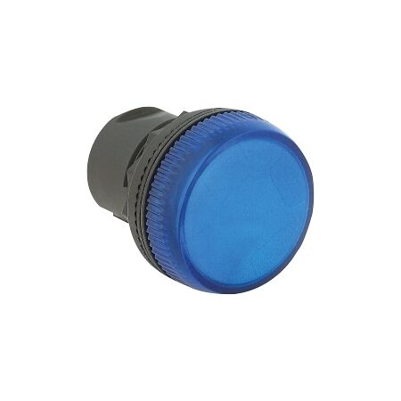
You have a control panel on the bench, the circuit is already defined, and the last thing to settle is the indication: what should the operator actually see when the equipment is energised, running or in a fault state? That choice looks simple until voltage, mounting size, colour and environment all need to line up.
Pilot lights are small components, but choosing the wrong one can mean extra panel work, an awkward fit or an indicator that does not match the electrical requirement. The same control-panel job may call for a compact 12mm indicator in one location and a larger metal, sealed unit in another. For the broader panel-selection context, see choosing the right switch rating.
The first check is not the diameter of the indicator. It is the circuit it has to indicate. A pilot light needs to match the voltage and electrical arrangement of the circuit where it will be used.
The product range for this category includes 24V DC indicators, 24V AC/DC options, 120V and 130V AC/DC units, and 240V AC versions. That spread matters because a visually identical indicator can still be the wrong electrical choice for the circuit.
| What to check | Why it matters |
|---|---|
| Circuit voltage | The indicator must suit the circuit voltage rather than simply fit the panel hole. |
| AC, DC or AC/DC | The product configuration needs to match how the control circuit is supplied. |
| Indicator meaning | Choose a colour and indication function that make sense for the machine or panel sequence. |
| Panel environment | Exposed or harsher locations may need a more robust construction and environmental rating. |
[!] Check the circuit before ordering
Do not choose a pilot light from panel-hole size alone. Confirm the circuit voltage and whether the indicator is intended for AC, DC or AC/DC operation. Where a site specification or equipment manufacturer defines an indicator requirement, that requirement takes priority.
Related Reading
Once the electrical requirement is clear, the next issue is physical fit. A panel builder working with a compact control station may be limited by the available mounting diameter, while a larger machine panel may have more room for a larger indicator and a more substantial front assembly.
The products supplied for this category span 12mm, 18mm, 22mm and 30mm formats. That means the mounting dimension should be treated as a design constraint, not as an afterthought. Re-check the panel cut-out and the existing hardware before selecting the indicator.
A 22mm pilot light can be a practical middle ground when the panel design calls for a conventional industrial control-hole format. Smaller 12mm indicators can make more sense where space is tight, while 30mm units suit applications already designed around the larger mounting format.
Also watch the difference between a complete indicator and an accessory or component intended to work with another assembly. A panel layout can look compatible on paper while still requiring the correct body, lens, or mounting arrangement.
A pilot light is most useful when its meaning is obvious to the person standing in front of the machine. That is why colour should follow the machine's indication logic rather than being selected simply because a particular colour is in stock.
The range includes red, green, amber, blue, yellow, white and clear configurations. A practical panel might use one colour for an operating state and another for a different machine condition. The actual meaning should be consistent with the equipment design and any applicable project or manufacturer documentation.
Push-to-test and test-diode configurations serve a different purpose from a basic illuminated indicator. They can help verify that the indication circuit and lamp function are available to be tested, which can be valuable during commissioning or maintenance. The important point is to choose the function deliberately rather than treating all LED pilot lights as interchangeable.
[!] Keep the indication logic consistent
Colour conventions can vary between machines, sites and project specifications. Follow the documented indication logic for the equipment rather than assuming a colour has the same meaning in every installation.
A pilot light inside a protected control cabinet is not facing the same conditions as one mounted where dust, moisture or regular cleaning are part of the job. That is where construction and environmental rating start to matter as much as voltage and mounting size.
The supplied range includes IP65 and IP66 pilot-light options, including metal-front versions. These products are the more relevant choices when the installation demands a higher level of protection at the panel interface. The exact protection required still needs to be checked against the enclosure, installation environment and project specification.
For a harsher application, do not assume that changing only the lens colour is enough. The construction of the complete indicator and its stated rating need to suit the location. This is especially important where the panel is exposed to moisture, dust or frequent cleaning.
Choosing by diameter alone. A pilot light may physically fit the panel and still be electrically wrong. Confirm voltage and circuit type before locking in the mounting format.
Treating every LED indicator as interchangeable. Voltage, AC/DC configuration, test function and construction can differ even when two indicators look similar from the front.
Using colour without checking the panel logic. A red, green or amber light is only useful when its meaning is clear and consistent with the equipment's indication scheme.
Ignoring the installation environment. A standard indicator may not be the right choice for a location where moisture, dust or cleaning exposure is significant. Check the stated environmental rating before ordering.
Forgetting the panel cut-out already in front of you. Replacing an existing indicator is often easiest when the replacement matches the mounting arrangement. Measure first rather than discovering the mismatch during fit-off.
What voltage should I use for a 24V control circuit?
Use a pilot light that is specifically rated for the circuit voltage and the required AC/DC configuration. The product list includes 24V DC and 24V AC/DC options, so the exact circuit arrangement still needs to be checked before ordering. A 24V AC/DC option from the range is the 22mm dual-colour pilot light.
Do pilot lights need to match the panel switch size?
They need to suit the available mounting arrangement, but there is no single universal indicator size for every panel. The supplied products cover several mounting formats, including 12mm, 18mm, 22mm and 30mm.
Do I need to be a licensed electrician to install a pilot light?
Where the work forms part of fixed electrical installation or other regulated electrical work, licensing and applicable Australian requirements should be followed. The exact requirement depends on the installation and the work being performed, so the responsible licensed electrical professional should confirm the applicable rules for the job.
Should I use an IP66 pilot light outdoors?
An IP66-rated pilot light can be relevant where the installation needs a higher level of protection, but the indicator rating must be considered as part of the complete enclosure and installation. Check the project requirements and environmental conditions rather than relying on the IP number alone.
Schnap supplies pilot lights across several mounting sizes, voltages, colours and configurations for trade and industrial applications. Trade pricing and same-day dispatch from Kingsgrove NSW are available for orders from the range.
For panel work, the right pilot light is the one that matches the circuit first, the panel geometry second, and the operating environment and indication logic after that. That approach keeps the selection practical and reduces avoidable changes at fit-off.
For the complete range, see the electrical pilot light range at Schnap and get same-day dispatch from Kingsgrove NSW.
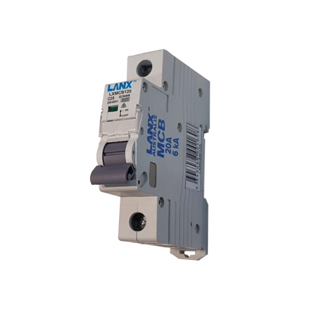
You're back in the switchboard on a kitchen reno, running a new circuit for the dishwasher, and there's a spare 32A breaker already sitting in the board from the old range hood run. It'd save a trip to the van — but that rating was never picked for this load, and swapping it in without checking is exactly how nuisance trips and undersized protection happen. Getting the rating right takes a bit more than grabbing whatever's spare, and it's worth doing properly every time, the same way it's covered across the Lanx Australis electrical range.
An MCB is specified by two things, not one: the amp rating and the trip curve. The amp rating is the obvious part — how much continuous current the breaker will carry before it trips on overload. The curve (almost always C-curve for general power and lighting circuits in a residential or light commercial board) determines how fast it trips on a short-term overcurrent, like a motor starting or an inrush spike. Grab a breaker with the right amps but the wrong curve and you'll either get nuisance tripping on startup loads, or protection that's slower to react than it should be. Every Lanx MCB in this range is C-curve, which covers the vast majority of general circuits — it's the amp rating that changes job to job.
Most general power and lighting circuits in a house run off a single-pole breaker on 230/240V. A lighting circuit typically sits at the lower end — 6A is common where the cable run and fitting load support it. General power circuits, including the dishwasher run from the hook above, commonly land on 20A, which covers a standard GPO circuit wired in 2.5mm² cable under typical run lengths. Heavier single-phase loads — a larger single-element appliance circuit or a higher-draw EV charger — push into 40A or 63A territory, but at that point cable sizing and voltage drop need checking against the actual run, not just the appliance nameplate. Lanx's 1P range covers that whole spread, 6A through to 63A.
| Rating | Poles | Typical circuit |
|---|---|---|
| 6A | 1P | Lighting circuit |
| 20A | 1P | Standard GPO / general power circuit |
| 10A / 32A | 2P | Hot water system, ducted heater |
| 16A / 63A | 3P | Workshop machinery, three-phase equipment |
This is a starting reference, not a substitute for checking cable size and run length against AS/NZS 3000 for the specific job.
Two-pole breakers switch both active conductors on a circuit, which is what a lot of fixed single-phase appliances need rather than a standard 1P/N arrangement — a hot water system or ducted electric heater is a common example. 10A and 32A cover a good spread of these loads, from a smaller instantaneous unit through to a full-size ducted system, but as with single-pole circuits, the rating has to match what the cable run can actually carry, not just the appliance's rated draw.
Three-phase circuits show up most often on workshop equipment, larger compressors, and some EV chargers. Motor loads bring a wrinkle single-phase circuits mostly don't: starting current can spike well above the running current for a short period, and a breaker sized only to the running load will typically nuisance-trip on startup. 16A suits smaller three-phase equipment; 63A covers heavier machinery and main sub-circuits feeding a workshop board. As a general rule, three-phase sizing is worth cross-checking against the equipment's actual starting characteristics rather than the nameplate running current alone.
[!] Compliance note
An MCB on its own protects against overload and short circuit — it doesn't provide earth leakage protection. Where AS/NZS 3000 requires RCD protection for a circuit, that's a separate device (or an RCBO combining both functions), not something an MCB rating alone covers.
Reusing whatever spare breaker is in the board. It's the fastest option on site, but a breaker rated for the old circuit it came from isn't necessarily right for the new one — that's exactly the trap from the dishwasher circuit above.
Matching the breaker to the appliance instead of the cable. A breaker rated higher than what the cable can safely carry defeats the point of the protection — the cable's current-carrying capacity sets the ceiling, not the appliance draw.
Using a single-pole breaker where a double-pole is needed. Some fixed appliances need both actives switched together; a 1P breaker on a circuit that calls for 2P switching leaves one active still live when the circuit's meant to be isolated.
Under-sizing for motor starting current on three-phase loads. Sizing purely to running current on compressor or motor circuits is a common source of nuisance tripping the moment the equipment starts up.
Assuming the MCB has earth leakage covered. As above — an MCB by itself doesn't provide RCD protection, and treating it as if it does is a compliance gap, not just an inconvenience.
What size MCB do I need for a standard GPO circuit?
A 1P 20A C-curve MCB is the common size for a standard general power circuit, though the final rating always depends on the cable size and run length for that specific job.
Can I use a 32A MCB on a circuit wired for 20A?
No — the breaker rating has to match what the cable can safely carry, not be bumped up to whatever's on hand. A 32A breaker on 20A-rated cable removes the protection the cable actually needs.
What's the difference between a C-curve and B-curve MCB?
C-curve breakers, like the 2P 10A C-curve MCB, tolerate a higher short-term inrush before tripping, which suits general power, lighting, and light motor loads. B-curve trips faster on lower overcurrent and is typically reserved for circuits with minimal inrush, which is less common on general trade work.
Do I need a licence to install or replace an MCB in NSW?
Yes — switchboard work is licensed electrical work in NSW, and it's worth confirming current licensing requirements for the specific job against NSW Fair Trading before starting, since scope and exemptions can vary by circuit type.
Does an MCB protect against earth leakage?
No — an MCB covers overload and short circuit only. Earth leakage protection needs a separate RCD, or an RCBO that combines both functions in one device.
What rating three-phase MCB do I need for a workshop machine?
It depends on the machine's running and starting current, but a 3P 16A C-curve MCB is a common starting point for smaller three-phase equipment — always cross-check against the equipment's actual current draw rather than sizing on rating alone.
For more on the full electrical range this sits within, see the Shop section below.
The right rating still comes down to checking cable size and job conditions before ordering — the range below covers the common ratings across single, double, and three-phase.
These MCBs are trade priced with same-day dispatch on in-stock items from the Kingsgrove NSW warehouse.
Find the full circuit breaker rating range at Schnap — trade pricing and same-day dispatch from Kingsgrove NSW.
Lanx Australis is an independent electrical brand carried by more than one Australian wholesaler, and Schnap stocks the range because it spans circuit protection, switchboard hardware, GPOs and cabling accessories at pricing built for high-volume trade jobs. The catalogue also runs into territory most single-brand ranges skip, covering LED lighting and even appliance spare parts like oven elements and stove rings. Here's what's in the range, category by category.
Lanx's miniature circuit breaker range covers single, double and triple pole configurations from 6A through to 63A, all C-curve and 6kA rated. That spread means a switchboard upgrade on a small residential job and a heavier commercial rewire can both be stocked from the same range instead of splitting an order across two brands. C-curve breakers handle the inrush current typical of motors, air conditioners and other inductive loads, which covers most of what turns up on an Australian job site.
Alongside the electrical range, Lanx stocks a genuinely separate appliance parts range — oven elements, plug-in and wired stove elements, and stove ring and socket hardware. It's an unusual pairing for one supplier, but it means an appliance repair call-out and a switchboard job can both be sourced from the same order instead of running two separate accounts.
The RCBO range covers 1P, 1PN and 2P configurations from 10A to 32A, all with 30mA sensitivity and Type A protection, plus higher breaking-capacity 2P options rated to 45kA. RCBOs combine overcurrent and earth leakage protection in a single device, which is standard practice on Australian switchboards where enclosure space is often tight. Several sizes are also available in packs of 12 for board-fit jobs where you're replacing multiple ways at once.
Glands come in both nickel-plated brass and black nylon, in sizes from 12mm through to 63mm, alongside self-locking nylon bushings for cleaning up cable entry points on enclosures. Brass glands with a nickel finish resist corrosion better in exposed or coastal installs, while the nylon range is the more common pick for standard indoor switchboard and enclosure work.
The GPO range covers single and double power points, weatherproof IP53-rated outlets, floor outlets and a specialty RCD-protected outlet, all built around the standard AS/NZS 3112 pin configuration used across Australian homes and job sites. Weatherproof variants have a switched cover, which is the usual requirement for anything mounted outdoors or in a semi-exposed area like a carport or alfresco.
Lighting covers die-cast floodlights from a 20W ultra-slim option through to 120W, all IP65 rated, plus a dimmable LED downlight and aluminium LED strip channel for cabinetry or shelf lighting. The floodlights lean more toward security and work-area lighting around a property than decorative use, given the IP65 rating and die-cast housing built for outdoor exposure.
Wall switches come in 2, 3 and 4-gang configurations, all in white, alongside a blank plate for filling unused switch positions on a board. These are flush-mount plates sized to the switch plate footprint commonly used in Australian wiring, which matters when you're matching into an existing job rather than starting from scratch.
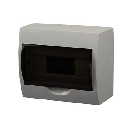
The distribution board range runs from 8-pole through to 24-pole, all surface-mount and IP40 rated for 230/400V systems, plus a 1m slotted DIN rail for mounting breakers and RCBOs inside the board. Pole count is the main spec that matters here — an 8 or 12-pole board covers a straightforward residential job, while the 18 and 24-pole options leave more room for future circuits on a larger property.
The data range covers Cat5e and Cat6 keystone jacks — sold individually or in packs of 20 — plus a patch panel punch-down termination tool kit, and TV/satellite wall plates with F-connector and F-to-PAL configurations. It's a smaller slice of the range, but it means a data point or antenna outlet can go on the same order as the switchboard gear for the same job.
Is Lanx Australis an Australian brand?
Lanx Australis is distributed through multiple Australian electrical wholesalers rather than being a house brand exclusive to one supplier, and its products are sold and warehoused for the Australian market.
Do Lanx circuit breakers and RCBOs meet Australian electrical standards?
Lanx's circuit protection range is built around the pole counts, amperage ratings and breaking capacities used on Australian switchboards, including 6kA MCBs and 30mA Type A RCBOs. As with any brand, check the compliance markings on the specific unit against AS/NZS 61439 and your local wiring rules before installing on a job that requires sign-off.
What's the difference between Lanx's MCBs and RCBOs?
An MCB protects against overload and short circuit only. An RCBO adds earth leakage protection in the same device, which is why RCBOs are increasingly specified for new circuits and renovations under current wiring rules. Lanx stocks both ranges, so you can size a board with either depending on what the job calls for.
Does Lanx make appliance parts as well as electrical products?
Yes — alongside circuit protection, GPOs and lighting, Lanx also stocks a smaller range of oven elements, stove elements and stove ring hardware. It's an unusual combination for one supplier, but it means an electrician doing appliance repairs on the side isn't sourcing parts from a second account.
What warranty applies to Lanx products through Schnap?
Warranty terms vary by product line, so check the individual product page or ask the Schnap trade team for the specific warranty period before ordering in bulk.
All Lanx products ship at trade pricing with same-day dispatch from Schnap's Kingsgrove NSW warehouse.
Find the full Lanx Australis range at Schnap — trade pricing and same-day dispatch from Kingsgrove NSW.
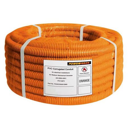
You've just run 20mm flexible conduit from the meter box to a new switchboard on a shed rewire, and now you're staring at the knockout wondering how the conduit is actually meant to terminate. It doesn't just push in and stay put — you need a fitting for that, and picking the wrong one means redoing the job or leaving a gap that fails inspection. Schnap stocks a range of conduit couplings and fittings for rigid runs, but flexible conduit termination has its own quirks worth walking through.
Most rubber flex conduit sold in Australia comes as a plain length — no fitting attached at either end. That's by design: the conduit itself is just the protective sleeve, and the connector is what actually locks it to the enclosure, keeps the entry sealed, and stops the cable inside from chafing against a bare cut edge. Skip the connector and you're left with conduit that's mechanically loose at the termination point, which is exactly where vibration, movement, or a stray knock tends to work it free over time.
A nickel-plated brass rapid connect coupling solves the shed switchboard scenario above — push-fit onto the conduit end, threaded straight into the knockout, no glue or tape needed. For other jobs the right choice depends on the conduit material, the knockout size, and whether the entry needs to stay sealed against dust or moisture.
Not every termination needs the same hardware. A quick-install coupling is fine for a straightforward indoor run, but a threaded adaptor gives you more control when the knockout size doesn't quite match the conduit, or when you're connecting into an enclosure with a specific thread standard already cut.
| Connector Type | Best For |
|---|---|
| Rapid connect coupling | Fast push-fit termination into a matching knockout, no thread cutting required |
| Threaded brass adaptor | Stepping up conduit size to a larger enclosure entry, or matching an existing thread standard |
| Rubber end sleeve | Sealing an exposed conduit end against dust and moisture where a full coupling isn't needed |
PVC and galvanised steel flexible conduit generally take the same connector styles, since the fitting clamps or threads onto the outer profile rather than the core material. The exception is anywhere the conduit is exposed to weather or knocks — steel holds up better there, and it's worth checking the entry point stays sealed either way.
Size mismatches are the single biggest reason terminations end up redone. The conduit diameter has to line up with both the connector and the knockout — and it's easy to grab a fitting that's close enough rather than exact, which usually shows up later as a loose termination or a gap that won't seal properly.
| Conduit Size | Connector Match |
|---|---|
| 20mm | Rapid connect coupling — direct match, no reducer needed |
| 25mm–32mm | PG29-to-32mm brass adaptor covers this range into a 32mm entry |
| 40mm–50mm | Typically needs a larger gland or reducer sized to the specific enclosure — check the knockout before ordering |
If you're working outside this range, measure the knockout itself rather than assuming it matches the conduit label — enclosure manufacturers don't always cut to the same standard.
Assuming the conduit end is already a fitting. The cut end of a length of flexible conduit is just a cut end — it has no thread, no seal, and no mechanical lock on its own. Every termination needs a separate connector, even if the run looks "finished" once it reaches the enclosure.
Mismatching connector size to the knockout. A 20mm coupling forced into a slightly oversized knockout looks fine until the conduit gets a light knock and pulls loose. Measure the actual knockout diameter, not just the conduit size printed on the box.
Skipping the seal on an exposed run. Indoor terminations can often get away without extra sealing, but anything exposed to weather needs the end properly sealed — otherwise moisture tracks straight down the conduit to the switchboard.
Overtightening a brass adaptor onto PVC conduit. PVC flexible conduit is more forgiving than steel, but cranking a threaded adaptor down hard enough to compress it can crack the wall of the conduit right at the termination point — the weakest spot on the whole run.
Terminating before checking you can still pull cable through. Once the fitting is locked down, threading a stiffer cable back through a tight coupling gets a lot harder. Pull your cable through first, then finish the termination.
Do I need a licensed electrician to terminate flexible conduit at a switchboard?
In Australia, any work involving a switchboard connection is electrical work under state licensing rules, so yes — conduit termination at the board should be done or supervised by a licensed electrician, even though the conduit fixing itself is a mechanical task.
What fitting do I need to bring 32mm steel conduit into a switchboard knockout?
A PG29-to-32mm brass adaptor is built for exactly this — it threads into a PG29 knockout and takes 32mm conduit on the other end, so you don't need to redrill the enclosure.
Can I use the same adaptor for PVC and galvanised steel flexible conduit?
Generally yes, as long as the outer diameter matches — most brass adaptors and couplings clamp or thread onto the conduit profile rather than the core material, so the same fitting typically works across both.
Do I need a separate seal if the conduit entry is outdoors?
Yes, in most cases. A rubber end sleeve at the entry point keeps water and dust from tracking down the conduit into the enclosure, which matters most on runs exposed to weather.
For the full range of flexible conduit connectors and related fittings, see the shop section below.
All fittings and conduit below are available at trade pricing with same-day dispatch from Kingsgrove NSW.
Related Reading
Find the full flexible conduit connector range at Schnap — trade pricing and same-day dispatch from Kingsgrove NSW.
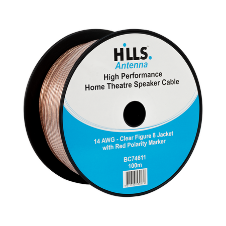
Forty metres from the amp rack to the last zone speaker, and the volume on that run sits noticeably lower than every other zone on the system. It's not a faulty speaker or a loose connection — it's usually gauge. Speaker cable resistance adds up over distance, and picking the wrong AWG for a longer run is one of the more common call-backs on multi-zone PA and security-integrated audio jobs. Here's how to match gauge to run length and system size so every zone sounds the way it should.
Every metre of speaker cable adds a small amount of electrical resistance. On a short run that resistance is negligible, but stretch the same gauge out past 20-30 metres and it starts eating into the amp's output before it ever reaches the speaker. The amp doesn't know the difference — it's still pushing the same signal — but the speaker at the end of a long, thin run gets less power and less clarity than one wired closer to the rack.
This is why gauge isn't just a spec on a datasheet. It's the difference between a zone that sounds even with the rest of the system and one that quietly underperforms until someone notices during a walkthrough and asks why one corner sounds thinner than the rest.
As a general rule, 16 AWG covers the majority of standard runs — ceiling speakers, background music zones, and most single amp-channel runs under about 15 metres. It's the gauge stocked in the highest volume for a reason: it's the right fit for most jobs without over-speccing the cable.
Once a run pushes past 15-20 metres, or you're feeding a zone with a lower-impedance speaker load, 14 AWG starts to matter. The thicker conductor keeps resistance lower over distance, so the speaker at the far end still gets the power the amp is sending. This is typically the gauge worth reaching for on warehouse runs, long corridor zones, or any commercial job where the cable run is genuinely long rather than just "a bit further than the last one."
| Run Length | Typical Gauge | Notes |
|---|---|---|
| Up to 15m | 16 AWG | Standard for most single-zone runs |
| 15-30m | 16 or 14 AWG, depending on load | Step up if speaker impedance is low or the run has multiple bends |
| 30m+ | 14 AWG | Minimises resistance loss on longer commercial runs |
For a run like the 40-metre example above, 14 gauge speaker cable is the safer starting point rather than pushing 16 AWG past its comfortable range and hoping the amp compensates.
[!] Compliance note: For runs sharing risers or ceiling voids with other building services, check local requirements around cable jacket rating (e.g. LSZH or plenum-rated where applicable) — this generally applies alongside gauge selection, not instead of it.
A single speaker on its own amp channel only needs 2-core cable — one pair, one zone, straightforward. Where it gets more involved is multi-zone and bi-wire setups, where several speakers share a run or a single speaker is wired with separate high and low frequency feeds. That's where 4-core cable earns its place, running two circuits through one jacket instead of pulling two separate cables through the same conduit or ceiling space.
Reaching for 4-core out of habit on a simple single-zone run adds cost and bulk with no real benefit. The reverse mistake — running 2-core into a job that turns out to need bi-wiring later — usually means pulling new cable through a ceiling that's already closed up. Confirming the wiring scheme before the cable goes in saves the re-pull.
Related Reading
does speaker wire gauge really matter for a short run under 10m?
Not much. Resistance losses on short runs are minimal regardless of gauge, so 16 AWG is fine for most runs under 10 metres. Gauge starts to matter once the run length or speaker load increases.
what gauge speaker cable do I need for a 30 metre run?
As a general rule, 30 metres sits right at the point where 16 gauge cable starts to show resistance loss, so 14 AWG is the safer choice unless the speaker load is genuinely light.
can I use 2-core speaker cable for a bi-wire setup?
No — bi-wiring needs two separate circuits to the same speaker, which means 4-core cable or two runs of 2-core. Trying to bi-wire off a single 2-core run doesn't work.
do I need a licence to wire a PA speaker system in a commercial building?
Speaker-level cabling is typically low-voltage and doesn't require an electrical licence in most cases, but if the install involves mains-powered amplifier circuits or shares containment with other electrical services, that part of the job generally does fall under licensed work — check with the relevant authority for the specific job.
why does my speaker cable connection keep coming loose?
Bare wire wrapped around a screw terminal tends to loosen over time, especially with vibration from HVAC or foot traffic nearby. A proper binding post gives a firmer, more repeatable termination than a bare-wire wrap.
is 16 gauge speaker cable the same as Cat6 or data cable?
No. Speaker cable and data cable use gauge and construction suited to very different electrical loads — they're not interchangeable even though both come as reels of twin or multi-core cable.
Related Reading
Trade pricing and same-day dispatch from Kingsgrove NSW on the full speaker cable range.
Find the full speaker cable gauge range at Schnap -- trade pricing and same-day dispatch from Kingsgrove NSW.
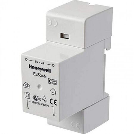
A chime swap sounds like a five-minute job until the new unit buzzes instead of ringing, or doesn't respond at all — and the old transformer sitting near the switchboard turns out to be the reason why. Getting the voltage and VA rating right is what actually decides whether the job holds up, not just reusing whatever transformer happens to already be in the wall. Here's how to size it correctly, where it usually ends up mounted, and the wiring basics that trip people up on this job.
Every chime has a rated voltage range and a minimum VA draw printed on the unit or in its spec sheet — usually somewhere in the 8-24V AC range, with VA typically between 5 and 40 depending on how many tones and how loud the chime is. The transformer needs to sit at or above that VA figure, and match the voltage range, or the chime will either stay silent, buzz weakly, or trip intermittently under load. A common mistake is treating "any low-voltage transformer" as interchangeable — a transformer rated for 5VA won't reliably drive a two-tone chime that pulls 10VA, even though the voltage matches on paper.
Where the existing chime is being swapped for a louder or multi-tone unit, check the new chime's VA draw against the transformer that's already installed before assuming it'll carry over. A DIN rail-mounted 8V 2A transformer gives enough headroom for most standard two-note chimes without needing to upsize the enclosure.
| Chime Type | Typical Voltage | Typical VA Draw |
|---|---|---|
| Single-note buzzer | 8-12V AC | 5-8VA |
| Two-note mechanical chime | 8-12V AC | 8-15VA |
| Electronic bell plate | 12-48V AC | 10-20VA |
These are typical ranges, not universal — always check the figure printed on the specific chime unit before locking in a transformer, especially on multi-tone or wireless-compatible units that draw more than a basic mechanical chime.
Three spots come up again and again on residential jobs: inside a junction box near the switchboard, tucked into the garage where the meter box sits, or mounted directly to the switchboard enclosure itself. All three work fine as long as the transformer stays accessible for future testing — burying it behind gyprock or inside a wall cavity with no access panel just means the next person who has to chase a dead chime is pulling apart plasterboard to find it.
Bell wire runs at low current, so a thin two-core cable is typically fine for most runs — but voltage drop becomes a real issue on longer runs, particularly if the transformer is at one end of the house and the chime is at the other. As a general rule, longer runs benefit from a slightly heavier gauge to keep the voltage at the chime within its rated range, rather than assuming any bell wire on the truck will do.
Most chime units have terminals labelled with numbers or letters on the back — commonly a front door terminal, a rear door terminal, and a common/transformer terminal. Getting these swapped is a common reason a chime "does nothing" even though the transformer is tested and working: the wiring is live, it's just landed on the wrong terminal for the button being pressed. Checking the terminal labelling against the wiring diagram printed inside the chime cover before terminating is worth the extra two minutes.
Assuming the old transformer will carry the new chime. A transformer that ran a basic single-tone buzzer fine for years often can't supply enough VA for a louder or multi-tone replacement — check the new unit's rating before reusing the old transformer.
Matching voltage but ignoring VA. An 8V transformer and an 8V chime look like a match on paper, but if the transformer's VA is below what the chime draws, it'll still underperform — buzzing, flickering, or failing to ring at all.
Mounting it somewhere inaccessible. A transformer buried in a wall cavity or behind fixed cabinetry turns a five-minute fault-find into a demolition job for whoever troubleshoots it next.
Ignoring voltage drop on long runs. A transformer that tests fine at the terminals can still leave the chime underpowered if the cable run is long and the gauge is too light for the distance.
Treating the primary side as low-voltage work. The bell circuit itself might be ELV, but the 240V side of the transformer isn't — that connection still needs to go through a licensed electrician.
Do I need an electrician to replace a doorbell transformer?
The low-voltage bell wiring itself typically doesn't require a licence, but the transformer's connection to 240V mains does — that side of the job needs a licensed electrician under AS/NZS 3000, even on a straightforward transformer swap.
Can I extend the run if the transformer and chime are far apart?
Yes, but check the voltage drop over the extended distance rather than just adding more cable. If the run is genuinely long, a wired doorbell extender can help maintain signal strength rather than relying on cable gauge alone.
How do I test if my doorbell transformer is dead?
A multimeter across the secondary terminals with the chime disconnected will show whether the transformer is putting out its rated voltage. No reading, or a reading well below the rated figure, usually points to a failed transformer rather than a wiring fault further along the circuit.
What VA rating do I need for a mechanical door chime?
Most two-note mechanical chimes draw somewhere in the 8-15VA range, though it's worth checking the specific unit — an 8-12V electromechanical chime will typically list its exact draw on the spec label.
Can I use a 12V transformer with an 8V rated chime?
In practice this can shorten the life of the chime's coil or make it noticeably louder and harsher than intended, since it's running above its rated voltage. It's generally best to stay within the chime's stated voltage range rather than overdriving it.
Is there an alternative if the wiring keeps failing?
If the existing wiring run is unreliable and re-running cable isn't practical, a dual power door chime kit can run off the existing transformer or fall back to battery power if that circuit keeps dropping out.
Getting the transformer right up front means less time going back to a job that should have been finished the first visit — worth checking Related Reading below for another power-matching job that comes up on similar sites.
Related Reading
Trade pricing on transformers, chimes and accessories, dispatched same day from Kingsgrove NSW.
Stock up on doorbell transformers at Schnap — everything you need in one place, dispatched same day from Kingsgrove.

SCHNAP Electrical Wholesaler - clear, upfront pricing that professional electricians trust

Get what you need in seconds. SCHNAP electrical wholesaler makes ordering quick and simple

Fast delivery anywhere - that's guaranteed. SCHNAP electrical wholesalers ship nationwide with same-day dispatch

Track your order every step of the way. SCHNAP electrical wholesale keeps you updated from click to delivery

SCHNAP is Australia's premier electrical wholesaler and electrical supplies, marketing thousands of quality products from leading brands. Trusted for nearly two decades by licensed electricians, contractors, and engineers, our range covers everything from basic electrical components to complex industrial electrical equipment
Our key categories include: LED lighting, designer switches, commercial switchboards, circuit protection, security systems & CCTV, and smart home automation
All products are certified to Australian standards (AS/NZS), backed by our 30-day, no-questions-asked return policy. Our expert technical team helps you quickly source the right solution for any residential, commercial, or industrial project, with daily dispatch from our Sydney electrical warehouse delivering Australia-wide
SCHNAP offers the most comprehensive electrical product range, with full technical specifications, application details, installation requirements, compliance standards, and warranties — giving professionals total confidence in every purchase


